
|
|
Forum Index : Electronics : Another Inverter Build
| Author | Message | ||||
Revlac Guru Joined: 31/12/2016 Location: AustraliaPosts: 961 |
Bought some tip35c transistors from a seller on aliexpress checked them when they arrived, they must have sent me the continence of there rubbish bin,  they were used burnt and blown, took some haggling but got it sorted out in the end. they were used burnt and blown, took some haggling but got it sorted out in the end.How long are the legs on those 10 000uf caps? Just thought if they were long enough i might be able to use the copper backing off the busted, mosfets stick them on the cap legs as a mounting pad and bolt the caps underneath the power board. Cheers Aaron Cheers Aaron Off The Grid |
||||
| Revlac Guru Joined: 31/12/2016 Location: AustraliaPosts: 961 |
These capacitors where taken from an old power supply, They worked well in the other inverter despite the 63v rating. Haven't found much info on them apart from being long life cap's, there is some 75v and 80v caps somewhere in the shed, not screw types though. 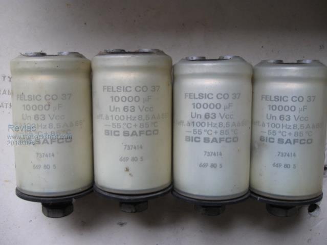 Looks like I will have to buy some 80v or 100v cheep ones eventually as they seem to be working okay for other's. Next job is to test the fets. Cheers Aaron Cheers Aaron Off The Grid |
||||
Madness Guru Joined: 08/10/2011 Location: AustraliaPosts: 2498 |
There was some banter on here somewhere about caps a while ago. From what I remember to test them is to put your battery voltage on them and see how much current the draw over after 24 hours or so. There are only 10 types of people in the world: those who understand binary, and those who don't. |
||||
renewableMark Guru Joined: 09/12/2017 Location: AustraliaPosts: 1678 |
The ones I got are around 7mm I got these ones They also sell groups of two so you can order enough for two boards here Cheers Caveman Mark Off grid eastern Melb |
||||
| Revlac Guru Joined: 31/12/2016 Location: AustraliaPosts: 961 |
Thanks for the link Mark  7mm, they don't give us much to play with. Cheers Aaron Cheers Aaron Off The Grid |
||||
| Revlac Guru Joined: 31/12/2016 Location: AustraliaPosts: 961 |
Connected all 4 caps to the batteries and the current is 0.63ma at 54v, looks ok. will see if its any different tonight. Cheers Aaron Cheers Aaron Off The Grid |
||||
| Revlac Guru Joined: 31/12/2016 Location: AustraliaPosts: 961 |
Checked the caps at lunchtime and the reading was 23ma WTF? Turns out that was because there was an inverter running the HWS at that time. All shut down in the afternoon and the reading was .03ma at the caps. Perhaps that's better. Anyway that will do me for a start. Cheers Aaron Cheers Aaron Off The Grid |
||||
| Revlac Guru Joined: 31/12/2016 Location: AustraliaPosts: 961 |
Tested 10 HY4008W fets when a had a chance. Tested with 12v and a variable resistor (set to 6.5amp) that I used for testing solar panels. Results: 3 at 20.6mV/6.5 = 3.1 milliohms Rds 7 at 20.8mV/6.5 = 3.2 milliohms Wound it up to 10A and the result was about the same? Expected lower reading than that, Something is a little off?. I suspect my ammeter is bad. However It still shows which ones are different. Cheers Aaron Off The Grid |
||||
| Madness Guru Joined: 08/10/2011 Location: AustraliaPosts: 2498 |
Aaron it is hard to get an accurate measurement, what is more important is consistency in the measurements you have taken. Taking measurements with really good contact as close as possible to the body of the MOSFET will give the best reading, the resistance of the legs is enough to give a an error. If all the MOSFETs read very close to the same value is what matters most. If any give a different reading then don't use them in the inverter. So far I have not had one HY4008 with a bad reading from the supplier I use. 3.1 to 3.2 is well and truly close enough so no problem with those you tested. There are only 10 types of people in the world: those who understand binary, and those who don't. |
||||
| Revlac Guru Joined: 31/12/2016 Location: AustraliaPosts: 961 |
Ok that confirms what I'm looking at, consistent reading's. The little ammeter was out a bit, now I understand the results that the amp drawn must be the same for each fet tested. Found a pluggable terminal block/screw terminal socket, and the fets legs just plug in nicely for testing. 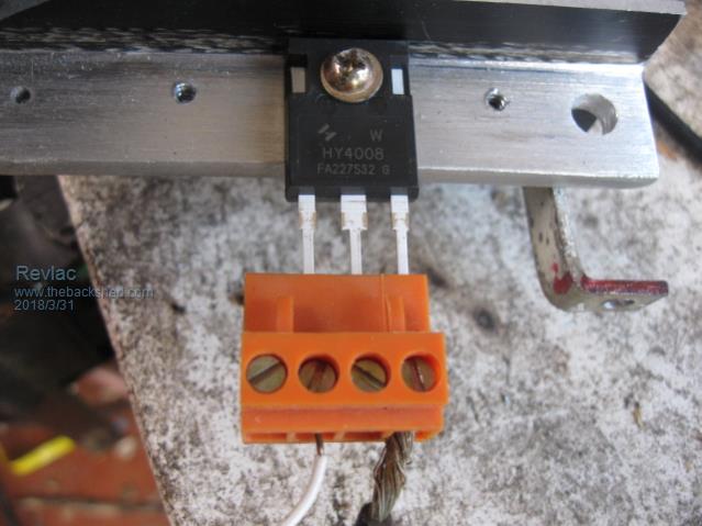 Just after taking this photo I started testing more fets but got a bit distracted by some of the wildlife. Come back 10 minuets later only to find I had left the power on the test rig and the resistor heated up next to the ammeter and melted the Arse out of it, little meter is now in the bin, Hindsight should use a momentary on switch. Nothing wrong with the fet that was connected, never even warmed up, good idea to test them on a decent heat sink. Working on some other things till I calm down a bit. Cheers Aaron Off The Grid |
||||
| Madness Guru Joined: 08/10/2011 Location: AustraliaPosts: 2498 |
I fix the terminal block and just hold the MOSFET in it with a bit of pressure. When you take it out no current flows, only takes a second to get a reading. There are only 10 types of people in the world: those who understand binary, and those who don't. |
||||
| Revlac Guru Joined: 31/12/2016 Location: AustraliaPosts: 961 |
OK a little more progress, decided to mount the heat sinks to a piece of fiberglass and then mount the control board on top, it was just easer to assemble, less pissfarting around than trying to do it the other way with this heat sink layout. This will leave room at either end to mount a fan and looks a little more neat.....IMO. Still need to make an IDC cable and test it again. 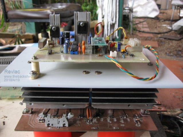 Had a bit of a look at this AN-1045b found it interesting and somewhat relevant, someone may find something useful in it or some other ideas, makes me wounder if we could play with the dead time a little bit depending on the design and layout being used, the default setting has been working for some, but may be a factor (Make it or Break it)..? Did a bit of a test to check the signal out put of the IR2110 at TP 5 the 50Hz square and its looking good. 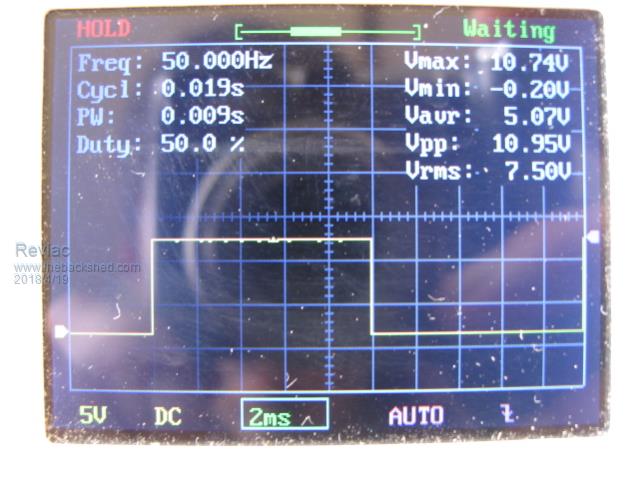 Adjusted the voltage on the OSC and its strait no spikes, will have to see if it stays that way when tested at the gates of the fets. 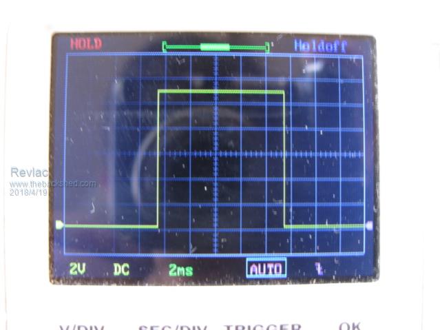 I also notice the drive voltage is too low, 13v zener is a bit off so will try 18v zener. A little quirk I didn't notice before, as I run this test without the power board connected it will run for a few seconds then stop blink 3 times then 4 blinks and cycles, nothing unusual about that, however when I turn it off during this off cycle it will just start the next cycle with a few pulses before it is really off, at first I noticed the led blink when it was supposed to be off, then checked it with the OSC and saw it in action. 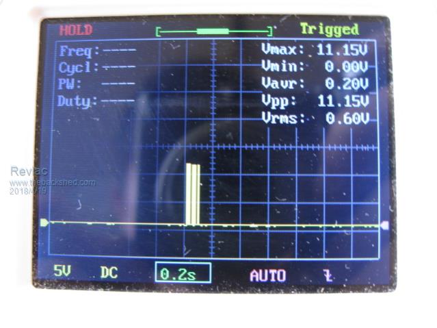 Don't know yet if that happens on any of the other outputs yet. Cheers Aaron Off The Grid |
||||
| Madness Guru Joined: 08/10/2011 Location: AustraliaPosts: 2498 |
Must be nice to be able to see what you are doing now Aaron with a CRO. I found increased dead helped when I had other issues but when everything was working right the shortest dead time setting of the 8010 gave the best result. There are only 10 types of people in the world: those who understand binary, and those who don't. |
||||
| noneyabussiness Guru Joined: 31/07/2017 Location: AustraliaPosts: 506 |
Aaron, ive noticed that to. The eg8010 will even start the next cycle before shutting down, doesn't seem to matter though. . I think it works !! |
||||
| Revlac Guru Joined: 31/12/2016 Location: AustraliaPosts: 961 |
Gary I would be poking around in the dark without one of these things, sometimes things just work when put together, until something happens and then......well you know the story.  @ noneyabussiness I checked all the SPWMOUT 1-4 and they all have a vary short output signal (Counted 5 Pulses on the 50Hz side), perhaps its just the first part of the soft start, but if that doesn't cause any trouble then it doesn't matter. Cheers Aaron Off The Grid |
||||
| johnmc Senior Member Joined: 21/01/2011 Location: AustraliaPosts: 282 |
Good Day Revlac What is the shape of the wave from pwm3 and pwm4 at the input of the IR2110 chip, as I am having trouble with hash at the gates of the fets. cheers john johnmc |
||||
| Revlac Guru Joined: 31/12/2016 Location: AustraliaPosts: 961 |
john I Will Try and check tomorrow if I have some time, everything is a bit damp ATM, after the storm and bloody lightning hit something not far away. Do you have a test signal you can run through your CRO to see if its clean? if you haven't already. Cheers Aaron Off The Grid |
||||
| Madness Guru Joined: 08/10/2011 Location: AustraliaPosts: 2498 |
John if you take out the IR2110's and check the output of the 8010 it should be perfect. You only get 3 seconds before it will shut down but that is long enough to see the output. Then can then work down the line from there. There are only 10 types of people in the world: those who understand binary, and those who don't. |
||||
| Revlac Guru Joined: 31/12/2016 Location: AustraliaPosts: 961 |
OK this test is (SPWMEN3)At the IR2110 input using the (RC Filter) 5.1K resistor and 0.1uf cap at the end of the probe as per the EGS002 data sheet. Without the RC Filter it will look a bit hairy. 3 seconds isn't much time for a snapshot but this is the best I could do, Be better too if this dopey held the camera still. Not sure if I'v done this properly but It seems OK to me. I think this is the soft start part of the cycle. 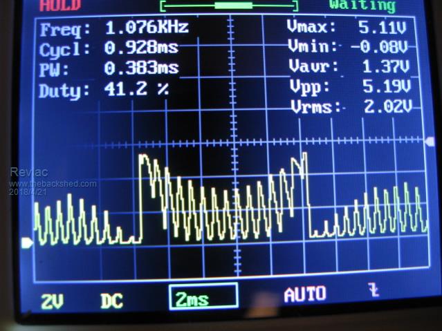 And this is a bit further along 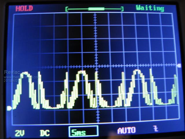 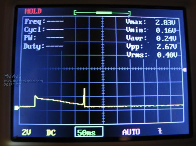 This is the reset button pressed and realest, It dose not appear on the on the IR2110 out put that i could see. Don't take too much notice of the number's in the picture. Cheers Aaron Off The Grid |
||||
| Revlac Guru Joined: 31/12/2016 Location: AustraliaPosts: 961 |
This in an old cable I had planed on using and crimping a new end on. 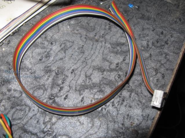 Unfortunately I seem to have pore choice of words.  I'm going back to my cave now. Cheers Aaron Off The Grid |
||||
