
|
|
Forum Index : Electronics : MPPT software suggestion in pseudocode
| Page 1 of 3 |
|||||
| Author | Message | ||||
| domwild Guru Joined: 16/12/2005 Location: AustraliaPosts: 873 |
Encouraged by Warpspeed's suggestion, although more biased towards a hardware solution I would like to suggest a code solution to the problem of getting a Picaxe to vary the pulsewidth according to the observed Amps read: set oldamps to 0 read newamps if newamps > oldamps Taxation as a means of achieving prosperity is like a man standing inside a bucket trying to lift himself up. Winston Churchill |
||||
| domwild Guru Joined: 16/12/2005 Location: AustraliaPosts: 873 |
Sorry, hit the wrong button. Let's try again: set oldamps to 0 read newamps if newamps > oldamps then increase pulse width of PWM if newamps < oldamps then decrease pulse width of PWM set oldamps to newamps Very rough pseudocode, but what do you think? Taxation as a means of achieving prosperity is like a man standing inside a bucket trying to lift himself up. Winston Churchill |
||||
Gill Senior Member Joined: 11/11/2006 Location: AustraliaPosts: 669 |
G'day Dom, As you say, "a rough pseudocode" but still what you are pointing to is right as I see it. I would make the point that the prop would need to be fashioned for max power at max revs at 100% duty cycle as this code can only reduce loading not boost it. Though an improvement, as I understand it, this is not MPPT. What you are doing is reducing generator loading on the prop and so track the wind power curve as opposed to the wind velocity as our methods do now. I understand that MPPT achieves this also as it adjusts the volts and amps ratio to produce the highest watts into the battery. Your PWM switching approach does not modify the volts and amps ratio just their level. You haven't made Chief Engineer but a valuable worthwhile suggestion never-the-less. 
Would you like to make a windmill to employ this technique? was working fine... til the smoke got out. Cheers Gill _Cairns, FNQ |
||||
| GWatPE Senior Member Joined: 01/09/2006 Location: AustraliaPosts: 2127 |
Hi Gill, The PWM in conjunction with an inductor and freewheeling diode will give the volts to amps conversion and allow the rotor to follow the wind speed. The power output could follow the wind energy. Gordon. become more energy aware |
||||
| Gill Senior Member Joined: 11/11/2006 Location: AustraliaPosts: 669 |
Dom, Here's the code that you have indicated. It is quite small so should tick over very fast. I set the lowest duty to 100 as you don't want it to not be charging else it will never have 'newamps' or any amps for that matter. #REM Dom's Wind Power Tracker Version 1.0 21st June 2008 #ENDREM #picaxe 08m symbol duty = w0 symbol oldamps = w1 symbol newamps = w2 Setup: oldamps = 0 duty = 500 Run: readadc10 1, newamps ; read in amps if newamps > oldamps and duty < 1000 then inc duty ; up duty if more else if duty > 100 then dec duty: endif ; down duty if less pwmout 2, 249, duty ; adjust pulse width oldamps = newamps ; reset goto Run END Page formatting lost when copied here, so here's it zipped up 2008-06-22_021012_Dom's_code.zip Piece of cake. Now all you have to do is make it. was working fine... til the smoke got out. Cheers Gill _Cairns, FNQ |
||||
| domwild Guru Joined: 16/12/2005 Location: AustraliaPosts: 873 |
Thanks, Gill and Gordon. Gill: I believe it was Warpspeed who said the batteries would keep the voltage fairly steady, so I did not do a power calculation. More later. Taxation as a means of achieving prosperity is like a man standing inside a bucket trying to lift himself up. Winston Churchill |
||||
| domwild Guru Joined: 16/12/2005 Location: AustraliaPosts: 873 |
Gill, I do not understand the comment of the code not loading the prop. It will load or unload the prop to match the wind. Of course, the initial values have to be correct for the hunting up/down to commence. Oldamps is in the initialisation section and does not show up in the "mppt" subroutine. If voltage is not fairly constant, then we can simply word the code as follows: initialise pulse width, oldpower to some value sub starts here read volts read amps watts = volts times amps if watts > oldpower load the prop more then increase pulse width if watts < oldpower unload the prop then decrease pulse width oldpower = watts do nothing if power is the same .... To use wind speed to drive PWM may be a problem as it is varying too quickly and may need some tricky averaging; the inertia of the mechanical parts will not allow a direct relationship (in time) between wind speed and watts produced. Might be tricky to work out the delay required between measured wind speed and later resulting watts. It is not my intention to become an engineer on this forum; I am quiet happy in my position as president of the West Australian Flat Earth society. Fieldlines has a schematic of a PWM-driven totem pole of MOSFETs used to drive the diversion load. So for a person without a black belt in electrickery like myself it appears most of the MPPT PWM building blocks even on the hardware side appear to exist. I am slowly building the mill and electronics and am standing on the shoulders of giants, like Glenn, who have done all the volt, amp, wind speed, RPM and diversion switching software written already with Piclog. So if we all pool our ignorance, the MPPT job should be easy. Perhaps it may only ever remain as an intellectual exercise. Taxation as a means of achieving prosperity is like a man standing inside a bucket trying to lift himself up. Winston Churchill |
||||
| GWatPE Senior Member Joined: 01/09/2006 Location: AustraliaPosts: 2127 |
Hi Dom, A totem pole expression as used in electronics refers to the series arrangement of 2 transistors. The Mosfets referred to in the fieldlines thread are just a parallel arrangement. The mosfet driver uses a totem pole arrangement. I have used complementary Mosfets in a totem pole arrangement in a Digital Audio amplifyer, switching between a 50V rail at 300kHz. On the topic of a MPPT. Hi Gill, I have built many designs with similar code to the above. I was not able to get a stable design in a boost or buck arrangement. These were the type of feedback control systems I was testing when the MPPT thread was closed last year. I gave up on this approach. I have tested the code above in my test rig. I use an alegro hall effect sensor, so I had to mod the code a bit. It did not work either. After the MPPT thread closure I have continued my R&D. I have developed a different code arrangement that mimics the analogue cct I currently use. I have found that the "direct" control of pulsewidth is a more stable control system and can load a windmill pretty close to the wind power curve, within the limits of the generator/blades etc. I have had a digital version on test and the boost arrangement provides similar performance to my analogue design. I have yet to test a buck arrangement. I have to say that with the procedure for trying to maximize the output using a peak maximizing algorithm, the performance is significantly affected. The windmill is underloaded as the wind power increases and is overloaded as the wind power decreases. This creates a cyclic loading pattern that oscillates above and below the optimum power level. Dampening, compounds this problem. This problem was demonstrated experimentally on my windmill and on a power supply that I use that simulates a windmill output. I think that most will agree that this is what should happen. If the windmill rotor is able to respond linearly to windspeed, then the output loaded voltage should also follow a linear relationship. There will be a slight plateauing due to the winding resistance. For a doubling of the windspeed, the power should increase a factor of 8. The voltage should be double. The current should therefore be a factor of 4 increase. For an ideal windmill producing say 250W into a battery at 25V at 300RPM, this is 10A. if the windspeed was halved, then the power output would be expected to be 31W and 150RPM and 12.5V and 2.5A. I would say that most DIY windmills are severely over driven. A 3m dia rotor should give approx 1kW of shaft energy to a generator in 10m/s windspeed. My windmill with 2m rotor dia with approx half this capture area does produce around 450W at 10m/s windspeed. A Maximizer does enable my windmill to extract as much power as possible from the wind energy. I am setting up a F&P windmill with 3m rotor dia. I know that this will never produce 1000W. My objective is to use a large rotor to increase the low wind output. The boost maximizer will allow power extraction from a generated voltage of 8VDC. I am expecting a doubling of annual average power output, for the wind conditions I experience. I see a maximiser matching the rotor to the generator within the limits of the combination. A maximizer can allow power to be generated at low windspeed from a windmill that has a high speed cutin. A maximizer can also allow a windmill that has a very low cutin, to effectively unload the mill and allow better matching of the rotor to the generator, so more power is extracted. Every DIY design will have specific battery voltage and blade generator characteristics that will not change much once a design is selected. I see a boost or buck design maximizer that can better match the components. I do not see a single magic bullet type universal MPPT. A windmill essentially follows a set response to the windspeed, that is marginally changed by the SOC of the battery, or the impedance of a differeent sort of load. I had been put off discussing this subject. Even though I have not had any success with the above MPPT sort of control system, others may have more success. The PIC programmers may nail it. I hope to include my "direct" control cct as part of a submission to Gizmo on my setup, that will include photos. My boost design has mill shutdown control, battery voltage limiting and the maximizing function using a picaxe 08M. The code should also allow for a serial LCD to display power and status. Gordon. become more energy aware |
||||
| Gill Senior Member Joined: 11/11/2006 Location: AustraliaPosts: 669 |
Dom, Addressing your first point; I don't see where I have said or said anything that could be misunderstood to be that the prop won't be loaded. That is the purpose of the code after all. The only thing that may be difficult to understand was my advising the lowest duty cycle is set at 100. If that's it, I'll explain. When the wind stops newamps is lower than oldamps so the duty cycle is reduced (normally) to 0. When the wind starts again there can be no newamps more than 0 to increase the duty cycle because at 0 duty cycle no current can flow. So I set the lowest duty as 100. I think I should have made it 500. (duty of 1000 = 100% ON, 500 = 50% ON,and 100 = 10% ON). Second point; oldamps is very much in the Run routine. Stop flat earthing and put your glasses on. That is a fully working code of what you suggested initially, and I agree it is worth a try. However IT IS NOT MPPT. It does not change the ratio of volts and amps say like a transformer, buck converter or Star/Delta switching. It merely reduces the loading on the prop where appropriate by turning the power OFF and ON for a microsecond as set by PWM. This is performing the same correction of power mismatch as a variable pitch prop would. Because you have not indicated any of the fancy MPPT circuitry Gordon refers to, there is no need to worry about voltage in the code. Yes the components are there, the building block for warps switching is there even the code is there for that, but the building blocks for MPPT are not there. I disagree that with enough people sitting in the back seat of knowledge that you can drive the taxi. Isn't the most you can do, is to tell a driver where you would like to go? was working fine... til the smoke got out. Cheers Gill _Cairns, FNQ |
||||
| Gill Senior Member Joined: 11/11/2006 Location: AustraliaPosts: 669 |
Gordon, As I understand what Dom has reintroduced is for the purpose of pulsing say Nch Mostets in the negative supply to the battery and that is all. He is calling this MPPT but, like me has little understanding of buck conversion or freewheeling diodes that you speak of. Sorry I can't chew the fat as it were over most areas of what you have played with. It is beyond my knowledge. I only heard of maximisers a few weeks ago. A couple of new acquaintances have been using them on their hydros for years now and swear by them. Now that you mention them I'll have to Google them along with freewheeling diodes. They said the price is easily over $1000 so I won't be getting one in the near future at least. The functions they described sounded an awful lot like MPPT to me. Is there a difference? If so what do you understand that to be? was working fine... til the smoke got out. Cheers Gill _Cairns, FNQ |
||||
oztules Guru Joined: 26/07/2007 Location: AustraliaPosts: 1686 |
Gill, "However IT IS NOT MPPT. It does not change the ratio of volts and amps say like a transformer, buck converter or Star/Delta switching. It merely reduces the loading on the prop where appropriate by turning the power OFF and ON for a microsecond as set by PWM. This is performing the same correction of power mismatch as a variable pitch prop would. Because you have not indicated any of the fancy MPPT circuitry Gordon refers to, there is no need to worry about voltage in the code. " I am not sure this line of reasoning is actually correct. If we use your analogy of the variable pitch prop, then we have to say that this process is an impedance matching activity.In effect we sacrifice TSR for torque as we make the pitch coarse, for the same power, but at different revs to match the alternator. This is mppt. It is the same as if we use a transformer to achieve the some coarse impedance match, but unlike variable pitch it is a one off impedance match, and so does not match the dynamic blade any where near as well as variable pitch. (We may get something from the better energy transfers as the frequency increases with TSR and EMF I guess as well) If we had variable transformer, then we could have mppt via transformer. The buck converter is the same as the transformer, until we hook it up to a dynamic driver, then we effectively have the variable transformer, and so mppt again. Any time we make changes to the impedance match of the dynamic driver to the static load, we are attempting to emulate mppt. Dom's case in question, is no different. If by time switching, we store energy in the inertia of the prop, to be harvested next pulse,or allowing it to get some giddy up going, then we are in effect transforming the energy available in the blade via "time shift" or balancing inertia.... effectively becoming a clutch/gearbox by storing up kinetic energy for later use and/or by allowing the TSR to improve so there is more to harvest when we do. But we get more than that, as we try and get out of stall, we have more power to play with, and we get to access it because we pulse switch to get the tsr up. This by definition will increase the EMF in the alternator, and so when we switch, we will have more power in the result because we are switching a higher (EMF-cutin volts)squared/ alternator resistance (air core type) to get an increase in power out. (W=(VxV)/R..... V=EMF-cutin volts) or "forcing volts" The output volts stay the same, but the resultant current and power may even increase ....even if the time of the pulse is smaller..... smaller piece of a bigger pie so to speak. It gets tricky at stall, because you may reduce the pulse, only to find the power increases. (like using a line resistor, we can increase the available power by increasing the TSR...... we do this using an energy wasting technique to get more energy out?????). This happens because as we relieve the load from the prop, it uses this extra energy to increase tip speed, and so has got more lift available to it....etc. etc. In Doms idea, we will then increase pulse width, but this may strangle clearing stall, and so we may get hunting in this region, as what happens from our pulse increase/decrease, may not make sense to this simple strategy. When out of stall, it may make more sense. So at first glance, it seems to be a power limiting strategy, but because of the dynamics of the TSR and EMF and the foibles of blade behaviour,cubic function of the wind, squared function of the alt, it should lead to more power available to the batteries, which I guess by definition, will be an attempt at maximising the power out from the wind in. My hats off to Gordon who has achieved success via analogue means. I think that route is the most promising. My hunch is that the digital will require much more computing and clean inputs than will be found readily. It will also require far more thought to take care of the stall part of the equation,and a lot of other things I haven't thought of, which analogue seems to cope with. Well thats my take on it, this is the fancy mppt circuitry, it just manipulates the energy quotient slightly differently than Gordons, Doms uses the kinetics and alternator and blade/wind characteristics rather than buck/boost, but the program should work the same(ish)for both topologies, if it was to work at all..... but I've been powerful wrong before. .........oztules Village idiot...or... just another hack out of his depth |
||||
| GWatPE Senior Member Joined: 01/09/2006 Location: AustraliaPosts: 2127 |
Hi Gill and Oztules, I had no idea that dom was only intending chopping the DC from the windmill. I see that a MPPT is a program that continuously adjusts the pulsewidth. An inductor and associated componentry convert one VI to a different VI based on the ratio of on/off time. The microprocessor makes measurements and decides if the power level has increased or decreased from the last time a measurement was made. The micro ultimately attempts to track the maximum power point. The word maximizer has been used for MPPTing. I have used maximizer to distinguished a difference in operation to a MPPT. The concept I am adopting is where the electronics already knows the correct loading to apply. The TSR of the windmill may vary a little through the loading curve. My code is adapted to a function, either boost, or buck operation. The code is adapted to the ratio of windmill voltage to battery voltage. A set program, "direct" control is used to change the pulsewidth according to the loading needed. As long as the windmill can produce slightly more power than the loading setting, then the maximum power is obtained. At the end of the day the alternator has a broad VI band and this coupled with the VI conversion in the boost or buck cct is probably why a MPPT has such a difficult task. The "direct" control suffers no oscillatory tendency. I posted a pic of a pcb last year on the MPPT thread. This pcb is what I have adapted for my latest design. This is only a boost type design at present. A Windmill is not a devious machine. The power output is dependent on matching the load to the available energy extracted from the wind. The energy extracted is related to the wind energy at the blade optimum TSR. The wind energy is known in relation to windspeed and it is a cubic relationship. I have essentially broken the graph up into many small sections and allocated a pulsewidth to each section. The increment component is the current, that selects the appropriate pulsewidth. An adjustment is made to the pulsewidth proportional to the load voltage. This allows the transformer action of the inductor to better track the windmill generated voltage to load voltage ratio. I am using a formulae to calculate the increment steps at present. As long as the windmill is never overloaded, a better than 90% matching can be obtained. The limiting factor is the integer maths and PWM output increments available. This is why the analogue solution still gives a slightly better loading, but the digital solution is far simpler to set up. If the windmill is overloaded, then the same situation occurs like if the stator is mismatched. The blades will require more wind to increase shaft power. I intend making another test board. At present my only testing is on the power supply, as there is little wind. I am expecting gale force wind on Wednesday. Some windmill testing can come after that. Gordon. become more energy aware |
||||
| Gizmo Admin Group Joined: 05/06/2004 Location: AustraliaPosts: 5181 |
MPPT discussions make me nervous 
To display code better on the forum, you can use the {CODE}Blah Blah{/CODE} tags, replace the { and } with [ and ] eg for i=1 to 100 Print i next It should, in theory, keep the formatting Glenn The best time to plant a tree was twenty years ago, the second best time is right now. JAQ |
||||
| domwild Guru Joined: 16/12/2005 Location: AustraliaPosts: 873 |
Friends, I stand corrected! By the way, I have used pseudocode to indicate to non-Picaxe forum members just the logic. As the forum has indicated the load-varying approach I have seen before is not is not a good idea, then I am certainly not going to build it and waste my time. Perhaps a Picaxe pulse-width controlled buck converter is the answer, but there seems to be further problems with battery charging; like Pandora's box! Anyway, it appears my 10 cents worth is not reducing the complexity of this issue and the thread may once again just become a dream. Taxation as a means of achieving prosperity is like a man standing inside a bucket trying to lift himself up. Winston Churchill |
||||
| oztules Guru Joined: 26/07/2007 Location: AustraliaPosts: 1686 |
Dom, I have built plenty of things that were almost a complete waste of time. I have blown up more than my fair share of fets and other innocent components as well, but very rarely is it wasted time. Even though whatever it is may not work, it may give you better insight to what may work next time. The fact that Gordon didn't hit paydirt first time out should give you some comfort that true MPPT is not easy. I haven't even seen a commercial unit being anything other than better than nothing. In truth, load matching can be as simple as standing next to the batteries and disconnecting them and reconnecting them disconnecting etc.etc.to keep the blades out of stall. Next stop is probably load resistor which can yield very good results,(the difference between not working and a satisfactory system) but with heat loss. Next up is probably the scheme you described (if you can get the pic to make the right decisions) which I see as similar to the resistor, but without much heat lost to the system. Next we use the bones of the last to drive a buck or boost or pushpull, hbridge, half bridge, forward converter, two switch forward etc etc. chose your poison here. The converter is the simple (comparatively) part of the show, it is telling it what to do that seems to be the sticking point. If by building a simple chopper helps you get the pic to work sensibly with whatever data you supply it with, you will have beaten most of us. It would then be a simple step of controlling a converter of choice, and you will have won. So even if you never get the perfect converter, you will be further along the way to achieving it. I have no qualms whatever in building the converter, but haven't currently settled on a path to start providing it with sensible pwm signals to work. Thats the tough part. If I was a pic fan, I would implore you to test Gills code on your switcher, and maybe get more real world information on what does/ does not work, but I prefer analogue, so the code is not important to me... But for you pic people, it could prove to be useful experiment. The main thing though is to have some fun, and a few failures seems to help..... but maybe thats just me. .........oztules Village idiot...or... just another hack out of his depth |
||||
| Gill Senior Member Joined: 11/11/2006 Location: AustraliaPosts: 669 |
G'day oztules, Wow that's a lot of technical reasoning you present there. Unfortunately I disagree with you right at the first statement. It is not impedance matching, and for want of definition I'll call it MPPTw as opposed to MPPTg. The w stands for wind power and the g stands for generator power. As I have tried to explain the two are independent. Surely we are aware the term MPPT is already an established term and is the MPPTg I defined above no matter what the generator type ie. wing gen, PV array etc. We can't use the established term for both. If I had a 2" wind pump and changed it for a 21/2" and it stalled the blades, I could a. vary the blade angle b. reduce the load by changing to say 21/4" or back to 2" Nothing to do with impedance matching with not an electrical component in sight. It is reducing the power generator draws and that can be achieved by shutting off the power as in PWM, or winding out the rotor. Though inserting inductors in the AC side will increase resistance and reduce gen load on prop, the inductor is still not for matching of impedances in this case. For the accepted MPPT description I refer to 2008-06-24_124445_MPPT_Technology_.zip. Here I see a maximising of the amps into the battery from the SAME GENERATED POWER(same prop load). As I have said before, it is by the manipulation of the amps to volts ratio for the SAME POWER that gives us the MPP. It relates to generator to battery current increase for the same gen power. Because the gen power is the same it cannot affect the wind to gen power transfer as maximised under MPPTw. If we don't have a consensus, an understanding of what each of us is talking about, there can be little hope much development. Still it is the slashing, thrusting and parrying of these discussions that hones our own understanding. I can see Glenn trembling with each post, poor old fella dare not express a view. was working fine... til the smoke got out. Cheers Gill _Cairns, FNQ |
||||
| Gill Senior Member Joined: 11/11/2006 Location: AustraliaPosts: 669 |
Gordon, Thanks for the comments on the maximiser. I have found a reference to the Maximiser referred to by my mates. It is indeed a MPPT. Though it's purpose appears to be solar, both the blokes I met have been using them for years on their Baldor DC motor Hydros. Here's a copy of the site(I've lost the address) 2008-06-24_132413_AERL_Maximizer.zip What is of interest is the high voltage this one can work with. I thought most solar MPPT were made for around the 20v mark and this made them unsuited to the broader voltage range of wind generation. In your MPPT designs are you trying to match the gen with the wind as well as maximising the current into the battery with the one unit? Also checked out 'freewheeling diodes'. Harrr! knew about them already, just not by that term. was working fine... til the smoke got out. Cheers Gill _Cairns, FNQ |
||||
| Gill Senior Member Joined: 11/11/2006 Location: AustraliaPosts: 669 |
Glenn, Thanks for the code posting instruction. That'll make it much easier to read in future. was working fine... til the smoke got out. Cheers Gill _Cairns, FNQ |
||||
| GWatPE Senior Member Joined: 01/09/2006 Location: AustraliaPosts: 2127 |
Hi Gill, This is the purpose of my Maximizer. As long as my windmill is spinning and the wind power is measurable, my cct extracts power proportional to the wind energy. There are plenty of MPPT for solar. The AERL units work well when tuned, with hydro systems as well. In a wind system, the units work as a way of better matching a generator to a battery load. I do not believe there is a maximizing function to wind energy as such. I had spoken to Stuart, from AERL, re modifying my AERL Solar/hydro MPPT for wind. He did not recommend it. I have the picaxe "direct" control unit on test at the moment. I have had to include some code modifiers to compensate for the battery voltage. I was losing about 10W at the bottom of the power band when the battery voltage was low. The windmill cutin voltage was 11V instead of 9V. This is now sorted. The windmill now sounds almost the same and loads similarly to my original analogue design. Here is a photo of my 8-28V, 15A boost maximizer, top side, PCB. The bottom side is published on the original MPPT thread. 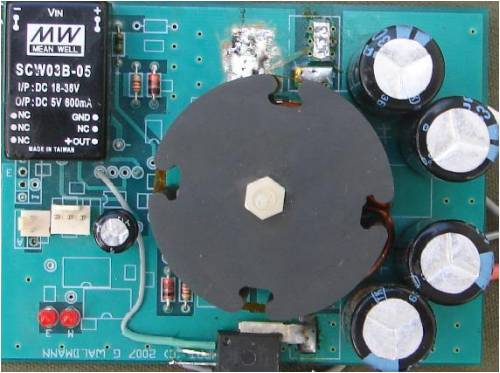
The double sided PTH PCB has the input and output filter caps,[each 2x3300uF/35V], the SMD Mosfet switching device,[160A/60V], the SMD shottky diodes,[2x20A/60V], potcore inductor, 5V & 12V power supplies, Alegro Hall effect current sensor, SMD picaxe 08M, buffer and SMD mosfet driver, voltage sensing divider, indicator, etc. I have had to spend a fair bit of time reprogramming in situ, trying the various mods as the mill was flying. It is highly probable that my code will perform badly without mods on another windmill. I will test on my F&P mill before I am prepared to release it. This code on my windmill does load close to a cubic power curve, until furling starts. I am planning to run my F&P mill as a boost arrangement as well. If the mods for my F&P are minimal, the unit will probably work the same on any windmill that had a high cutin speed. .. .. Gordon. become more energy aware |
||||
| Gill Senior Member Joined: 11/11/2006 Location: AustraliaPosts: 669 |
Good, sounds like plenty to keep you busy. was working fine... til the smoke got out. Cheers Gill _Cairns, FNQ |
||||
| Page 1 of 3 |
|||||
| The Back Shed's forum code is written, and hosted, in Australia. | © JAQ Software 2026 |
