| |
Page 1 of 6   |
| Author |
Message |
BenandAmber
Guru

Joined: 16/02/2019
Location: United StatesPosts: 961 |
| Posted: 05:23pm 21 Feb 2019 |
 Copy link to clipboard Copy link to clipboard |
 Print this post |
|
Time to figure out what parts I need to upgrade it to make it Bulletproof
So i get practice before I get my big board
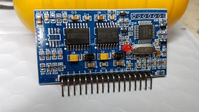
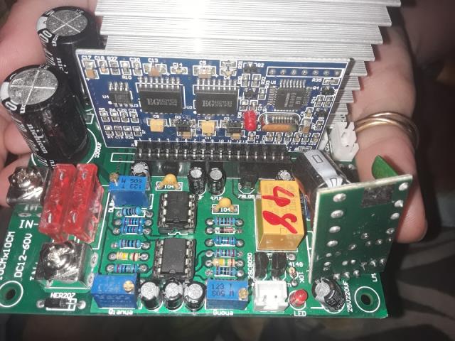
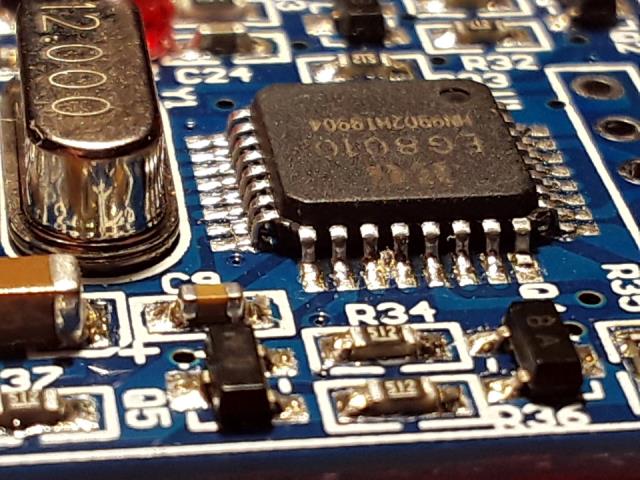
This little board has a EGS002
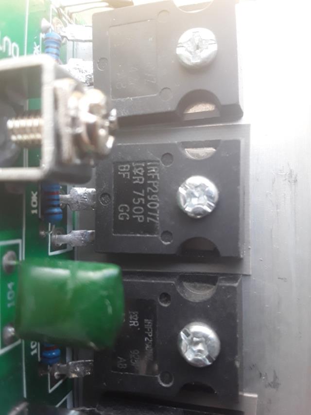
it also has four iRFp 2907 Z mosfets
it is supposed to B good up to 1800 watts it has two little 470uf 100 volt capacitors
2 soldered in car type fuses 40 amps each 4 trim pots
2 LM 358 chips
it came with a separate dark red or maroon hard plastic filter capacitor
the number on it is MPP 335 k 2 f. Co223212f
I have a extra ESG 0 0 2 and the little LCd screen also
be warned i am good parrot but Dumber than a box of rocks |
| |
BenandAmber
Guru
Joined: 16/02/2019
Location: United StatesPosts: 961 |
| Posted: 05:35pm 21 Feb 2019 |
Copy link to clipboard |
Print this post |
|
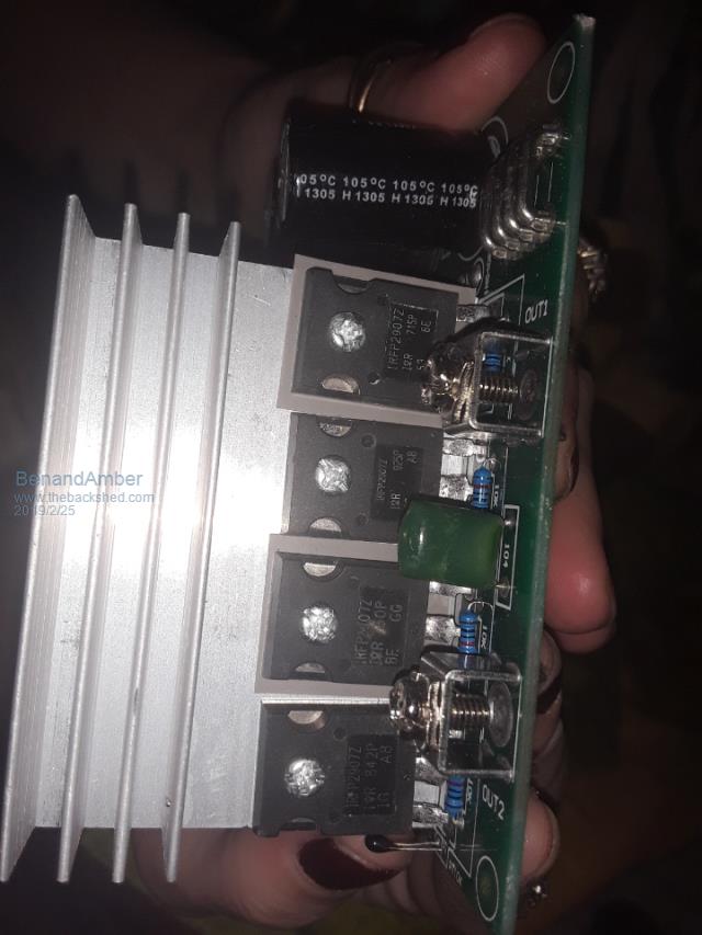
All 4 irfp2907z the print on each one of them looks a little bit different
like they're not from the same batch
the top line of print is all the same letters and numbers
the second two lines of print are different letters and numbers
it came with one of the capacitors bent over
and the little board that sticks up vertically also bent over
which I think controls what voltage input came packed in Thin star foam looking stuff wrapped around it
With a little bit of tape no box not much protection at all
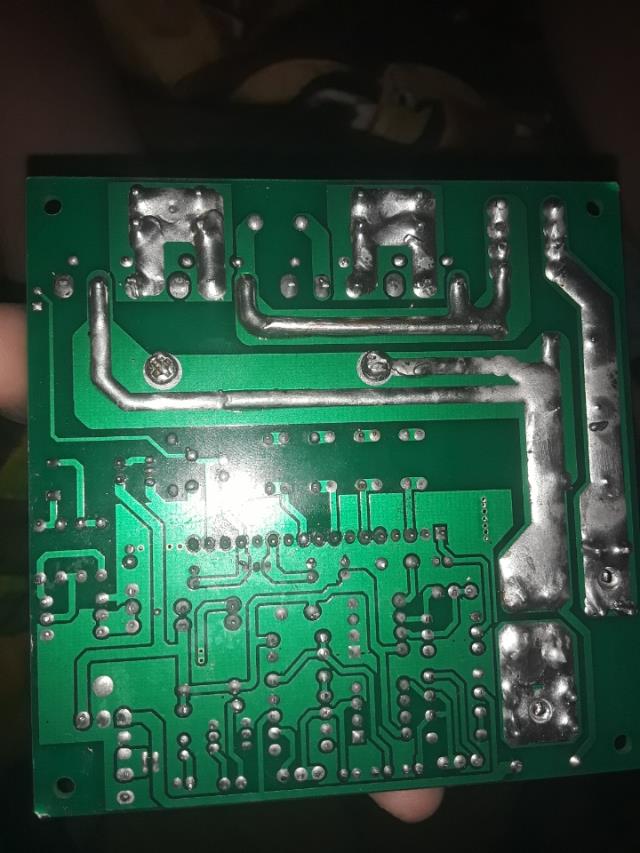
it has three bad solder points on the bottom
to dry joints and one without any solder all components go through the board and solder on the bottom
the mosfets are incredibly close together and it has screw on connectors for the in from battery and out to Transformer
the board is 4 in by 4 in
the heatsink is the tallest thing sticking up and it is 2 and 1/8 inches tall
I paid $28 with shipping off of eBay
I guess you get what you pay for LOL
the only thing that was a surprised to me was I thought the mosfets was going to be hy4008
looking forward to any comments or suggestions this is my practice boardEdited by BenandAmber 2019-02-23
be warned i am good parrot but Dumber than a box of rocks |
| |
BenandAmber
Guru
Joined: 16/02/2019
Location: United StatesPosts: 961 |
| Posted: 06:48am 22 Feb 2019 |
Copy link to clipboard |
Print this post |
|
https://www.ebay.com/itm/Pure-Sine-Wave-Power-Frequency-Inverter-Board-12-24-48V-600-1000-1800W/362490571177?hash=item54 661f29a9:m:mhPyFyazEiGJzOlfxDsHrAg. This is the board I have I hope this link Works because I can't figure out how to upload pictures
be warned i am good parrot but Dumber than a box of rocks |
| |
BenandAmber
Guru
Joined: 16/02/2019
Location: United StatesPosts: 961 |
| Posted: 09:03pm 24 Feb 2019 |
Copy link to clipboard |
Print this post |
|
I got to looking real close at this little board trying to figure out how it works
I had my magnifying glass out there
I'm getting a little bit old
I noticed the little 8010 cip had two pins shorted out to each other
I have pictures. I just don't know how to put them up here
help please but anyway I had another EG s002 board so I switched them them
but this was a good excuse to tell the wife why I needed a rework solder station yeah Boy I got it ordered
I have three irons already
the giant one was probably made in the 30s I love it by the way it's just Giant
I have one of those Walmart $10 jobbies then I have one I ordered off of eBay that I was very impressed with
cost of like 7 or 8 bucks blue and it's got a temperature setting on the handle of it ceramic element inside really impressed with that oneEdited by BenandAmber 2019-02-26
be warned i am good parrot but Dumber than a box of rocks |
| |
Warpspeed
Guru
Joined: 09/08/2007
Location: AustraliaPosts: 4406 |
| Posted: 09:24pm 24 Feb 2019 |
Copy link to clipboard |
Print this post |
|
To post pictures, first hit the reply button as you already do.
There are twelve little squares at the top. The eleventh square (with the tree and the up arrow) allows you to search through your own computer and select the image you wish to post.
A small new window will open telling you what type of image files can be posted and the maximum size allowed. Give that a go..
Cheers, �Tony. |
| |
poida

Guru
Joined: 02/02/2017
Location: AustraliaPosts: 1480 |
| Posted: 12:27am 25 Feb 2019 |
Copy link to clipboard |
Print this post |
|
Here is the first part of the modifications I would suggest you do:
Background info:
There are 2 chips that drive the MOSFET's gates. These are IR2110 devices
and their outputs are controlled by a shutdown pin.
Shutdown IS in effect when this pin is pulled up to 5V
Shutdown is NOT in effect when it is pulled down to ground or some low voltage.
there are 3 tasks.
1 - remove the LM393 opamp. With fine enough wire cutters you can just cut the leads
but I used a hot air solder tool and it lifts off easy. Use a bit of solder flux to help things end up looking good.
2 - remove R4. This resistor pulls the IR2110 shutdown pins to 5V. The opamp drives this low, to enable the output while the current sense input signals an acceptably low current.
I want nothing to do with this and so remove R4.
3 - remove C19 if fitted, then bridge the terminals of C19. This now connects
the IR2210 shutdown pins to ground.
here is one of my spare boards, with the above changes made.
In the case of some other inverter boards, there is a wire, hand soldered to the EGS002, that comes from the inverter board's opamp output. This needs to be cut and removed as well.
See the black wire in front of the EGS002. It has a resistor in the middle of it.
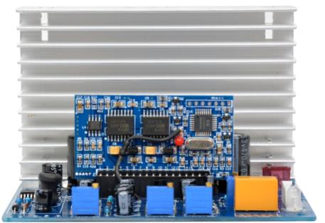
Remove this wire (and resistor too).
This wire controls the EG8010 output by pulling it's Ifb pin high enough
to switch OFF PWM output. And I don't want this function to be working either.
Edited by poida 2019-02-26
wronger than a phone book full of wrong phone numbers |
| |
BenandAmber
Guru
Joined: 16/02/2019
Location: United StatesPosts: 961 |
| Posted: 12:50am 25 Feb 2019 |
Copy link to clipboard |
Print this post |
|
Poida I am incredibly grateful
thank you so very much
I ordered a soldering rework station
I'm going to do it exactly how you did with the hot air
the other thing you was talkin about doing was adding protection
when you get a chance I would really appreciate it if you tell me what parts to order and how to do that also
Thank you again so very much
be warned i am good parrot but Dumber than a box of rocks |
| |
poida
Guru
Joined: 02/02/2017
Location: AustraliaPosts: 1480 |
| Posted: 01:32am 25 Feb 2019 |
Copy link to clipboard |
Print this post |
|
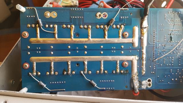
I now have a couple of photos of my board's protection.
Here is part 2:
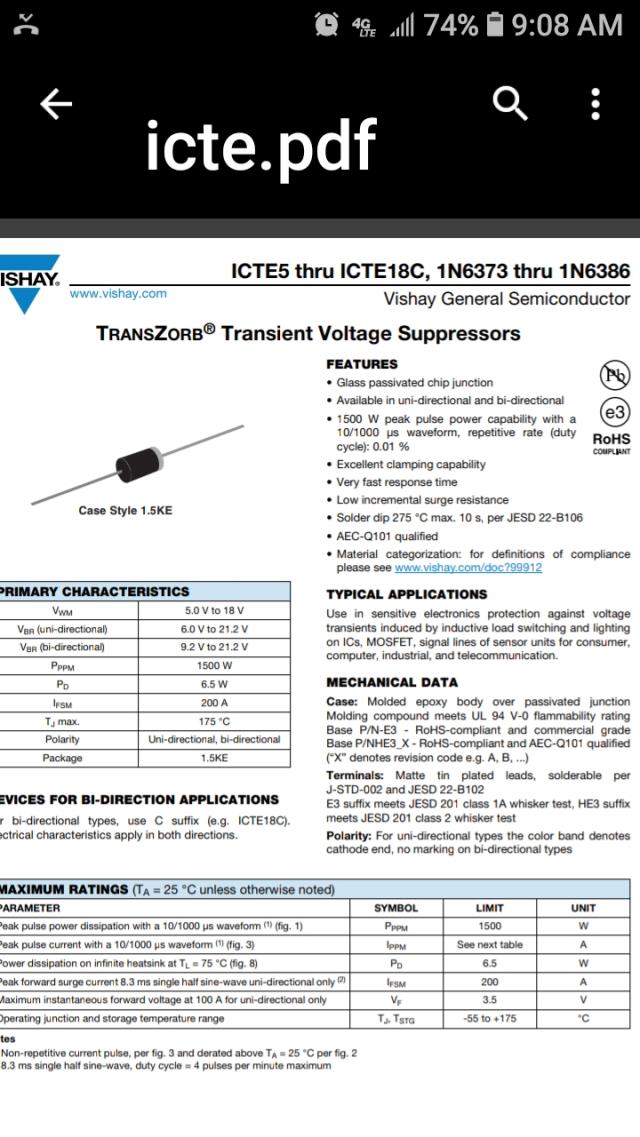
Obtain some 15V TVS devices. I think of these as good, strong, fast acting
zener diodes. They permit up to 18V to pass in one way, and very quickly clamping any voltage over this. And when voltage is flowing the other way, they are fast diodes, conducting the current, but with a small voltage drop of about 0.4V at the working currents.
RS part no. 815-2578
Vishay ICTE15-E3/54, Uni-Directional TVS Diode, 1500W, 2-Pin 1.5KE
AUD $0.92 each in a pack of 10
We want to protect the gate drive outputs of the IR2110 chips.
The manufacturer states all outputs must never go below about -0.3V compared with
ground or the high side "ground" which is the high side MOSFET's source pin.
Additionally, the specs say to never exceed 20V.
These 15V TVS diodes are about right for the job. Read the specs.
We only need 4, and we connect them near the MOSFETs, since that is where the potentially damaging voltages are generated. We connect each gate drive output to the corresponding MOSFET source pin.
In the case of my board shown below, I have 3 MOSFETS in parallel for each of the 4 legs of the full bridge. So I only need to do each leg of the full bridge, not all 12 MOSFETS.
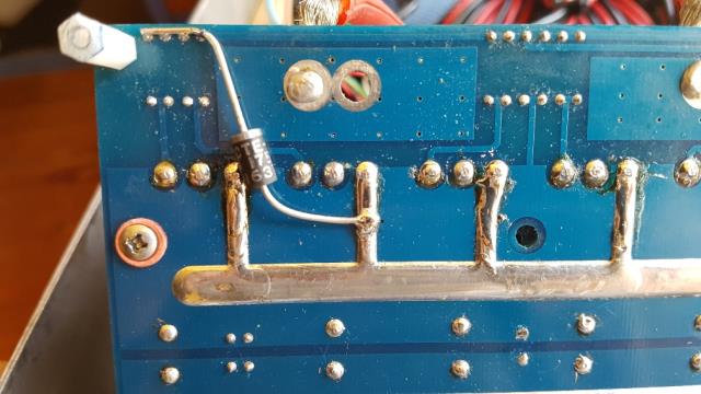
all 4 TVS in place:
a detail shot of one, showing polarity. Take care to fit these the correct way.
wronger than a phone book full of wrong phone numbers |
| |
poida
Guru
Joined: 02/02/2017
Location: AustraliaPosts: 1480 |
| Posted: 01:53am 25 Feb 2019 |
Copy link to clipboard |
Print this post |
|
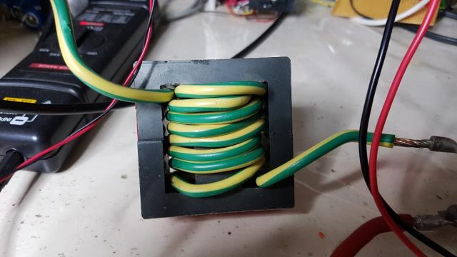
part 3, the choke:
Find a suitable and large ferrite E core.
I used one of these
https://au.rs-online.com/web/p/products/8407648/
stock no. 840-7648
It has a 0.5mm gap. Wiseguy correctly pointed out in another post of yours
my incorrect calculations.
Other people here have made their own, in different ways, using different cores.
We need something like 45uH, and the inductor (or choke) needs to still
work with currents well over 100A if you are planning to put 5000W through a 48V inverter.
You probably need 6 turns of the thickest cable you can fit.
You have an LCR meter? Handy to have but not mandatory.
No need to sweat over the value, 40 or 60 uH is good enough.
Here is one of mine. I used 6mm2 cable, 8 turns as you can see.
The LCR meter shows 46uH and in testing, it does not saturate until about 70A or so (from memory)
wronger than a phone book full of wrong phone numbers |
| |
BenandAmber
Guru
Joined: 16/02/2019
Location: United StatesPosts: 961 |
| Posted: 01:57am 25 Feb 2019 |
Copy link to clipboard |
Print this post |
|
Woohoo I figured out how to post a pic I had to send it through text message back to myself to get it the picture to be smallerEdited by BenandAmber 2019-02-26
be warned i am good parrot but Dumber than a box of rocks |
| |
BenandAmber
Guru
Joined: 16/02/2019
Location: United StatesPosts: 961 |
| Posted: 02:01am 25 Feb 2019 |
Copy link to clipboard |
Print this post |
|
Little practice board
be warned i am good parrot but Dumber than a box of rocks |
| |
BenandAmber
Guru
Joined: 16/02/2019
Location: United StatesPosts: 961 |
| Posted: 02:15am 25 Feb 2019 |
Copy link to clipboard |
Print this post |
|
be warned i am good parrot but Dumber than a box of rocks |
| |
BenandAmber
Guru
Joined: 16/02/2019
Location: United StatesPosts: 961 |
| Posted: 02:17am 25 Feb 2019 |
Copy link to clipboard |
Print this post |
|
The ESG egs002 board game with a short across two pins but luckily I had another one and I haven't powered it up so I should be able to fix thisEdited by BenandAmber 2019-02-26
be warned i am good parrot but Dumber than a box of rocks |
| |
BenandAmber
Guru
Joined: 16/02/2019
Location: United StatesPosts: 961 |
| Posted: 02:25am 25 Feb 2019 |
Copy link to clipboard |
Print this post |
|
Poida you are a lifesaver I appreciate you sharing your knowledge
I have a LCR meter on the way I've already ordered it
Meanwhile while I'm waiting on stuff to come in
this will give me a little bit of time to study and try to comprehend
I'm slow but I'm determined I will be doing mine as close to yours as possible
be warned i am good parrot but Dumber than a box of rocks |
| |
tinyt
Guru
Joined: 12/11/2017
Location: United StatesPosts: 561 |
| Posted: 04:12am 25 Feb 2019 |
Copy link to clipboard |
Print this post |
|
That ebay link allows the buyer to select only voltage and power, but frequency is not. I suggest that you download the EGS002 manual and study how the EGS002 is jumpered for. I believe you need it jumpered for 60Hz. |
| |
BenandAmber
Guru
Joined: 16/02/2019
Location: United StatesPosts: 961 |
| Posted: 05:55am 25 Feb 2019 |
Copy link to clipboard |
Print this post |
|
Tinyt thank you for the info I'll check that out
be warned i am good parrot but Dumber than a box of rocks |
| |
BenandAmber
Guru
Joined: 16/02/2019
Location: United StatesPosts: 961 |
| Posted: 05:57am 25 Feb 2019 |
Copy link to clipboard |
Print this post |
|
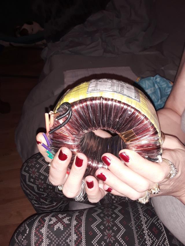
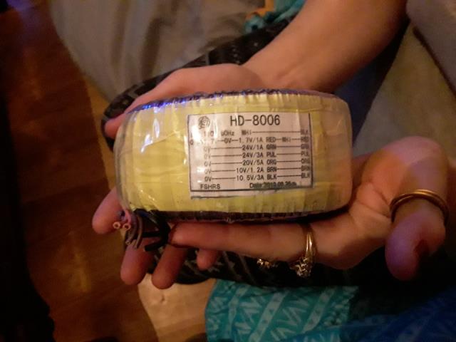
I thought about rewrapping a couple of these to run this test board or maybe I can use them the way they are I'll post another pic of your tag
be warned i am good parrot but Dumber than a box of rocks |
| |
BenandAmber
Guru
Joined: 16/02/2019
Location: United StatesPosts: 961 |
| Posted: 05:59am 25 Feb 2019 |
Copy link to clipboard |
Print this post |
|
These are the ones I said I had a few extra for somebody needed
be warned i am good parrot but Dumber than a box of rocks |
| |
BenandAmber
Guru
Joined: 16/02/2019
Location: United StatesPosts: 961 |
| Posted: 02:18pm 25 Feb 2019 |
Copy link to clipboard |
Print this post |
|
Poida is this the right part it is from digikey
be warned i am good parrot but Dumber than a box of rocks |
| |
LadyN

Guru
Joined: 26/01/2019
Location: United StatesPosts: 408 |
| Posted: 09:12pm 25 Feb 2019 |
Copy link to clipboard |
Print this post |
|
Nice you figured how to post pictures!
I am interested in the hot air rework station you got. Try it out and let me know and I will order it too!
Edited by LadyN 2019-02-27 |
| |
| |
Page 1 of 6 |
