Notice. New forum software under development. It's going to miss a few functions and look a bit ugly for a while, but I'm working on it full time now as the old forum was too unstable. Couple days, all good. If you notice any issues, please contact me.
M Del Senior Member Joined: 09/04/2012 Location: AustraliaPosts: 155
Posted: 05:06am 26 Feb 2019
Copy link to clipboard
Print this post
Hi, some nice work coming together here.
Safety query, do you take your rings off when working with your boards etc powered up? Also the possible still live capacitors after disconnect etc. I know a not insignificant number of blokes with burns from just a wedding ring making contact to live wires and conections.
Not picking, just curious, too many years in work shops. Mark
BenandAmber Guru Joined: 16/02/2019 Location: United StatesPosts: 961
Posted: 05:11am 26 Feb 2019
Copy link to clipboard
Print this post
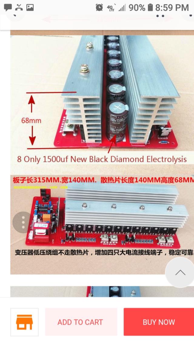
This is the big boy I planned on ordering and modifying the way that poida has instructed after I get the little board up and running and get the practice that I need this big 10000 watt board cost a little under $200be warned i am good parrot but Dumber than a box of rocks
BenandAmber Guru Joined: 16/02/2019 Location: United StatesPosts: 961
Posted: 05:18am 26 Feb 2019
Copy link to clipboard
Print this post
M Del my beautiful wife modeled for these pics and when she helps me she wears rubber gloves never takes her rings off only to clean them when she works on cars with her rings on she helps carrying firewood with our rings on she says she does everything a man can do but in stylebe warned i am good parrot but Dumber than a box of rocks
BenandAmber Guru Joined: 16/02/2019 Location: United StatesPosts: 961
Posted: 05:23am 26 Feb 2019
Copy link to clipboard
Print this post
You should see her winding a Transformer turn after turn after turn she thinks she always has to outdo me lolbe warned i am good parrot but Dumber than a box of rocks
noneyabussiness Guru Joined: 31/07/2017 Location: AustraliaPosts: 506
Posted: 10:43am 27 Feb 2019
Copy link to clipboard
Print this post
Just to add to poidas awesome post, solder bridge pins 7 and 8 where the op amp was... there is a 10k resistor to pull pin 6 high, but for security, this shorts it to 5v.I think it works !!
BenandAmber Guru Joined: 16/02/2019 Location: United StatesPosts: 961
Posted: 08:40am 07 Mar 2019
Copy link to clipboard
Print this post
Got a few things done did it exactly how the awesome really helpful nice guy told me to do it or the way I understood it anyway hopefully tomorrow I can talk Amber in to helping me finish winding the Transformer she starred on over a year ago thanks for your help everyone and a special thanks to Poida I couldn't do it without you guys Love peace good health and happiness to everyonebe warned i am good parrot but Dumber than a box of rocks
BenandAmber Guru Joined: 16/02/2019 Location: United StatesPosts: 961
Posted: 02:53am 08 Mar 2019
Copy link to clipboard
Print this post
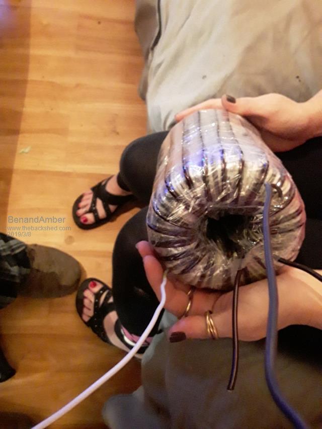
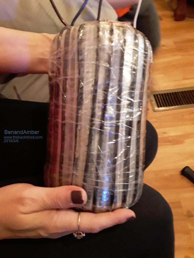
We got Amber's Transformer primary wound up and ready to go 10 gauge on the secondary and 3 gauge on the primary it's just what I had laying around being a electrician not too shabby for a quick job next is the wind the choke probably do that tomorrow maybe tonightEdited by BenandAmber 2019-03-09be warned i am good parrot but Dumber than a box of rocks
LadyN Guru Joined: 26/01/2019 Location: United StatesPosts: 408
Posted: 03:13am 08 Mar 2019
Copy link to clipboard
Print this post
Oh wow! This inspires me!
poida Guru Joined: 02/02/2017 Location: AustraliaPosts: 1389
Posted: 11:01am 08 Mar 2019
Copy link to clipboard
Print this post
When do you think you will fire it up? Again, it's not just a matter of building the big and only inverter you ever need and you move on... It's more like we make one or two, and by the time we make the 2nd or 3rd one, we have a good idea of what we are doing.
Things might not go well at first, but we all here can afford a few $$ for the next try so we keep trying. fingers crossed...
The TVS protection seems correct to me. I aligned the TVS diodes to allow up to about 15V going into the MOSFET gates and when the gate pin voltages are higher than the gate drive, to shunt or short circuit it to the MOSFET source pin. In my photo I posted earlier, I had the band end of the TVS connected to the gate drive and the other end (no band) soldered on the Source pin of each of the 4 legs. I think you got it exactly right.
Making your transformers is a satisfying thing. I did not do this, I used an already made one from a locally available grid tie solar inverter (Aerosharp 3kVA unit). It is all I need for my 1500W home system. I like how you built up a big one from a few smaller toroids. It will probably be useful but not capable of the 5kVA the mobile home of yours needs.
wronger than a phone book full of wrong phone numbers
BenandAmber Guru Joined: 16/02/2019 Location: United StatesPosts: 961
Posted: 09:02pm 09 Mar 2019
Copy link to clipboard
Print this post
Poida thank you for sharing your wisdom and kind words we need more people like you is this world with you guiding us we fill confident the Transformer Amber made I am hoping it will be good for 2000 watts it has 4 250 watt cores but they were medical grade and under rated I think
love happiness good health and peace to you poidaEdited by BenandAmber 2019-03-11be warned i am good parrot but Dumber than a box of rocks
BenandAmber Guru Joined: 16/02/2019 Location: United StatesPosts: 961
Posted: 09:20pm 09 Mar 2019
Copy link to clipboard
Print this post
Hopefully we get time today to build the c choke then were gonna try and fire it up fingers crossed and prayers go up itll work thanks for giving ben and I the inspiration and encouragement we needed to build one have a blessed day.Edited by BenandAmber 2019-03-12be warned i am good parrot but Dumber than a box of rocks
BenandAmber Guru Joined: 16/02/2019 Location: United StatesPosts: 961
Posted: 01:34am 17 Mar 2019
Copy link to clipboard
Print this post
Does anybody know if I can replace the four irf P290 7z mosfets on this little board with Hy 40 08 I should have a hundred of these on the way I was reading a post on here somewhere and somebody said that they were authentic gave the link so I went and bought them just in case I need them for the big boardbe warned i am good parrot but Dumber than a box of rocks
BenandAmber Guru Joined: 16/02/2019 Location: United StatesPosts: 961
Posted: 01:47am 17 Mar 2019
Copy link to clipboard
Print this post
We have gotten busy still haven't wrapped the choke We have put the 0.5 mm Gap in the e80 ecore Amber nor I can pick up the batterys to arrange them in 48volt series connection
She has had a few vertebrae removed out of her neck I have 9 bad vertebrae in my neck we broke are necks in different places and times both long storys she was fighting I was playing Evel Knievel
So that leads me to this I have a giant e Style Transformer would it be possible for me to wrap that for 48 to 50 volt output rectify and use it instead of batteries to test withEdited by BenandAmber 2019-03-18be warned i am good parrot but Dumber than a box of rocks
BenandAmber Guru Joined: 16/02/2019 Location: United StatesPosts: 961
Posted: 07:40pm 23 Mar 2019
Copy link to clipboard
Print this post
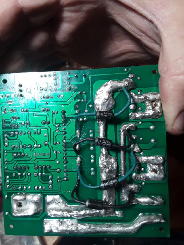
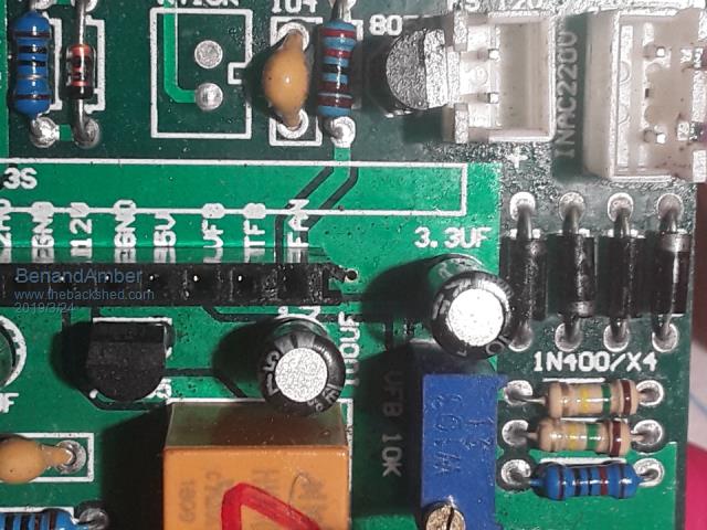
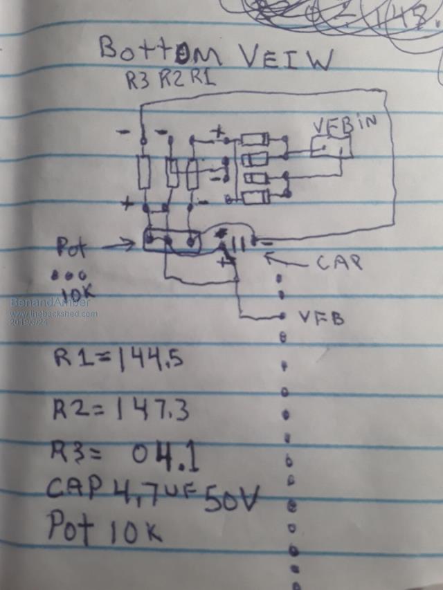
Top view Top view Top view Bottom View This is how I think the circuit works it's like it's got two paths for the voltage to go Bottom View
Bottom View
The two purple wires feedback from Transformer
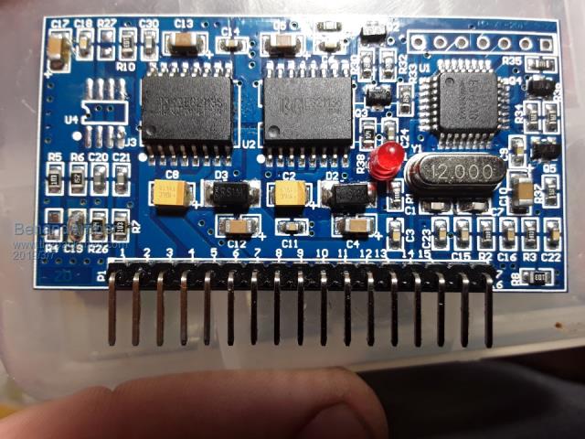
We are needing to change this board from 220 volt to 120 volt We are having a hard time trying to figure out if it's just as simple as changing the two resistors to half the value or if there's something more complicated going on I'm not showing any continuity between the two alike resistors so I don't think they are making a voltage divider unless I'm missing something here
Thanks everyoneEdited by BenandAmber 2019-03-25be warned i am good parrot but Dumber than a box of rocks
BenandAmber Guru Joined: 16/02/2019 Location: United StatesPosts: 961
Posted: 05:02am 24 Mar 2019
Copy link to clipboard
Print this post
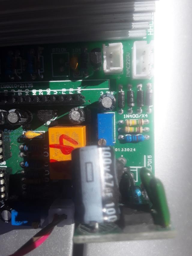
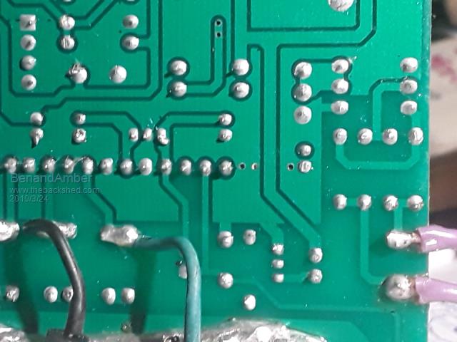
Bottom View
This is absolutely killing me I don't need to just have a fix for the problem I have to know how it works Thank you guys I appreciate it any input would be greatly appreciatedbe warned i am good parrot but Dumber than a box of rocks
wiseguy Guru Joined: 21/06/2018 Location: AustraliaPosts: 1000
Posted: 11:58pm 24 Mar 2019
Copy link to clipboard
Print this post
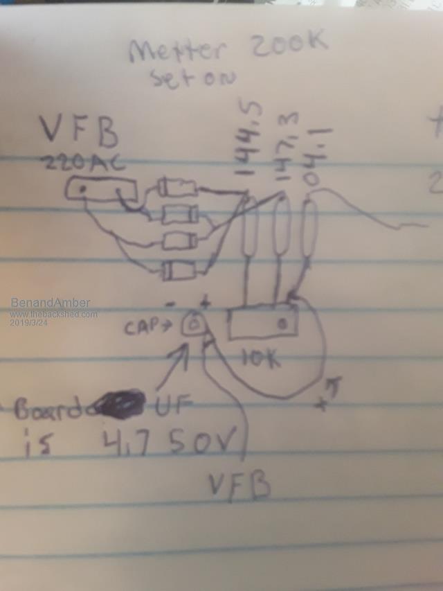
What transformer winding are the purple wires coming from - is it a winding from the main toroid or is it a separate transformer across the 220V output? Can you run the unit as a 220V inverter and measure the voltage across the purple wire connections what is it ? There are a few ways to achieve what you want but more information is needed. I gave up using the dedicated EG8010 chip in favor of the nano inverter controller but I can still try to help you.
If you havent powered up the unit that might be a good thing - see below.
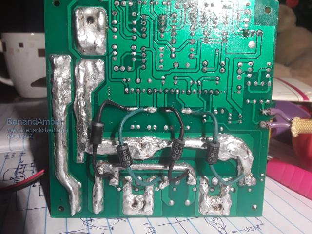
What are the four diodes under the PCB - are they transorbs ? If they are they dont look wired correctly to my old eyes. I am assuming they are to protect the gates of the output mosfets? The green anodes should not be connecting to the + supply but to the Drain to Source connection (big almost square sections with U shaped solder that join the LHS & RHS 2 mosfets together) ? Effectively join them to each FET between the gate and source (outside pins cathode (band) towards Gate) preferably with short wires.
For clarity, in the picture below the chinese eGS002 board (top of page) the rhs green connections need to both move down one connection from the drain to the source - can someone else please chime in if they agree I dont want to blow up Benn & Ambers board.?Edited by wiseguy 2019-03-26If at first you dont succeed, I suggest you avoid sky diving.... Cheers Mike
poida Guru Joined: 02/02/2017 Location: AustraliaPosts: 1389
Posted: 02:28am 25 Mar 2019
Copy link to clipboard
Print this post
I just now replied to your PMs regarding this question.wronger than a phone book full of wrong phone numbers
wiseguy Guru Joined: 21/06/2018 Location: AustraliaPosts: 1000
Posted: 05:47am 25 Mar 2019
Copy link to clipboard
Print this post
I'll sign off & leave you in Poidas good hands - I just did some calculations and realise that the two purple wires are obviously across the mains output directly.If at first you dont succeed, I suggest you avoid sky diving.... Cheers Mike
azhaque Senior Member Joined: 21/02/2017 Location: PakistanPosts: 117
Posted: 06:56am 25 Mar 2019
Copy link to clipboard
Print this post
BenAmber
You'll be doing the following if not already done
a) Make the following changes in the jumpers on the small EGS002 daughter board. 1. Change jumper for 120Volts 2. Change jumper for 60Hz from 50Hz
b) Add a small transformer 110/6 volts and adjust the pot to bring the voltage at 3 VDC at pin-15 of the connector where the egs002 board plugs in.
3.3 Jumper settings Designator Name Mark Setting Description 1 FS0 JP1 When JP1 is short, it selects AC output frequency at 60Hz JP5 When JP5 is short, it selects AC output frequency at 50Hz 2 SST JP2 When JP2 is short, it enables 3 seconds soft start mode JP6 When JP6 is short, it disables soft start mode 3 DT0 JP3 When JP7 and JP8 are short, dead time is 300ns. When JP3 and JP8 are short, dead time is 500ns. When JP4 and JP7 are short, dead time is 1.0us. When JP3 and JP4 are short, dead time is 1.5us. JP7 4 DT1 JP4 JP8 *5 LED+ JP9 When JP9 is short, LCD backlight is on When JP9 is open, LCD backlight is off The driver board�s jumperJP5, JP2, JP7 and JP8 are shorted as default setting, corresponding to 50Hz output, soft start mode on, 300nS dead time. Users can change these based on their needs. Warning: Jumper of the same function CANNOT be short circuited at the same time. (For example: JP1 And JP5 cannot be short at the same time.) Edited by azhaque 2019-03-26
wiseguy Guru Joined: 21/06/2018 Location: AustraliaPosts: 1000
Posted: 08:32am 25 Mar 2019
Copy link to clipboard
Print this post
I know I wasnt going to comment further but its hard enough making these things work ok without misleading or incomplete details:
What is the jumper on the EGS002 for 120V ??
What about the 2 x 150K resistors, they will need changing too. For a 6V transformer I calculate a value of 2K2 each as a reasonable starting point. If at first you dont succeed, I suggest you avoid sky diving.... Cheers Mike