
|
|
Forum Index : Electronics : Kent’s 10KW Inverter
| Page 1 of 4 |
|||||
| Author | Message | ||||
| kentfielddude Regular Member Joined: 09/05/2019 Location: United StatesPosts: 89 |
This is going to be my first inverter build. I'm going big or going home. I want to have 220v and 120v output on the toroid. I please need some help with the calculations for modifying/rewinding the toroid. I have the datasheet for the toroid but not for the core. 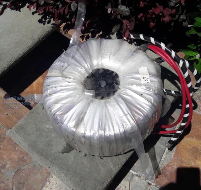 2019-07-13_130146_9540.pdf |
||||
| Warpspeed Guru Joined: 09/08/2007 Location: AustraliaPosts: 4406 |
As it is now, no load current (at 240v) is 505mA or 121 watts. That is is 2.9 Kwh per day loss just in idling power. What are you trying to do exactly ? Cheers, ĀTony. |
||||
| kentfielddude Regular Member Joined: 09/05/2019 Location: United StatesPosts: 89 |
I want to make an inverter to power my house. So I need two 120v legs with a neutral so I can get 220v and 110v Do you think I can rewind it to get lower losses? |
||||
| Clockmanfr Guru Joined: 23/10/2015 Location: FrancePosts: 437 |
Hi kent, I have built 8kW Ozinverters where the toroid is about 32Kg of bare core and fully wound toroid at about 50Kg. 6kW running and your bare core wants to be about 18kg to 22kg. Its all about mass in the core for long term power pulling, that's if your batteries can handle that drain. After many years of running, I do not recommend the 8kW as the 6kW can cope with everything I throw at it. As Warpspeed says the bigger the core the more power from your batteries is wasted just idling away. In general 20w to 35w for the 6kW Ozinverter and 40w to 80w for the my 8kW OzInverter. Above a 8kW toroid the weights become serious and assistance is required just to turn the toroid with out damaging it, enamel/insulation, mylar, joints etc. Toroid/Inverter ratings in the real world.,.... When I mean 6kW I mean 6kW all day if need be, (watch your batteries) with good cooling, runs happy at 15kW for some time, fantastic surges to 50kW, according to Oztules, I have not tested to that as I am a chicken! I once bought a well known make of top brand Inverter that said it was 6kW, in real life it would run at 4.5kW, at 6kW it would run for maybe 10 minutes before overheating and auto shut down. Below block diagram of a split phase for 120vac and 120vac. please ensure that your breaker is linked and shuts down the other breaker at the same time. 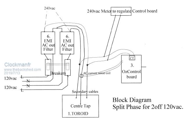 Everything is possible, just give me time. 3 HughP's 3.7m Wind T's (14 years). 5kW PV on 3 Trackers, (10 yrs). 21kW PV AC coupled SH GTI's. OzInverter created Grid. 1300ah 48v. |
||||
| kentfielddude Regular Member Joined: 09/05/2019 Location: United StatesPosts: 89 |
If I run a high voltage battery bank say 120v dc will that reduce idle load ? |
||||
| Warpspeed Guru Joined: 09/08/2007 Location: AustraliaPosts: 4406 |
Yes you possibly can. Lowering the flux density will reduce idling losses, but it requires more turns to do that. If it was just for 220v only, adding some extra turns to the secondary would be fairly easy. But you will require an exact centre tap for 110v/110v. That requires a complete removal of the secondary so a known number of turns tapped in the middle can be wound back on. How easy that is going to be, depends on how it has been wound. If the secondary is one single winding of massively thick wire its going to be a real problem. If there are multiple thinner strands wound in parallel it will be much easier, and the extra total wire length will be an advantage. Cheers, ĀTony. |
||||
| Warpspeed Guru Joined: 09/08/2007 Location: AustraliaPosts: 4406 |
No. Watts are watts. If it was for 12v dc, it would draw about 10 Amps idling power (120 watts) If its for 120v dc, then maybe 1 amp idling power, still 120 watts. Cheers, ĀTony. |
||||
| kentfielddude Regular Member Joined: 09/05/2019 Location: United StatesPosts: 89 |
Hmm. Well I'm not sure what to do anymore. This is the only toroid I have. Maybe 120w idle is okay if I have massive battery bank and lots of solar. |
||||
| Warpspeed Guru Joined: 09/08/2007 Location: AustraliaPosts: 4406 |
Well you can always build your inverter and revisit the toroid question later on. Cheers, ĀTony. |
||||
renewableMark Guru Joined: 09/12/2017 Location: AustraliaPosts: 1679 |
If it were me I would just make it, get something running and look around for a bare core to wind a nice one yourself. 3kw to waste a day is quite a lot. my whole house uses only 6 or 7kwhr a day, if we use the electric oven it can be around 10kwhr. Cheers Caveman Mark Off grid eastern Melb |
||||
| tinyt Guru Joined: 12/11/2017 Location: United StatesPosts: 561 |
My recommendation is to rewind the toroid transformer for lower idle power loss. If you have a variac and AC ammeter, AC voltmeter, power the 240vac winding at lower voltage and see at what voltage the winding have to 'see' for a lower idle power loss and work your winding calculations from there. Not sure if it will help but here is how I did mine. I was lucky that the transformer I got has low idle power to begin with. |
||||
| johnmc Senior Member Joined: 21/01/2011 Location: AustraliaPosts: 283 |
According to the pdf description , The wire used in both primary and secondary is 5awg which is ~ 4.5 mm dia and ~ 16mm sq which will be difficult to man handle . The steel used can always be used to make what ever core size you want. Many options depending on what you size inverter you require, and your battery bank. cheers john johnmc |
||||
| BenandAmber Guru Joined: 16/02/2019 Location: United StatesPosts: 961 |
He got a really good deal on that toroid he got it cheaper than what you could get a smaller one He could always make the Transformer a little bit smaller if he wanted to He's going to have to rewind it anyway so he can make it any size he wants The Transformer is a massive hundred and forty-four lb he really has to Transformers there And used solar panels are 20 or $25 a piece where he lives And he also can do like warp speed says to do to I think it lower the Tesla by rapping more Turns on it And I would guarantee you that the metal core of that Transformer is the best metal you can get I have been eyeballing that exact same transformer for a year-and-a-half I even offered the people twice as much as what he paid for it before I came across the 52-pound one I'm using now The people would never respond to me In my opinion he's very lucky and he can either have two very big transformers 3 good size ones or one gigantic one and have to buy an extra battery extra solar panel to make up for losses He is a engineering student and this is hands-on experience for him I think it's just wonderful I think he will come up with something fantastic It is the people just like him that is the future of this world we live in I have three young boys that will be living in the same world so I'm going to cheer him on all the way There is so much wisdom on this form that he could learn from there is some of the world's greats on here and this is exactly where that young man needs to be be warned i am good parrot but Dumber than a box of rocks |
||||
| Warpspeed Guru Joined: 09/08/2007 Location: AustraliaPosts: 4406 |
John, I read that as just being for the eighteen inch long tails. The actual windings themselves may be multiple strands, the way most of the grid tie inverters toroids are wound. What I am thinking, is that the secondary may be for instance four strands. That could be rewound as three strands with 33% extra turns with a centre tap using the original wire. That would create the extra turns without taking up any more space on the core. Max continuous rated power would reduce to 3/4, but 7.5Kw continuous is still a lot. As Clockman says, it will easily do multiples of 7.5Kw for short bursts. As it now is, the idling current is supposed to be 504mA. Try running it at 3/4 of that voltage (180v) off a variac, and see by how much the idling current falls. I would expect it might drop to one half or even less. The massive turn on current surge will greatly reduce as well. Cheers, ĀTony. |
||||
| kentfielddude Regular Member Joined: 09/05/2019 Location: United StatesPosts: 89 |
Ok. I'll give that a try. I don't have a variac but I can test with 110V. |
||||
| BenandAmber Guru Joined: 16/02/2019 Location: United StatesPosts: 961 |
You're awesome warpspeed I have a feeling no matter how it goes he will be very happy be warned i am good parrot but Dumber than a box of rocks |
||||
| kentfielddude Regular Member Joined: 09/05/2019 Location: United StatesPosts: 89 |
I'll take off the outer Mylar and upload some more pictures |
||||
| tinyt Guru Joined: 12/11/2017 Location: United StatesPosts: 561 |
May I suggest that before you do the 110V testing on the 240V winding, first add about 20 turns test winding using any type of insulated wire you have on hand (magnet wire, lamp cord, speaker wires, etc.). Connect this test winding in series (in-phase) with the 90v winding. Connect the 240v to the 110v source. Measure the voltage across the 90v winding. My guess is it will be around 41 vac and together with the test winding, it should be higher than 41vac when connected in-phase. If it is higher than 50vac then you can disconnect the 110v source from the 240v winding and connect it across these two (90v + test) windings. Since you know the test winding number of turns and can measure the voltage across it, you can now figure out the turns/volt or volts/turn of this transformer. With an AC ammeter you can now measure and calculate idle power loss at this test condition. And if you add more turns to the test winding and re-measure/calculate, you can figure out what turns/volt is needed to lower idle power loss. Not sure if it can be made lower than the specified core loss. |
||||
| Warpspeed Guru Joined: 09/08/2007 Location: AustraliaPosts: 4406 |
Its a very good idea to do some preliminary testing and write down all the figures you measure before pulling it apart. These figures may or may not be useful later on, but at least you will have the option. Cheers, ĀTony. |
||||
| BenandAmber Guru Joined: 16/02/2019 Location: United StatesPosts: 961 |
How is your Transformer doing have you made up your mind what you're going to do yet And have you received the $0.60 h y 4008 package yet Thanks again for Designing that little PCB from me also be warned i am good parrot but Dumber than a box of rocks |
||||
| Page 1 of 4 |
|||||
| The Back Shed's forum code is written, and hosted, in Australia. | © JAQ Software 2026 |
