| |
  Page 5 of 5 Page 5 of 5 |
| Author |
Message |
Revlac

Guru

Joined: 31/12/2016
Location: AustraliaPosts: 1153 |
| Posted: 11:57pm 16 May 2021 |
 Copy link to clipboard Copy link to clipboard |
 Print this post |
|
That would be R57 I will bridge that one on the next board that is mostly assembled, I see you are putting some components on the underside of the power board.
Cheers Aaron
Off The Grid |
| |
shallowal
Regular Member

Joined: 26/07/2018
Location: AustraliaPosts: 58 |
| Posted: 08:13am 18 May 2021 |
Copy link to clipboard |
Print this post |
|
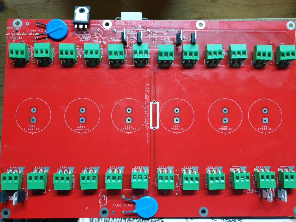
I decided to follow Warps build example for his inverter and use screw terminals to connect the FETs rather than soldering them in. PCB's dont like constant soldering/desoldering.
I set up my original board with the screw terminals, but had to have the screw heads facing towards the centre because the passives were in the way. I can get a long thin screwdriver through the gaps between the large caps once the heatsinks are off.
For this second powerboard I thought I would mount the passives underneath and then have the screw heads accessible. There's still some issues, but I think it will work much better.
 Allan Allan |
| |
Murphy's friend

Guru
Joined: 04/10/2019
Location: AustraliaPosts: 671 |
| Posted: 09:30am 18 May 2021 |
Copy link to clipboard |
Print this post |
|
These screw terminals are great until you have a blow up. Then you'll find the terminal is most likely too damaged to re use. You can guess how I know that.
I now use a different mosfet mounting method but its unsuitable for PCB's like the madboard. |
| |
shallowal
Regular Member
Joined: 26/07/2018
Location: AustraliaPosts: 58 |
| Posted: 10:04am 18 May 2021 |
Copy link to clipboard |
Print this post |
|
I've had a few blow ups already (not the board shown) and the screw terminals have proved their worth. Sometimes they're a bit blackened but that's the only damage I've had.
What other problems have you experienced with this system?.
Allan |
| |
shallowal
Regular Member
Joined: 26/07/2018
Location: AustraliaPosts: 58 |
| Posted: 10:11am 28 May 2021 |
Copy link to clipboard |
Print this post |
|
System seems to be running fine ATM with 4 FETs per channel. I just need to boost my battery size so that I can think about taking on the whole house.
I'm currently in the process of building up Poida's Nano-inverter, but it's a relief to at least have a relatively stable inverter.
A question that I hadnt considered until I struggled with the high output of my solar system and the backfeed through the inverter. When I fire up the inverter, the solar of course starts generating as per usual. However it is all too much for my small battery system, so I have to set about trying to manually curtail the solar to a reasonable level.
What is the common way to handle solar in this circumstance. Do you just leave it on the mains and run a separate charger to the battery, or use the likes of Mad's inverter controller. For those who are completely off-grid, how do you handle the high output solar?.
Allan |
| |
Murphy's friend
Guru
Joined: 04/10/2019
Location: AustraliaPosts: 671 |
| Posted: 02:03pm 28 May 2021 |
Copy link to clipboard |
Print this post |
|
Regarding screw terminals and blowups, yes they do survive a mild blow up. But once the source leg completely evaporates the terminal contacts seem to weld together and become useless. If there is a lot of blackening (carbonised plastic) I would not trust the terminal with 50+V DC.
A tip, should it happen to you. To unsolder these terminals from the PCB make a soldering iron tip that heats all 3 pins at once (a strip of copper bar) and then its easy.
Re the solar backfeed charging, I use that method a lot and have to 2KW solar back charging. The trick is to use a voltage sensing relay which trips once the battery voltage reaches a preset level. They have a settable re connect voltage so the relay does not chatter from battery voltage sag when the backfeed charge is turned off. I set mine 0.5V lower, that depends on the battery capacity a bit.
These relays run of 12VDC, I use a small transformer for that. For the actual charging switching, do that at the AC side (I use 30A mains rated relays, both A & N switched). Suggest you do not switch the solar DC, even with IGBT's. Mad once posted a schematic for that and I tried that, they did not survive long.
So I turn the AC connection between GTI and home built inverter on and off with the voltage sensing relay. The battery gets charged unregulated by whatever the solar panels can output, my lithium battery bank can handle that. If your battery bank is too small just feed less solar back charging in (fewer panels) and set the trip point accordingly.
Switching AC has been running for 2 years here with no problem. The lot fits in a plastic jiffy box.
I am off grid now. |
| |
nickskethisniks
Guru
Joined: 17/10/2017
Location: BelgiumPosts: 462 |
| Posted: 02:17pm 28 May 2021 |
Copy link to clipboard |
Print this post |
|
I'm using my mppt controller powerboard running poida's firmware code, in the code you can set a current limit, I have a big battery but it is set at 100A to protect the controller itself.
Is it an option to switch to something like that?
If you have already a battery charger maybe use that untill you have figured out what you expect from your system.
Madness made a pwm power contol board to control the power, or at least reduce the power going to the battery to limit the battery voltage. I don't think he measured the current, but I'm not sure. It it certainly hackable to also regulate the current. |
| |
| |
Page 5 of 5 |
