
|
|
Forum Index : Electronics : Allans Mad-Inverter Project
| Author | Message | ||||
| poida Guru Joined: 02/02/2017 Location: AustraliaPosts: 1388 |
Shallowal: If I was in the deep of problems you are with this project, I would first ensure the control board sends out clean gate drive signals. You will need to pull UP to about 12V the Vb pins of both outputs, I use a 1K resistor to 12V for that. Connect Vs to the control board ground. The 12V on Vb and Vs to ground gives the 8010 (high side) output drive something to drive. The low side drive takes the 8010 12V supply and drives that out it's outputs. Do not connect the powerboard yet. Give the control board enough so it starts up, put 24V or something on the incoming supply that feeds the 2 regulators. Then see all 4 waveforms of the 8010 output are correct and clean. The 8010 will run for a short while then stop due to undervoltage. This would be normal behavior. Once you know there is clean and correct outputs for both low and high side drives for both halves of the full bridge, then try the powerboard if you have rebuilt it and want to test it. I see you have the DS1054Z DSO. This is an excellent 'scope. I have one too. I find that there are about 100,000 different ways to pick up EMI or noise that mucks up the expected clean traces. I very frequently use "high Res" Acquire mode. This averages a heap of samples and then displays this average at that time location on the screen. It very effectively reduces the noise so you can see the underlaying signal. I would not expect much noise when testing the control board gate drive outputs without connection to a power board. But sometimes you want to see things a bit clearly so High Res is used a lot. If you want further info how I use mine I'd be happy to help in any way. Always remember that any and all inputs have their grounds connected together and this is connected to the 240 AC supply earth (AND Neutral). It's easy to blow sh!t up by hooking up ground clips to things. wronger than a phone book full of wrong phone numbers |
||||
renewableMark Guru Joined: 09/12/2017 Location: AustraliaPosts: 1678 |
Peter have you got my mad control card still? Maybe send that for Allan to test, since that is a proven unit. If he gets the same signals then just put caps in and power up. It's been a long time, but I don't think my wave looked very good at all without caps fitted, I think Allans one will be just fine. having a proven unit might be helpful for people to use in situations like this, I'm happy for that card to be used for that, as long as the recipient sends it on to the next person that needs it, or back to me or you. Cheers Caveman Mark Off grid eastern Melb |
||||
| shallowal Regular Member Joined: 26/07/2018 Location: AustraliaPosts: 58 |
Thanks Poida, I was gradually working backwards towards the control board after finally getting things working again. As I said earlier, I had a damaged (non) through hole on one of the powerboard FET's and some blown TIP41/42's. It also turned out that I had a faulty IR2010 which I had only just replaced so it was unexpected and took some time to discover. Mad's advice to use a resistive power supply made a considerable difference in enabling troubleshooting. I had been using a portable DSO Quad scope for years, but as the battery started failing I was leaving it plugged to a USB charger and one of my earlier attempts with the inverter caused it irreparable damage  . The decision to buy the 1054Z a few months back was a bit rash, but is a revelation in discovering what's really going on in my electronics. I am now paranoid about connecting anything "high voltage" to it . The decision to buy the 1054Z a few months back was a bit rash, but is a revelation in discovering what's really going on in my electronics. I am now paranoid about connecting anything "high voltage" to it  . . Would you mind stepping me through how you get to "High Res" Acquire mode?.  Allan Allan |
||||
| poida Guru Joined: 02/02/2017 Location: AustraliaPosts: 1388 |
You get High Res from the Acquire button. This is a setting is global for all 4 channels. Acquire has 4 choices, cycling in turn. Default is "Normal" This shows as best it can all the voltages that happened at each of the positions on the LCD. You can get a bit of a woolly trace from noisy sources. Next is "peak". This shows the max and min of a signal at each time position on the LCD. (there are 800 time positions minus the 2 menus, I suppose it's about 650 pixels wide then) Next is "average" You get to choose how many averages. 2 to 1024 averaged triggered traces are displayed. I find average to be good for very, very clearly triggered events. But for rapidly changing things it's wrong. Last is "High Res" which simply averages all the samples that fit within the time location together and plots the line of that average value at the time location. With maybe 3M samples and a timebase of 5ms/div that means we have 50M samples/sec The display is 12 divisions, and about 650 pixels wide so that's 54 pixels per division. 5ms/div means there will be 50M * 5 x 10-3 samples per division. This is 250000 samples per division. How on earth do you show all that? You average the 250,000 samples into 54 units and then display the 54 values at each of the 54 pixel locations within the division. The above numbers are not exact, just something that illustrates what's happening. I have my DS1054Z set to 5ms/div and Mem Depth = 3M samples. This is a good spot to get clean traces and a lot of pre-trigger history too. Here is my test inverter, a Mad 6kW totem pole power board with one MOSFET per leg, driven by the nanoverter control board. Dark Blue is AC voltage Yellow is the 50 Hz low side drive. (to get this, go Storage, picture, pic type is PNG, Save, disk D, new file, save..) Just use a smallish usb thumb drive. Most work fine. 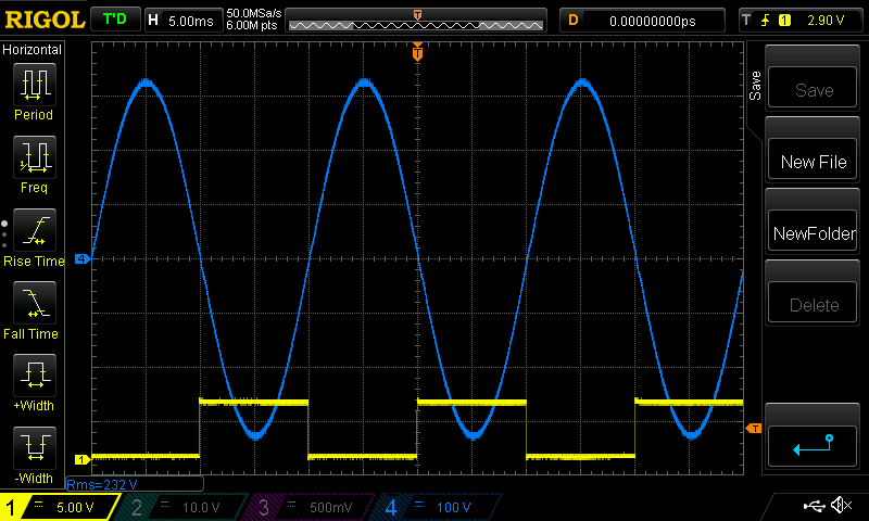 I have been free and easy with buying test gear. I use all the time a high voltage isolated probe. This is used to give me the AC voltage. This way the signal is in no way connected to the AC high voltage output. The probe is a Pintek DP-25 ebay link here You can do it too but you need to be really careful and I do not want to have anything to do with probing 240V AC RMS with earthed connections. wronger than a phone book full of wrong phone numbers |
||||
| poida Guru Joined: 02/02/2017 Location: AustraliaPosts: 1388 |
I need to find it and test it. Probably a weekend job. I recall it worked perfectly. But you had to feed it 240V AC output into some large exposed terminals so I used heaps of tape to cover the dangerous bits when I tested it. This could be a good thing to do. Can I send things to you Shallowal using the same address I used for the mppt boards? wronger than a phone book full of wrong phone numbers |
||||
| shallowal Regular Member Joined: 26/07/2018 Location: AustraliaPosts: 58 |
Thanks Poida, Yep Address is the same, but its really not necessary. I think I'll be able to figure out the problem once I get the chips replaced. Thanks for the Scope instruction, I must say that I found it quite difficult to get the hang of and still only use the basics with the occasional extension when needed. But I guess that's the way we learn any new product. Do you know if its possible to use differential mode and turn off the individual probe traces. I found a youtube for an earlier version of the scope where he just turned the individual traces off with the front buttons, but if I do it with the 1054 then the diff trace disappears as well. Allan |
||||
| poida Guru Joined: 02/02/2017 Location: AustraliaPosts: 1388 |
It's not possible to have math function (eg ch1 - ch2) shown without showing ch1 and ch2. I tried to move one or both channels down or up out of the way and you loose the math trace. And, the math function trace looks like crap with heaps of noise. 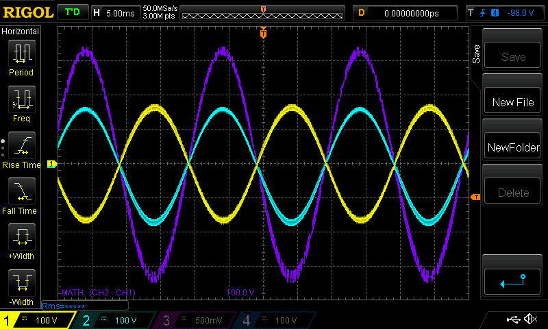 I had both probes set to 10x, vertical gain is 100V/div and had both ground clips clipped together but not connected to anything else. Yellow is ch1, Light Blue is ch2, Purple is math function (ch2 - ch1) wronger than a phone book full of wrong phone numbers |
||||
| shallowal Regular Member Joined: 26/07/2018 Location: AustraliaPosts: 58 |
Thanks Poida, that's pretty much the conclusion I had come to. I found that I could move the source traces out of the way and then press the math function again to bring focus on the diff trace, but it is annoying still, particularly when there is a lot of noise. Allan |
||||
| poida Guru Joined: 02/02/2017 Location: AustraliaPosts: 1388 |
here are the waveforms from first Mad's EG8010 based control board then the nanoverter. I did the two tests using the same powerboard, DC supply, toroid etc. It took about 20 seconds to change over control boards. EG8010: 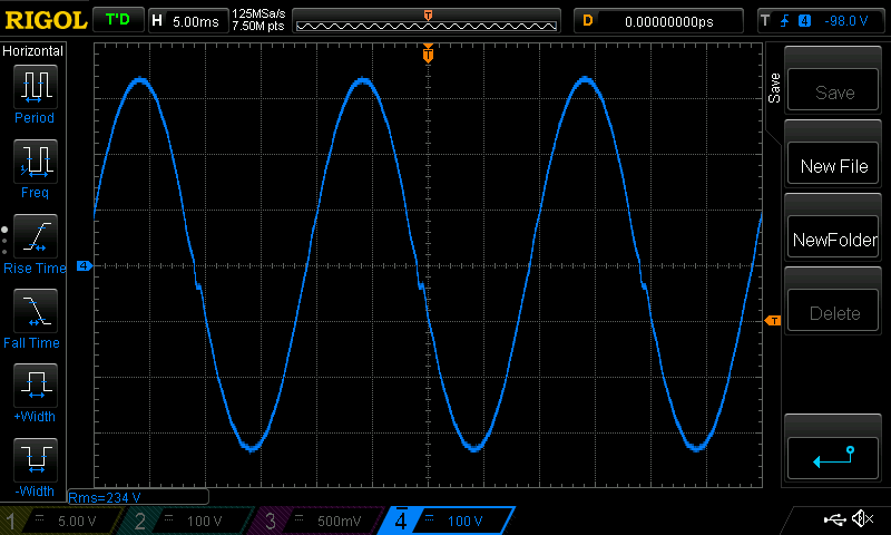 the nanoverter:  Idle current was 0.3A at 56V for the nanoverter and 0.34A for the EG8010 which also made some noise in the toroid. wronger than a phone book full of wrong phone numbers |
||||
| poida Guru Joined: 02/02/2017 Location: AustraliaPosts: 1388 |
If anyone may be thinking that some isolated high voltage probes for the oscilloscope might be nice, here is a comparison between the Pintek DP-25 and the rather old but still good enough Tektronix A6902B Isolator. Yellow is the Tek A6902B Dark Blue is the DP-25 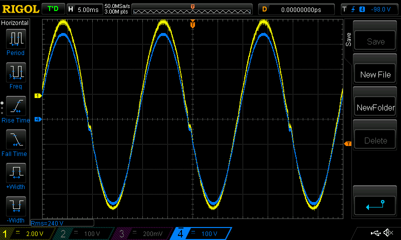 It appears the Tek is not so well calibrated. It is about 30 years old after all. The 239 V RMS from the Pintek was confirmed with the Fluke 87 DMM to within a volt or so. One channel only with the DP-25 but the Tek has 2 channels and some very high gain amplification available. Which brings heaps of noise to the output alas. Both offer a really safe way to see high voltage waveforms. Edited 2020-07-10 18:39 by poida wronger than a phone book full of wrong phone numbers |
||||
| shallowal Regular Member Joined: 26/07/2018 Location: AustraliaPosts: 58 |
Just replaced the EG8010 chip on the carrier board. Doesnt look quite as good as the original that I did, but after a couple of attempts at getting ALL the pins soldered  , I didnt have any shorts or disconnects and upon installation it all appears to be functioning. , I didnt have any shorts or disconnects and upon installation it all appears to be functioning.Now to verify that I have clean waveforms before venturing out into the 'unprotected' world again. Allan Allan |
||||
| shallowal Regular Member Joined: 26/07/2018 Location: AustraliaPosts: 58 |
Havent posted for a while as other projects have made it difficult for me to focus on getting the inverter running smoothly. I did have a time where I had populated the pwr board with 20 FETS and it was running well for a couple of multi hour sessions. And then. it just stopped. Couldnt look at it until a couple of months back and discovered a faulty cap had shorted out the 5v rail.  Subsequently I managed to insert the EG8010 upside down and blew 20 FETS .After recovering from that event... I now have a replacement EG8010 installed, but for some reason it wont start up when the 48v is applied. It'll start fine in either run or standby mode if I reset the 5V power (I briefly short the 5.6v zener). If I leave it powered up, the output SPWMOUT pins will drift until all the FETS turn on AND.....bang. I've checked the IFB/VFB/TFB pins and even tried shorting them to ground. Any ideas?. Plan B at the moment is to restart with Poidas nano-inverter board. Allan Allan |
||||
Revlac Guru Joined: 31/12/2016 Location: AustraliaPosts: 961 |
Hi Allan, Sorry to see its not working out for you. I would remove the nano (temporarily) and check everything thoroughly, there is a fault or 2 somewhere, sometimes hard to find, the design works well. I have to ask, have you changed R44 and R46 on the power board, to 5K1 ohm? Probably have or it might not have made it this far. Cheers Aaron Off The Grid |
||||
| shallowal Regular Member Joined: 26/07/2018 Location: AustraliaPosts: 58 |
Thanks Aaron, I already tried without the nano and also bypassing the 120 ohm resistor and removing the IR2010's. With the control board disconnected from the power board I have tried various voltages and startup sequences, but the only success is to delay or reset the 5V bus. Those resistors are 5K1. It seems very odd, so I have ordered some 32 pin LQFP to DIL adapters and I'll try a replacement EG8010. Allan |
||||
| Revlac Guru Joined: 31/12/2016 Location: AustraliaPosts: 961 |
I agree it seems quite odd. Sounds like something is holding it low preventing startup, worth trying another 8010 chip to see if anything changes, there are a few different versions, but they should still work. I went over the 8010 carrier board several times with a large magnifier and lamp to check all the joints, give a few of them a touch with a hot soldering iron to tidy up a few until I was satisfied. I have 2 control boards assembled ATM, 1 has been tested and working the other (for another build) I haven't tried yet, will have a look at it when I have some spare time. Cheers Aaron Off The Grid |
||||
| shallowal Regular Member Joined: 26/07/2018 Location: AustraliaPosts: 58 |
Got my new carrier boards and soldered up an 8010, only to discover that the Mad board row spacing is odd at 0.7 inch, rather than the standard 0.6 inch.  Tried the new chip/carrier by bending the connector strips to suit the new (narrow) board and it fired up straight away, but for some reason it would shut off with over-voltage but not under-voltage. I wasnt game to plug it into the power board and blow up FET's, so plan B. Plan B... Soldered another 8010 onto the original carrier board and all was good. I can only assume that there was some resistive or capacitive connection when I soldered up the first 8010. All good ATM with 2 FET's per channel, so I'll do some more testing and continue building up the nanoinverter control board and new power board in the meantime. Allan |
||||
| shallowal Regular Member Joined: 26/07/2018 Location: AustraliaPosts: 58 |
Power outage today, ideal opportunity to try out the inverter. Seems OK ATM, but most of the power is being supplied by solar. At least the battery is getting charged . Allan |
||||
| Revlac Guru Joined: 31/12/2016 Location: AustraliaPosts: 961 |
Sounds like a good result, it's encouraging that it is working, The batch of 5, eg8010 chips I had, 4 of them have tested ok, the last one needs to be put on the carrier. A power outage will usually confirm why we do these things, then when running off grid, then the neighbours drop in to tel us about the power outage that lasted all night and couldn't pump water to have a shower, then they ask how did you get on with that? I Never noticed it. They asked that a few times at the beginning, they don't ask anymore.  Cheers Aaron Off The Grid |
||||
| shallowal Regular Member Joined: 26/07/2018 Location: AustraliaPosts: 58 |
Ha ha !!, so true Aaron. Our local solar guy is off grid and always rubs it in after one of our frequent outages. Allan |
||||
| shallowal Regular Member Joined: 26/07/2018 Location: AustraliaPosts: 58 |
Building up another MAD power board and while checking for any errors I notice that one of the 'H' bridge legs showed a different resistance between the Grid and Source FET legs. 3 of the channels showed 2015 ohms, but the fourth showed 2440 ohms. Turns out there is a fault in the board layout which leaves one of the 20k resistors floating. In the photo I have started scraping off the solder resist to bridge the connection. 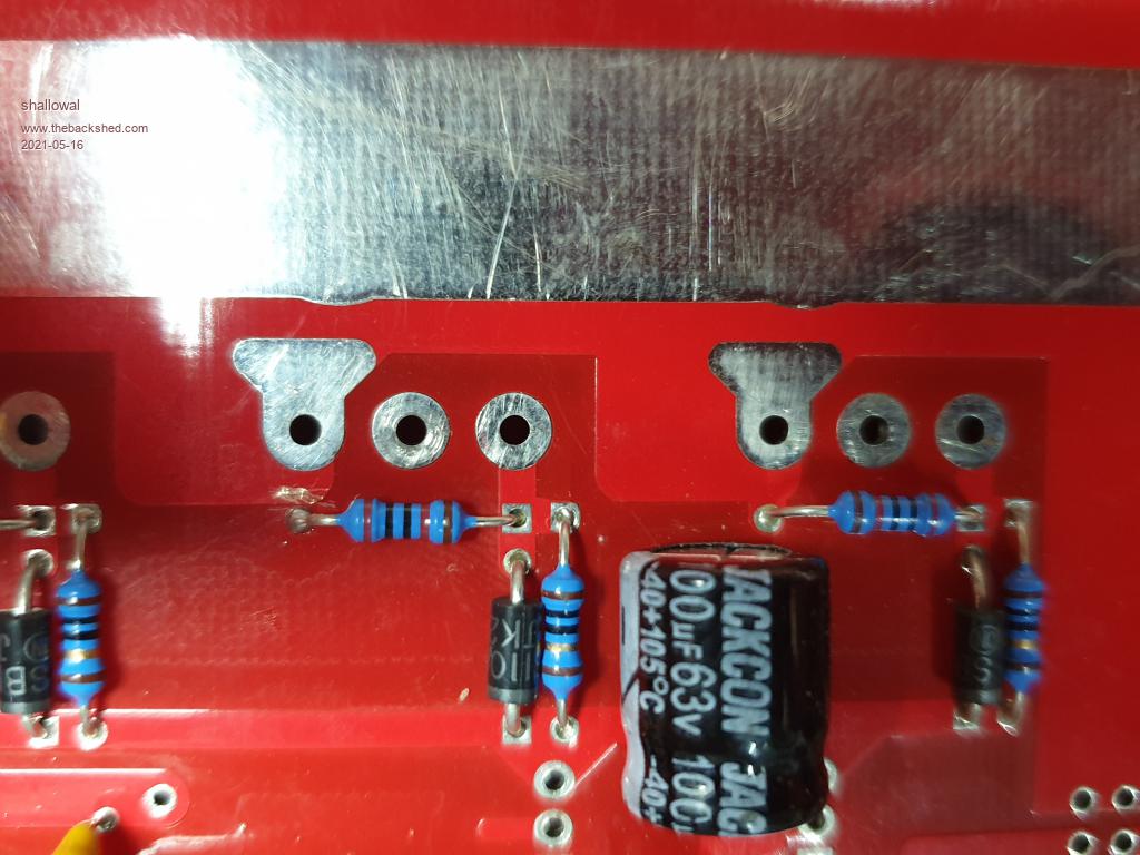 Allan Allan |
||||
