
|
|
Forum Index : Electronics : EG8010 driving IGBTs frequency questions
| Page 1 of 2 |
|||||
| Author | Message | ||||
Haxby Guru Joined: 07/07/2008 Location: AustraliaPosts: 426 |
Hi all, I'm considering using an IGBT module that is 150A, 700V and includes onboard driver chips and 3x half bridge drivers onboard to be controlled by the EG8010 for a compact but powerful inverter. The IGBT module I have says 20khz max but the eg8010 is 23.4khz I'm thinking that it won't be a problem since the actual output on/off time of the 8010 will always be longer than 23.4 kHz? Is that correct? |
||||
| Warpspeed Guru Joined: 09/08/2007 Location: AustraliaPosts: 4406 |
Its difficult to set a precise frequency limit, its not a case of working perfectly at 19.9 Khz and not working at all at 20.1 Khz. Switching losses increase both with frequency and voltage, and at some point its going to become very hot, highly stressed (thermally) and inefficient, and just impractical. If the pwm frequency is 23.4 Khz, it has to switch on and off at that rate, regardless of the duty cycle. It will probably work in a fashion, but I would not do it that way myself. I suspect your zero load idling current is going to be rather high, not only from the high switching losses. Discharging and charging stray capacitance at such a high voltage and switching frequency is going to soak up power that ultimately has to come from the battery. In something like a variable frequency motor drive, the motor may be rated at say 30Kw, and 200 watts of switching loss is insignificant. In an inverter, a constant 200 watt load running for 24 hours consumes 4.8 Kwh per day. That might be greater than your daily domestic load ! No load idling power is a very big issue with an inverter, its a special application that requires a different approach. Cheers, ĀTony. |
||||
| poida Guru Joined: 02/02/2017 Location: AustraliaPosts: 1480 |
I found that I could drive the EG8010 with nearly any frequency during experiments with the chip. I used a function generator to provide the clock. So just choose a crystal that gives the PWM frequency you want. There is a post here on this forum showing what I did. here wronger than a phone book full of wrong phone numbers |
||||
| Warpspeed Guru Joined: 09/08/2007 Location: AustraliaPosts: 4406 |
Just re reading through that old thread, there is some really good stuff in there  Cheers, ĀTony. |
||||
| Haxby Guru Joined: 07/07/2008 Location: AustraliaPosts: 426 |
Pioda that's a good thread and I appreciate that a slower crystal will decrease the PWM but I want to keep the 50Hz the same. Surely that is dependent on the original crystal frequency? |
||||
| poida Guru Joined: 02/02/2017 Location: AustraliaPosts: 1480 |
You can use the variable output frequency control. The incremental changes were rather large for my purposes (sync to mains) I did it here So get a slower crystal, to give a less than 20kHz pwm and then adjust the output freq to give what you need to some near enough value. It might be worthwhile to keep in mind the Australian electricty grid has frequency standards that consider "OK operating conditions" to be between 49.5Hz and 50.5Hz. This implies to me that nearly everything we plug into mains 240V can run fine within this wide range of freq. Edited 2020-07-18 14:58 by poida wronger than a phone book full of wrong phone numbers |
||||
| Warpspeed Guru Joined: 09/08/2007 Location: AustraliaPosts: 4406 |
Haxby, I hardly dare suggest this, but have you considered building a Warpverter? This combines the outputs of four LOW FREQUENCY square wave inverters to generate a low distortion sine wave. Its really direct digital to analog conversion on steroids. The advantage of this is, you can use a high voltage dc source, and fairly big and slow IGBTs to hard switch the primaries of four different transformers. The secondary voltages when combined in series will create a sine wave of less than 1% total harmonic distortion, and voltage regulate over a 2:1 dc input voltage range. This is something of my own creation, but there are now five Forum members here that have successfully built inverters of this type, and all are in the 5Kw to 7.5Kw range. PWM is perfect for low voltage off grid operation up to about 5Kw. The "Mad" inverter, derived from the original "Oz" inverter comes very highly recommended, and would be my personal preference for most typical off grid applications. At much higher voltage, or much higher power, the problems with high frequency pwm become much more difficult to solve. The Warpverter has many more parts, because there are four inverters not one, but for something pretty extreme, it will be much easier to get going reliably than pwm. 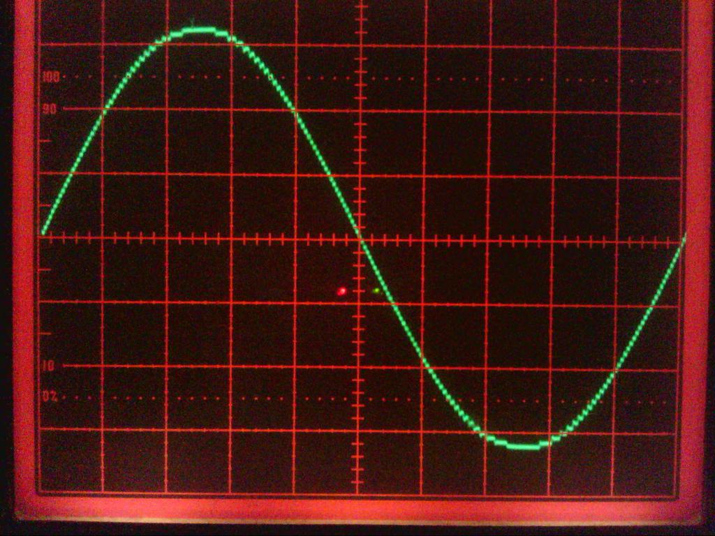 Cheers, ĀTony. |
||||
| Haxby Guru Joined: 07/07/2008 Location: AustraliaPosts: 426 |
I'm really interested in the warpverter. I just spent the afternoon piecing together the info found on this forum over the last year or so. Is there a web page that puts it all together? My aim is to run an off grid cabin from a Prius. I could also use the Prius to build said cabin. So it would need to run air compressors, and power tools. 5kw would be the aim. Maybe more... If I use the Prius battery pack that is 200v to 230v DC, what ratio transformers do I need? Also, I couldn't find a diagram of how the transformers connect together. Are the secondaries in series? |
||||
| Warpspeed Guru Joined: 09/08/2007 Location: AustraliaPosts: 4406 |
The primary windings of all four transformers are wound for whatever will be the minimum dc voltage the inverter will ever see. It will then work from that minimum input voltage up to twice that voltage. The secondary voltages will be 225v for the largest transformer, 75v for the second largest, 25v for the third largest and 8.33v for the smallest. The secondary voltages must go up in EXACT steps of three, and that is important. Secondaries are connected directly in series so secondary currents will be equal to the inverter rated current. Five Kw = 230v x 22 amps for example. Now at the minimum rated dc input voltage, if all the inverters switch on in the same direction, a voltage peak of 225 + 75 + 25 + 8.33 = 333.33v is possible. That would create a 235.7v rms sine wave at minimum dc input. Anything above minimum dc input, the voltage regulation kicks in, and the actual ac output voltage can be tweaked with a potentiometer. Here is the complete wiring diagram. As you can see, the secondaries are just connected in series, its that simple. 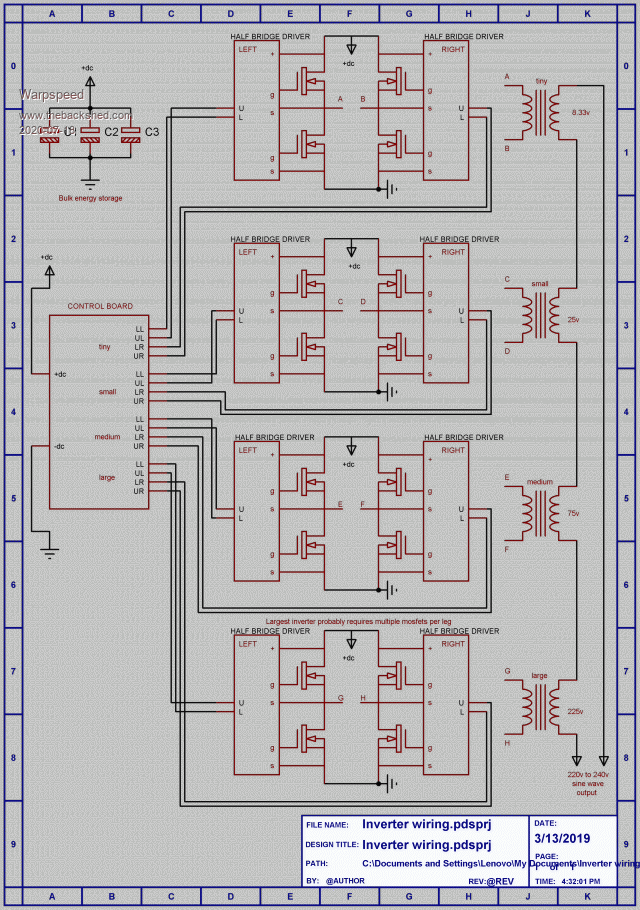 Cheers, ĀTony. |
||||
| Warpspeed Guru Joined: 09/08/2007 Location: AustraliaPosts: 4406 |
There are two different control boards available for this inverter, a hardware board (without a microprocessor) from me, and Mike has developed a Nano control board for this inverter. Both boards are directly interchangeable and are functionally identical and 100% plug compatible. There is no voltage feedback required, it uses feed forward compensation. As the dc input voltage goes up and down, different lookup tables are accessed to generate a constant output voltage. My board has 256 different lookup tables that cover a 2:1 input voltage change. There is a later improvement, not shown on the above diagram that adds current feed forward as well. As the output load increases, the dc input current also increases. This also steps to a different lookup table, preventing voltage sag under load. In fact you can tweak it so the output voltage actually rises as load increases if its adjusted to do that. The voltage and current corrections are very fast, without any possibility of instability, and all the gain switching is done at the zero crossings, so there are no waveform discontinuities. The inverter is completely bi directional, large out of phase currents, are handled with ease, and waveform distortion with nasty non liner loads remains minimal. Its all a bit odd and unusual, but is all proven to work very well. Cheers, ĀTony. |
||||
| Haxby Guru Joined: 07/07/2008 Location: AustraliaPosts: 426 |
That diagram doesn't look as complicated as I thought. Ok I'm in. I think this is the way to go. Let's talk transformers: In the diagram, the transformer values are peak values (not RMS) yes? My absolute lowest input voltage will be 190V DC. So I guess the next step is to find a whole heap of solar inverters and collect some toroids! No need for chokes in this design? |
||||
| Warpspeed Guru Joined: 09/08/2007 Location: AustraliaPosts: 4406 |
The transformers are quite interesting in themselves and are about 90% of the work required in building an inverter like this. Chokes need not apply for this job. These all switch square wave voltages, so the turns ratio reflects directly the dc supply voltage rail, and the required peak square wave voltage on the secondary. The largest transformer will be 190v / 225v. Secondary current 22 amps rms, so the largest transformer will be sized for 4.95 Kva. Recommended current density in the wire 4 amps per square mm. If the transformer is designed for 190v/225v rms and 50 Hz, with a design flux density of one Tesla (10,000 Gauss) it all becomes much easier to design. That is really a fiction, as it sees square wave voltage, but if its designed for rms, voltages and 50Hz it will work fine. The really fascinating thing about all this, is the transformer voltages are all square waves, but the current through all of the windings will be sine waves !! If you think the whole thing right through, its almost surreal what is actually happening in those four transformers. Anyhow, the second transformer will be 190v / 75v. Again secondary current 22 amps rms. The actual voltage waveform will look rather odd, its not 50Hz, but has higher frequency components. But if we design that too as if it was just an ordinary garden variety 50 Hz sine wave transformer with one Tesla flux density, it will work perfectly well like that. Third transformer 190v / 25v, and fourth transformer 190v / 8.33v, all designed for 50Hz rms sine waves. The whole thing is actually fairly simple, but there are a lot of individual parts which adds to the cost, and makes it look more complicated than it really is. The one big advantage of all this is that everything switches at a very low frequency, layout is non critical, and at higher dc voltages, single high power (but slow) IGBT power blocks can be used. ĀSo we can switch kilowatts, or tens of kilowatts with ease with just single quite slow switching devices. None of this trying to parallel up multiple mosfets and trying to get them all to switch a very high current simultaneously, and also current share, at 20Khz plus. That all works quite well at relatively low power, but it does not scale up very well. . Edited 2020-07-19 11:39 by Warpspeed Cheers, ĀTony. |
||||
| Haxby Guru Joined: 07/07/2008 Location: AustraliaPosts: 426 |
What half bridge driver do you use? |
||||
| Warpspeed Guru Joined: 09/08/2007 Location: AustraliaPosts: 4406 |
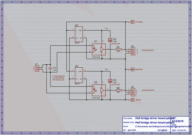 Pretty basic, I used eight of these same boards. 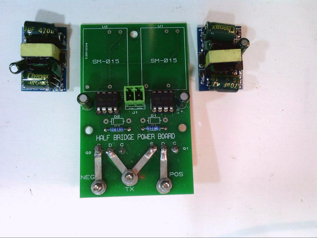 Cheers, ĀTony. |
||||
| Warpspeed Guru Joined: 09/08/2007 Location: AustraliaPosts: 4406 |
Four of these driver boards run the two smaller inverters that just use individual 50 amp 600 volt IGBTs or mosfets. 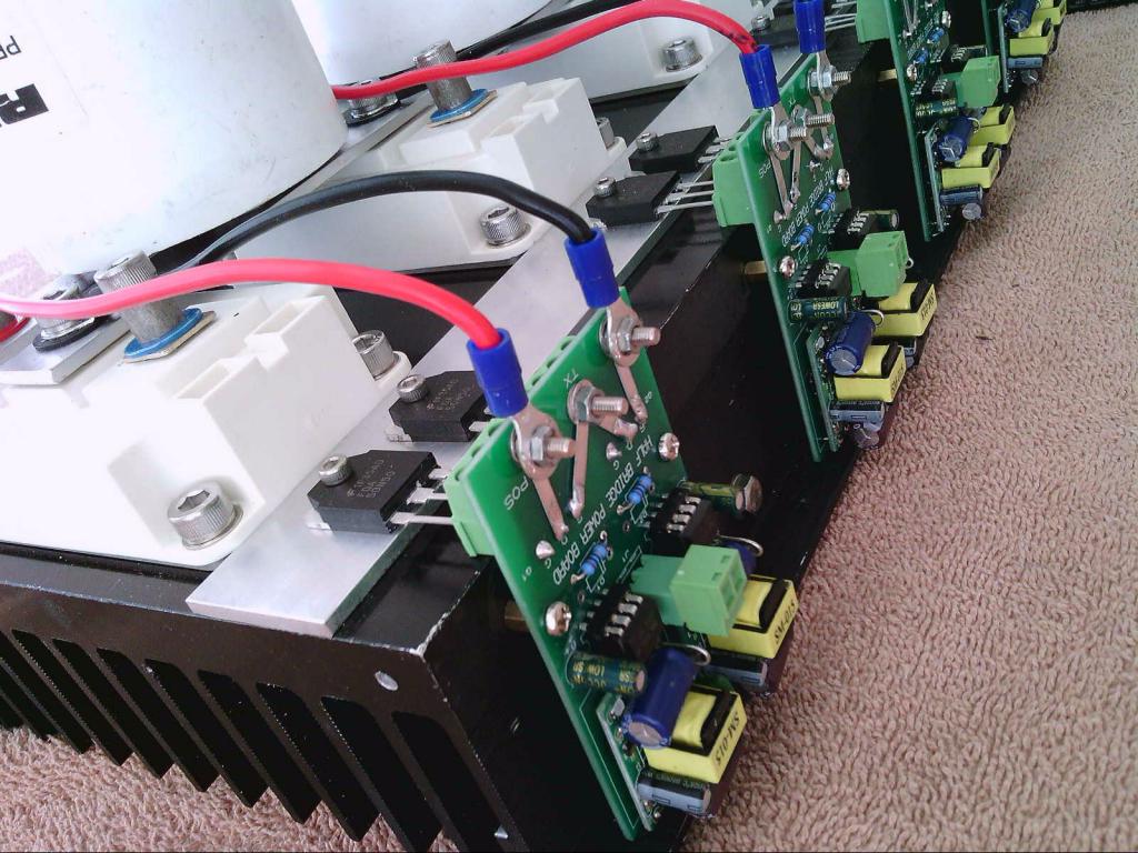 Four more driver boards run the two larger inverters that use 200 amp 1200 volt half bridge IGBT power blocks. 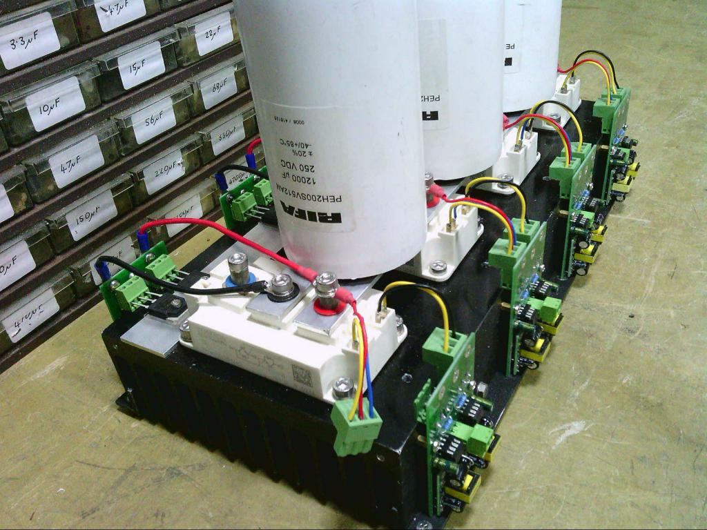 The control board (either type) sits on top of the electrolytics. This is my very simple basic "dumb" non microprocessor board. 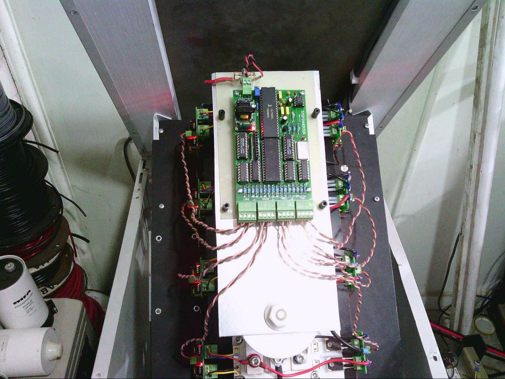 This is Mike's "smart" Nano board, it has a lot of extra features, and plugs straight in. 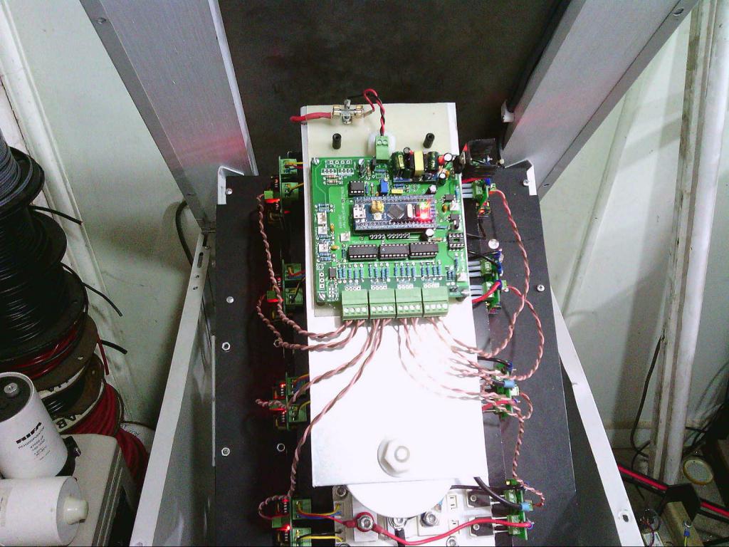 Cheers, ĀTony. |
||||
| Haxby Guru Joined: 07/07/2008 Location: AustraliaPosts: 426 |
That's a serious inverter! Looks like the SM-015 modules that drive each gate pair are no longer being sold. I'm sure I can find something that will do the job. I'll just daisychain the gate power supply from board to board so that I don't need 16 of them. Or on second thought, maybe I can spin my own single IGBT power handling board...hmmm. I've got a bit of time on my hands now. Where did you get your transformers? Do you have a spare programmed EEPROM and PCB you can sell? |
||||
| Warpspeed Guru Joined: 09/08/2007 Location: AustraliaPosts: 4406 |
No don't common anything ! I just realised the schematic does not correspond exactly to the board. The inverse diodes across the gate resistors are no longer required, and the component designators are wrong. But the schematic is correct in concept. The board pictured was the first batch that I am still using in my own inverter. The schematic is for the latest version boards that I am providing to others as Gerber files. Those SM-15 modules are actually the isolated 15v dc power supplies. Twelve volt versions are still readily available, but the 15v ones seem to have become extinct for some strange reason. https://www.ebay.com.au/itm/AC-DC-Power-Supply-Buck-Converter-Step-Down-Module-5V-12V-9V-24V-New/182287599227?hash=item2a7130067b:g:u6MAAOSwLnBX4S3O These are the guts out of common dc plug packs, made by the million in China. They operate from about 40v dc input up to 400v dc input or more, are voltage regulated, current limited, and fully galvanically isolated, and cost about $2.00 each. The isolation feature is VITAL for both noise immunity and isolating any blow ups to just the gate driver for a particular IGBT. If you start commoning up dc power supplies, one IGBT blows, and that will very likely propagate right around the system causing catastrophic damage. Likewise the opto isolators provide very high noise immunity, dead time, fool proof cross conduction protection, and also prevent a blow up from getting back into the control board, as well as providing an efficient undervoltage shutdown feature. The circuit looks very basic, almost primitive, but there are a lot of very worthwhile features contained in so few components that may not be immediately obvious at first glance. Edited 2020-07-19 18:54 by Warpspeed Cheers, ĀTony. |
||||
| BenandAmber Guru Joined: 16/02/2019 Location: United StatesPosts: 961 |
Can you use Square and toroid Transformers together Warpspeed? If so it there anything you would suggest? be warned i am good parrot but Dumber than a box of rocks |
||||
| Haxby Guru Joined: 07/07/2008 Location: AustraliaPosts: 426 |
OK I haveĀput up a wanted ad on facebook marketplace for Aero-Sharp inverters, with an offer to buy them for $100 dead or alive.ĀLooks like I will already have one by the weekend! I guess I should try to get 3 x 3kw toroids, and maybe a 1.5kw with the reasoning: 2x toroids for the large transformer 1x toroid for the medium transformer 1x 1.5kw toroid for the small transformer 1x something else cobbled together for the tiny transformer sound like a plan? |
||||
| Murphy's friend Guru Joined: 04/10/2019 Location: AustraliaPosts: 678 |
Good plan. it would help to state the city you are in, I have 1 x 3KW fully working and 1 x 1.5KW plain core here. Shipping is not an option. |
||||
| Page 1 of 2 |
|||||
| The Back Shed's forum code is written, and hosted, in Australia. | © JAQ Software 2026 |
