
|
|
Forum Index : Electronics : 3 phase inverter for AC induction and servo motors
| Page 1 of 5 |
|||||
| Author | Message | ||||
| poida Guru Joined: 02/02/2017 Location: AustraliaPosts: 1476 |
wronger than a phone book full of wrong phone numbers |
||||
| poida Guru Joined: 02/02/2017 Location: AustraliaPosts: 1476 |
(whoops, hit post before anything) Previous work with inverters has used one Arduino Nano to produce the PWM signal that is then sent to 1/2 bridge driver ICs that then make the low and high side gate drive outputs with deadtime. A 240V AC inverter needs 2 of the half bridge drivers and MOSFETS to produce the sinewave output. I have been playing with 3 phase AC and I found all I need is an Arduino Mega to give me the 3 PWM outputs. The Mega has a lot of timers suitable for the job and I use timer no. 1, 3 and 5. It is simple to generate the 3 SPWM (sinewave pulse width modulation) and to have them output 120 degrees phase difference to each other. There are already ICs that do this, the EG8030 but you and I know it's far more fun to do it yourself. And you get to control everything about the inverter behaviour. I have a couple of videos of this: first is showing the SPWM of the 3 outputs from the single Mega. I low pass filter the PWM to give a voltage so that it can be captured by the DSO I alter the frequency from 20 Hz down to zero then reverse direction and go to -20Hz Reverse direction Ā= negative frequency for this project. https://youtu.be/Xy5Er08NyLg and here is a video of the AC servo motor rotating. Speed and direction controlled by a pot. https://youtu.be/aqoJkCixJag There is not a lot to this. The breadboard is not ideal for 20KHz PWM but it works. I even made some code that takes the position sensor output from motor and ran it in position control, with closed loop feedback of position error driving the motor. The position encoder outputs 5V logic level quadrature signals which are easy to detect and accumulate counts. Aaron here is interested in a 3 phase inverter. I suspect he will build it with 3 similar toroids, with the AC outputs having one of the wires all tied together to make a Neutral, and P1, P2 and P3 outputs all at 240V AC 50Hz. I think I can do the firmware for this. Aaron wants some process control: - soft start and soft stop from zero to 240V 50Hz - reduce frequency when input voltage drops, in an attempt to lower the motor power draw. - Āuse the inverter to power a 3 phase water pump, driven by a standalone solar array, maybe with or without batteries. Already you can do this, just buy a cheap Chinese VFD. But we need to complicate our lives, to be spending lots of time developing projects. If we just go the easy and fast way, there will be far too much time left for us to work in the garden, paint the house or go to church on Sundays. I know what I prefer. To get an idea how simple it is to get a 3 phase output see the code I used for the videos: #define NPWM Ā360 #define PPWM 800 Ā Ā Ā// 800 = 20kHz PWM uint16_t p1count,p2count,p3count; int pm; float fpm; uint16_t l[NPWM]; int _v; void setup() Ā{ Āint i; Āfloat f; Ā// _v is used to reduce the amplitude of the SPWM. Ā// I have code that takes a current sensor output on DC supply Ā// and reduces amplitude to maintain a maximum current setpoint. Ā// the AC servo motors have an inverse relationship of Ā// current to RPM Ā_v = 250; Ā Ā// for now, maximum current or amplitude. Āfor(i=0; i < NPWM; i++) Ā Ā{ Ā Āf = 2.0 * 3.14159 * (float)i/(float)NPWM; Ā Āf = 0.8*(float)PPWM * (1.0 + 1.0*sin(f)) * 0.5; Ā Āl[i] = (int)(f); Ā Ā Ā} Āt135(); Ādo_phase(0); ĀSerial.begin(115200); Āpm=0; Āfpm = 0.0; Ā} void t135() Ā{ // set up the 3 timers ĀpinMode(46,OUTPUT); ĀpinMode(5,OUTPUT); ĀpinMode(11,OUTPUT); ĀTCCR1A = TCCR3A = TCCR5A = _BV(COM5A1) | Ā_BV(COM5B1) | _BV(WGM51); ĀTCCR1B = TCCR3B = TCCR5B = _BV(WGM53) | _BV(WGM52) | _BV(CS50); ĀOCR1A = OCR3A = OCR5A = 1; ĀICR1 = ICR3 = ICR5 = PPWM; ĀTIMSK1 |= (1 << TOIE5); ĀTIMSK3 |= (1 << TOIE5); ĀTIMSK5 |= (1 << TOIE5); Ā} ISR(TIMER3_OVF_vect) Ā Ā Ā Ā Ā{ // each timer needs the new PWM width every 1/20,000 second Ālong c; Āc = ((long)l[p2count] * (long) _v) >> 8; ĀOCR3A = c; Ā} Ā ISR(TIMER1_OVF_vect) Ā Ā Ā Ā Ā{ Ālong c; Āc = ((long)l[p1count] * (long) _v) >> 8; ĀOCR1A = c; Ā} ISR(TIMER5_OVF_vect) Ā Ā Ā Ā Ā{ Ālong c; Āc = ((long)l[p3count] * (long) _v) >> 8; ĀOCR5A = c; Ā} void do_phase(int pc) { Ā// have counters pointing at 3 positions in the 360 deg sinwave Ā// clock them forward or back at the speed obtained from the pot Ā// on A0 Āp1count = pc; Āp2count = pc + 120; Āif (p2count >= 360) Ā Āp2count = p2count - 360; Āp3count = pc + 240; Āif (p3count >= 360) Ā Āp3count = p3count - 360; Ā } void loop() { int p,i,cmax; float v; // read pot on A0 for phase increment or velocity p = analogRead(0); v = Ā(float)(p - 512)/100.0; // update phase with phase increment from pot on A0 fpm += v; if (fpm >= 360.0) Āfpm -= 360.0; if (fpm < 0.0) Āfpm += 360.0; Ā pm = (int)fpm; do_phase(pm); } here is the test setup, with the new type Mega board at the right for size comparison. These boards cost $18 from ebay, probably 1/3 that from aliexpress 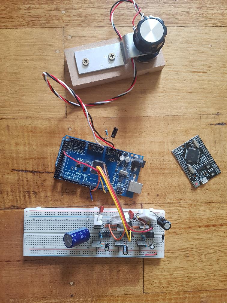 and the 3 half bridge MOSFET drives. I use IR2004 1/2 bridge drivers since I had them here already. Each 1/2 bridge has a low side MOSFET and a high side MOSFET. The high side FETs need the diode/cap charge pump. When running this with about 1.5 Amps at 25V into the AC servo motor the MOSFETS remain at room temperature. That is a sign of fast switching. 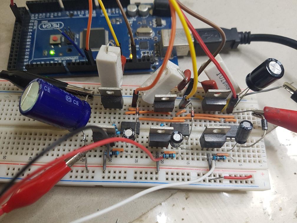 There are 3 x RC snubbers on the low side. They help a bit to reduce problems from doing this on a breadboard. Motor DC supply on the left. 12V IR2004 IC supply on the right. Edited 2020-12-25 16:59 by poida wronger than a phone book full of wrong phone numbers |
||||
| Warpspeed Guru Joined: 09/08/2007 Location: AustraliaPosts: 4406 |
Great stuff Peter. Cheers, ĀTony. |
||||
Revlac Guru Joined: 31/12/2016 Location: AustraliaPosts: 1277 |
Very nice work Peter, the servo motor runs very smooth. Is there any need to change the 20khz pwm, some of the VFD's can be adjusted but I thought it might have been to reduce any noise in the motor or something to do with toque, I will have to read the Manuel when I can find it. Another thought, I have seen electric car inverters around for sale, I don't have a clue if the control circuit and igbt modules are moulded together, there might be a possibility of driving one of those units, might not need a transformer, just high voltage solar input. The new Mega is much smaller than I expected, I'm going to have to me 1 of those to play with.  Cheers Aaron Off The Grid |
||||
| poida Guru Joined: 02/02/2017 Location: AustraliaPosts: 1476 |
I was thinking during the after dinner walk: maybe you could use something that did mppt on a solar array, put that power into a large capacitor or small SLA bank, then a 3 phase inverter to drive the pump. Only run the pump when enough solar power is present. I need a tame 3 phase fractional HP induction motor. Ebay? gumtree? There are two available at work but we reopen there on 12 Jan and I can't wait that long. wronger than a phone book full of wrong phone numbers |
||||
| Revlac Guru Joined: 31/12/2016 Location: AustraliaPosts: 1277 |
I had a similar idea a while back about hacking out the MPPT part of a GTI, I have a good 5Kw Xantrex, its a goer and I'm not sure I want to wreck it just Yet. The MPPT part of it is run by a card with a 10pin IDC and drivers onboard, It has some sort of ferite toriod or might be some other material, rather large for something like that. Well built. It just occurred to me that The MPPT unit might already RUN without any grid connected. Don't suppose I could get that lucky. I haven't seen many 3 phase motors under 1Hp, most places are closed ATM. Cheers Aaron Off The Grid |
||||
Haxby Guru Joined: 07/07/2008 Location: AustraliaPosts: 426 |
Your MPPT for your variable speed motor can be MECHANICAL! Just run the pump slowly if not much power available, and quickly if there is plenty. This concept works well for heat pumps and storage tanks, where instantaneous power doesn't really matter. |
||||
| poida Guru Joined: 02/02/2017 Location: AustraliaPosts: 1476 |
I think I get it, Haxby. the control loop would be increase RPM until solar array power drops past peak power. decrease RPM until array power increases to peak power. wronger than a phone book full of wrong phone numbers |
||||
| Haxby Guru Joined: 07/07/2008 Location: AustraliaPosts: 426 |
^ that's it. Some time ago I was thinking of a heat storage system based on this concept. The assumption was that heating and cooling were the biggest power hungry appliances in a home. Solution being a 5000L insulated tank that could be heated or cooled with a heat pump running directly from solar. No pesky batteries. Then at night, a small heat pump, with heat exchanger inside the 5000l tank could run a split system to recover the heat in a very efficient way. Or if enough delta T, just pump the water through radiators in the building. It could work for cooling too. |
||||
renewableMark Guru Joined: 09/12/2017 Location: AustraliaPosts: 1679 |
I have a small 3phase in the garage, I'll try and find it. Cheers Caveman Mark Off grid eastern Melb |
||||
| renewableMark Guru Joined: 09/12/2017 Location: AustraliaPosts: 1679 |
  Cheers Caveman Mark Off grid eastern Melb |
||||
| renewableMark Guru Joined: 09/12/2017 Location: AustraliaPosts: 1679 |
Bit like this https://www.thebackshed.com/forum/ViewTopic.php?FID=11&TID=11677 Cheers Caveman Mark Off grid eastern Melb |
||||
| poida Guru Joined: 02/02/2017 Location: AustraliaPosts: 1476 |
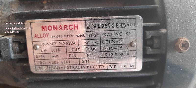
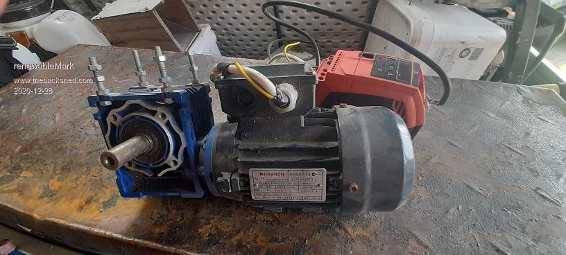
renewableMark: that motor seems ideal for testing. I Think I would like that motor very much. .. .. In other news I have spent a couple of hours calibrating the Tektronix A6902B Isolator. What is that? It gives you 2 channels of isolated inputs. Each input may be +/- 500V from ground. You can connect the ground lead clips to any voltage +/- 500V and see the voltage on the tip relative to their ground clip. (All CROs and DSOs have the ground leads connected to each other and this is connected to mains Neutral and Earth. Isolated inputs are a good thing with power electronics) That, plus the Pirtek DP-25 isolated differential probe will let me probe all 3 phases with any ground reference for any of the 3 phases. I plan to have individual AC output voltage control for all 3 phases. Not just one phase as the inverters we have built so far. So I need to measure all 3 phase's voltages, all referenced to the neutral, which will probably NOT be close to DC supply ground. Even if it was, I will want to assume it is not and be able to accommodate this. When I got the A6902B channel 2 was about 20% out in gain on channel 2. That is a lot. It was time to follow the Tek service manual instructions and calibrate it. Now I have this: 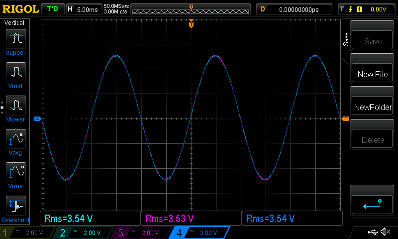 where Light Blue is the Pirtek, Purple and Dark Blue are the 2 channels of the A6902B Input signal is 10V p/p sine wave 50Hz. This is 3.53V AC RMS They all are very close. Undoubtedly the 3 phase inverter will have unbalanced loads and unbalanced outputs and I want to be able to see this to a few % or better. here they are with mains AC voltage: 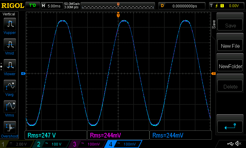 there is a bit of a difference now. I could have calibrated them with mains voltage as input but that is a dangerous thing for me to do. Calibration changed when I change from 2V/div to 100V/div. Oh well. They are now all close enough so that's that. Now, the transformer. I think I will make one using 3 toroids. I have 4 on hand, and they may not be all identical. With individual voltage feedback control for all 3, I think it will not matter much that the toroids are different. The feedback control will automatically handle any differences in output voltages for each phase. The prototype will only need to produce about 1kW per phase and probably less. This is 4 Amps at 240V per phase. So I intend to wire the primary in delta and the secondary in wye plus a neutral. I will need 3 240V->12V step down transformers for voltage feedback. I can use a single phase full bridge inverter which gives me 2 phases. And use another single phase full bridge inverter but only use 1/2 of it. There are a couple of spare boards here so that's sorted. What has to be built is the 3 phase controller board with 3x IR2148 drivers and charge pump bits, probably on perfboard. Time for a few days off in the bush chasing birds with my camera for now. See you all next week. wronger than a phone book full of wrong phone numbers |
||||
| Revlac Guru Joined: 31/12/2016 Location: AustraliaPosts: 1277 |
That little motor looks perfect for a test rig. I got hold of some Copper Prototype PCB Board should be big enough for this, used a few already for some other nano projects I remember checking the grid voltage when we had it here, there was 25vac difference between phases, I can see this way will be much better or perfect. Enjoy your trip in the bush, Every morning I open the door I get used as a bird perch, claws are sharp as. Cheers Aaron Off The Grid |
||||
| nickskethisniks Guru Joined: 17/10/2017 Location: BelgiumPosts: 477 |
Have fun Peter! This will be a fun project I will follow from close by :) You can use some isolation opamps like: acpl-c87, hcpl7800,... for measuring the phase voltage/ current. I once tried to make a simple 3 spwm with a CY8CKIT-059uC, I used 2 potmeters, 1 for the amplitude and one for the frequency, it was easier to program for me then the arduino. I could do it with internal hardware, comparing a sinewave with a triangle wave. But I think I ended up with using a lookup table. A colleague of mine did the same but programmed ōspace vectorö, that way you can extract more power from the same DC bus. We tested it on a small induction motor. It has some nice internal hardware you can set up without using uC power/clock cycles. It has free programming software with lots of help/information pdfÆs and basic examples. |
||||
| poida Guru Joined: 02/02/2017 Location: AustraliaPosts: 1476 |
Nicks: I had a look at the CY8CKIT-059uC and it's a very intriguing device. I love the built-in opamps and completely configurable hardware, that can be reconfigured on the fly during program execution. It's really nice. I will be staying with the Mega since I know that micro architecture well. Learning new micros might be easy for the young people but for me knowing the ATmega, Cortex M3 (Arduino Due), STM32F1 and STMF4 is enough. The above code is about 2/3 of the final code needed to run as an inverter. I have spent some time looking at the EG8030 documentation. It comes in two flavours, Chinese and Russian. Google translate is helpful. The EG8030 can run in a few different modes. The first 4 are (all have soft start same as EG8010): 3 phase with closed loop voltage control for each of the 3 phases, so that all 3 phases can be driven as needed to provide desired output voltage. 3 phase with closed loop voltage control taken from one phase or an external input with all 3 phases driven in unison to provide an output. The above but open loop. This is where the outputs are defined by the input in a 1 to 1 mapping. When loads are applied, voltages will drop. Other modes exist too. And interestingly, there is a digital input used to reset the SPWM to Zero degrees when triggered and this is used to synchronise multiple systems. I will probably go with the first mode. I want all 3 phases driven in a closed loop control, with each phase having it's own feedback voltage. The output frequency will be 50 Hz for start up and a few seconds afterwards, then reduce freq based in DC input power levels via a lookup table or something. There will be soft start from zero power to full voltage taking about 3 seconds. And a soft stop. I have ordered 6 x IR2148 gate drive ICs. Only need 3 so have a spare set for when things blow up. I need to collect a few bits - 3 x 12V transformers, chip sockets etc. And 3 good ferrite chokes, probably use the cheaper RS component ones. Here is the suggested circuit for the EG8030 You can see the 3 1/2 bridge drives and the delta/wye transformer. With 48V DC supply it suggests 20V AC primary winding which is a bit low to my mind. There are no primary chokes. There are 0.47uF caps across the outputs which does not seem right. I think we need correctly working LC filters with this but I can not see the inductance of the transformerand the 0.47uF caps helping much. 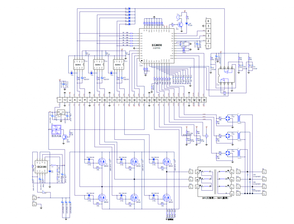 wronger than a phone book full of wrong phone numbers |
||||
| nickskethisniks Guru Joined: 17/10/2017 Location: BelgiumPosts: 477 |
Probably because they use delta to star. I think you can use star to star to use a higher primary voltage. Then you can use a 20 * 1.7 ~ 34V primary, I should think this over how things would work if there were a uneven load attached. |
||||
| poida Guru Joined: 02/02/2017 Location: AustraliaPosts: 1476 |
Simple VFD 3 phase motor drives use a control principle that keeps the Voltage and frequency ratio constant. Let's say the drive is set to output 240V AC at 50 Hz. This ratio is 4.8 The output voltage will need to be altered to maintain this ratio as the frequency changes resulting from the operator's input. eg. A freq of 25Hz means 1/2 the 240V or 120V. (120/25 = 4.8) Looking at some important facts of centrifugal water pumps from here gives flow rate is proportional to RPM head or output pressure proportional to RPM squared motor power is proportional to RPM cubed So for a doubling of RPM, the motor will need 8 times the power. And for 1/2 RPM, the motor now needs 1/8th. So RPM of the motor is a powerful controlling factor of the power flowing through the drive when driving a cf water pump. I am looking at the outline of the control scheme for the solar powered 3 phase water pump and it's time to flesh out a few things. The solar array would need to be wired to give something like 60V at maximum power point. The motor is 2 hp or 1500W. A power level for the motor when running at 25Hz is measured during system build. And the power level at 50 Hz is measured. The inverter will need DC supply voltage and current sensing. The primary winding peak to peak voltage should be about 80% of the 60V supply. 0.8 x 60 X 0.707 = 34V AC RMS primary for 240V AC RMS on the secondary output. IF motor not running: The firmware would periodically check if the array voltage is greater than some reasonable start value. IF greater, then soft start motor to 25Hz. Only if input DC power = correct already known power level FOR 25Hz will it keep running. Else it soft stops. IF motor running: periodically increase output frequency a small amount and check if DC input power increases as expected. IF the input power drops, reduce the frequency a small amount. Only permit frequency to reach 50Hz. Also, if frequency needs to drop below 25Hz due to insufficient DC input power, stop motor. The search for fastest RPM or frequency while keeping input power adequate is similar to MPPT tracking. And always modify output voltage in keeping with the required V/f ratio of 4.8. The 50Hz to 25Hz range gives 1500W to 188W operating range for input power. It gives a factor of 2 flow rate range. I presume the pump will be sized such that at 25Hz it can pump water up the rise of the bore hole easily. Recall the frequency squared dependence for head pressure. I think this will work fine without any need for a battery. The build: One and one half inverter power boards, 3 primary chokes, 3 toroids, 3 12V output Vfb transformers, a current sensor and the control board based on the Arduino Mega. Why is there a need for constant V/f ratio? My view is the motor is an inductor and so if a voltage is applied for long enough then the inductor will saturate. From our inductor testing we found L = V x s / I where L = inductance (Henries), s = time (seconds) and I = current (Amps) From the above it's easy to see the V x s part, and if the voltage and time stay at a constant ratio, we will have no problems with increasing current. (the inductance stays the same) I just verified this with the single phase inverter on the bench. I have a modified firmware which permits changing output frequency from 40 to 60Hz. The toroid starts to saturate at about 45Hz with my 240V output. Saturation increases as the frequency drops further. A change to the code to have output voltage drop as the frequency drops now prevents saturation. I maintain the voltage/frequency ratio as a constant over the 40 to 60 Hz. I suspect the induction motor behaves the same way wronger than a phone book full of wrong phone numbers |
||||
| Revlac Guru Joined: 31/12/2016 Location: AustraliaPosts: 1277 |
Just as an example, I have a 24DC bore pump its one of those screw types, helical rotor or something. First thing it will do when connected, is check there is high enough voltage from the solar panel, in this case there is the usual 60 cell 250w 34V or 37 VOC not sure last time I looked, (I put 5 panels on it and it still runs with a light cloudy day) it will rev up to its running speed and the input voltage will drop a bit. When the voltage gets low the pump will also slow down, but still plenty fast enough for it to pump the pressure and distance needed. If the voltage lowers anymore it will stop altogether then check the voltage and try again after a set time. However it will not try to start at all if the voltage is too low, even though the voltage was slightly higher than the voltage it would stop at. Can't check this ATM, no water here, all still dry as buggery. I think there are some off grid solar air conditioners that work this way. For the 3 phase induction pump motor, this is something I thought I might have to try, with a trimpot just to find the sweet spot where its no longer worthwhile for the pump to continue running, previously I just took a guess at 40hz for the frequency and the cutout voltage from the solar panels would have to be determined later or percentage of panel working voltage......Not sure about this yet. So it looks like using the transformers, we may be limited to a frequency range which should be plenty to play with. When I had the VFD running I was sure I had a 3 phase motor running at very low hz and the power consumption was very low, there was some videos of people running a drill press at very low rpm, I will have to check this next time when the Vfd is connected to 1HP motor. I would be interested to try this, one using the transformers (still have to see whats available there) and the other one could be without any transformer, just high voltage solar input, perhaps if the MPPT works. The 3 phase bore pump here, I'm sure its star configuration, other above ground pump motors, (direct couple or belt driven) can be either star or delta, usually not hard to change if needed. Most of these pumps are only running to transfer water into a tank or a turkeys nest so some variation in speed or shutdown due to cloud cover wouldn't mater. It all looks good, I will read it all a few more times later, when I get my brains back into gear. Cheers Aaron Off The Grid |
||||
| Warpspeed Guru Joined: 09/08/2007 Location: AustraliaPosts: 4406 |
Transformer should be o/k, because as with a three phase motor, the voltage is reduced as as the frequency decreases. Cheers, ĀTony. |
||||
| Page 1 of 5 |
|||||
| The Back Shed's forum code is written, and hosted, in Australia. | © JAQ Software 2026 |
