
|
|
Forum Index : Electronics : 3 phase inverter for AC induction and servo motors
| Author | Message | ||||
Revlac Guru Joined: 31/12/2016 Location: AustraliaPosts: 1153 |
I can get hold of some IRS2184 drivers and I might have some 100V fets somewhere, good to start with, also have some 80A 650V IGBT"s to do something more powerful. Some reasonable size Metallized Polyester Film Capacitor to help with the high frequency ripple on the bridge supply, along side the large electrolytic caps, Do we need as much capacitance for 3phase as we do for single? Or is it just good practice? Cheers Aaron Off The Grid |
||||
| poida Guru Joined: 02/02/2017 Location: AustraliaPosts: 1432 |
No idea about capacitor sizes at this stage. My view is 1 hp 3 phase = 3 phases of 1/3 HP going into the motor. a 1 HP single phase has one phase of 1 HP going into the motor. So possibly we will be dealing with lower current levels. Don't know. Testing will be educational. The prototype inverter will use 3 toriods all wound with different primary to secondary ratios. All "about" the same but they will be different. I want to have all 3 phases driven to output the same AC voltage so that means 3 trim factors for the 3 phases in the code. wronger than a phone book full of wrong phone numbers |
||||
| InPhase Senior Member Joined: 15/12/2020 Location: United StatesPosts: 178 |
The current will be 1/sqrt3 times the single phase current. Or very close to it. |
||||
| Revlac Guru Joined: 31/12/2016 Location: AustraliaPosts: 1153 |
Haven't found 3 transformers that are the same, Thought I had some but only found 2 of each small EE types. Plan B Found a half decent 3 Leg transformer that I could rewind for 3 phase, it has some wire on all ready but will be stripped down and redone properly, see if my winding skills are still up to the task.  Plan C There is a 3 phase welder in the shed, Repaired and repainted it years ago, might try that without the old man finding out.  Found some plug packs, will crack them open with a hammer and chisel, see if the voltage is all the same. Still more parts to find. Cheers Aaron Off The Grid |
||||
| BenandAmber Guru Joined: 16/02/2019 Location: United StatesPosts: 961 |
hay poida whats the chances of getting a nice screen to show every thing going on and wifi to see from phone also on your next control board i have not been reading and keeping up so i may sound a little silly like always i sent one of your control boards out to a friend hope you didnt mind i have a newer scope now also hantek dso5072p i was also wandering if two transformers could do 3 phase or do you have to have three be warned i am good parrot but Dumber than a box of rocks |
||||
| InPhase Senior Member Joined: 15/12/2020 Location: United StatesPosts: 178 |
Two transformers can be used for three phase in what's called an "open delta" configuration. You can only get 57.7% of the power that three transformers would give you though. |
||||
| Revlac Guru Joined: 31/12/2016 Location: AustraliaPosts: 1153 |
This is one candidate for a 3 phase transformer, its about 40kg as is without the winding on the center leg. It will need a complete strip down and rewind, will start a new topic and post further details later when I get to this stage. 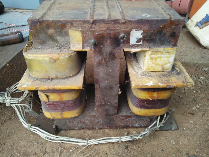 Cheers Aaron Off The Grid |
||||
| nickskethisniks Guru Joined: 17/10/2017 Location: BelgiumPosts: 462 |
Hi Peter, Did you make a version for a 3ph inverter? Thanks |
||||
| Warpspeed Guru Joined: 09/08/2007 Location: AustraliaPosts: 4406 |
For fractional Hp, don't overlook stepper motors and dc motors. Cheers, �Tony. |
||||
| Pete Locke Senior Member Joined: 26/06/2013 Location: New ZealandPosts: 182 |
Thanks for those links Tony. Very interesting reading. Cheers Pete'. ....Fekin' computer (possibly operator) Replied in the wrong post  . Please ignore... . Please ignore...Edited 2021-11-30 15:56 by Pete Locke |
||||
| poida Guru Joined: 02/02/2017 Location: AustraliaPosts: 1432 |
I don't make a version, as it were, but I can alter existing code to suit your needs. Firstly, the 3 phase code needs the Arduino Mega board, due to needing 3 x 16 bit timers. Next we need to choose the control scheme. Can we control output of all 3 phases by using the feedback from just one phase? Or do we want to control each of the 3 phases by using a feedback voltage derived from each phase? This is more of a design choice that has more meaning if you intend to run potentially unbalanced loads. The code will be quite simple either way. It will use 20kHz PWM, use PID closed loop control and have the soft start and soft stop function. I will get to the programming when you show you want to use it. It could be fun. The 3 phase transformer will be important. I always imagined 3 toroids, wired in a way that 3 wires go in and 4 wires come out, the 4th wire being a common or neutral. Having this common/neutral wire makes obtaining feedback voltage much easier. Just use 3 x 240V -> 12V small transformers, all with one lead going to neutral and the others going to each of the 3 phases. What's on your mind, eh? wronger than a phone book full of wrong phone numbers |
||||
| poida Guru Joined: 02/02/2017 Location: AustraliaPosts: 1432 |
a version I knocked together today: megaverter_3phase_pwm.zip Vfb for the 3 phases are on A0 to A2 gate drive output enable for the IR2184 is on D7 D8 is the inverter on/off signal. Hold it LOW for off, hold it HIGH for run. wronger than a phone book full of wrong phone numbers |
||||
| nickskethisniks Guru Joined: 17/10/2017 Location: BelgiumPosts: 462 |
Arduino mega or due is not an issue, I have used both in other projects and have enough spares laying around. I want to be able to use unbalanced loads, don't know if it's possible to load a 3ph transformer heavily unbalanced, but would like to test it. For now I want to limit it to 3 separate transformers, so unbalanced loads are no issue, so I can use a 3ph device. Even 3 different transformers should be no issue I guess. So 3 measurements are desirable, I do have a small 3ph transformer were I would like to experiment with, but I need to rewind it, or create a 3-400V source and use igbt's or similar. I will use a neutral "star" point. Thanks for helping me! Thanks for your time already, I will take a look. |
||||
| poida Guru Joined: 02/02/2017 Location: AustraliaPosts: 1432 |
After initial testing of the above code I found a few errors. I now get this: 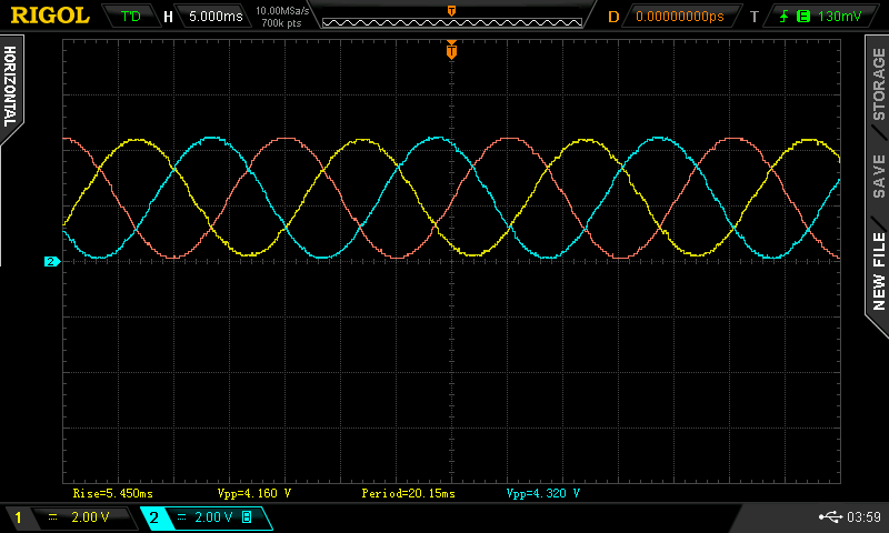 the output freq is 49.66 Hz this is smoothing the PWM to the low pass filtered average value within the DSO to show the nice sine waves. I trigger on the midpoint on the rise of the Orange trace which is coming out of pin D11. code is this megaverter_3phase_pwm.zip this shows Yellow - Blue which is what one of the windings of the 3 phase delta transformer would see. Notice it's bipolar, goes from -4V to +4V, at 50Hz This is what we want. 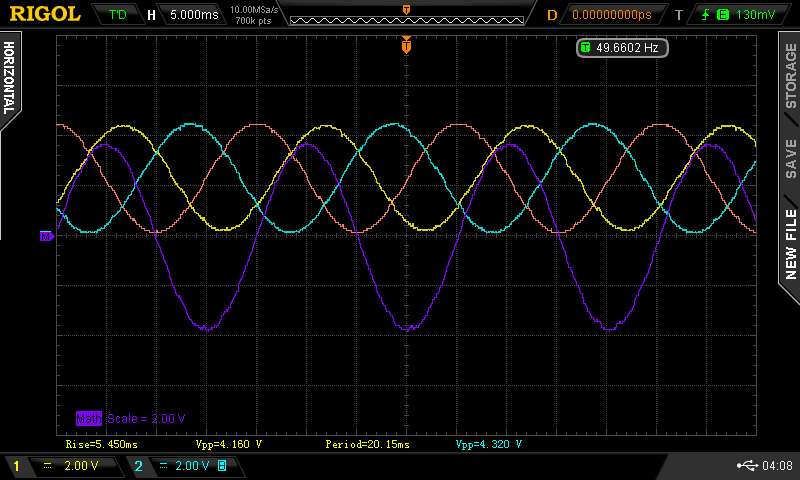 Edited 2021-12-02 08:24 by poida wronger than a phone book full of wrong phone numbers |
||||
| nickskethisniks Guru Joined: 17/10/2017 Location: BelgiumPosts: 462 |
Never had the chance to test your "faulty" software, but I finished enough hardware today and your latest code is working great! I did not test the voltage feedback yet, I will try that the next day. Can I change the ppwm to a higher divider or will it mess with the 50hz? I need to take some extra time to go thrue your code. I'm testing with big igbt's for easy testing but they are a bit slow. Thanks Peter. |
||||
| poida Guru Joined: 02/02/2017 Location: AustraliaPosts: 1432 |
Nicks, I'm not sure what you want to do. Would it be correct you want slower PWM, maybe only switch at 10kHz not 20kHz as it currently stands? wronger than a phone book full of wrong phone numbers |
||||
| nickskethisniks Guru Joined: 17/10/2017 Location: BelgiumPosts: 462 |
Actually I needed a bigger deadtime, I got a bit of cross conduction, and so shoot thrue events. Putting gate turn off diodes parallel with the gate resistors gave me faster turn off times. Only just enough, 300ns turn on, 700ns turn off, I think I need to make another driver board with the ir21844 to add some extra deadtime. Or just use some other igbt's/MOSFETs. Edited 2021-12-05 07:39 by nickskethisniks |
||||
| nickskethisniks Guru Joined: 17/10/2017 Location: BelgiumPosts: 462 |
Still working on the hardware and suitable loads to test with. Peter, I do have a question, one of the reasons I'm playing with a 3phase right now is the fun of exploring new possibilities :p. But also to add some extra power to my system. Last night I was dreaming about another option, where it might be possible to parallel 1phase inverters, did you wonder about that idea too? I don't know if it's possible to run for example 2 nanoverters in parallel, my idea was to run 2 uControllers from the same clock or interrupt, maybe 1 master that's providing a clock or interrupt to slave inverters. That way they should run synchronized, if each is measuring the total current and their own (DC input current) they could adjust their amplitude to try and share the current, if they know how many units there are in the system. Or just measure there own current and limit it to their nominal rating, current would not be equally shared. Any advice on this matter? Thanks. |
||||
| poida Guru Joined: 02/02/2017 Location: AustraliaPosts: 1432 |
More power: a few ways to go about it 1 - two or more inverters, running independent control loops and with differing output and phase. Place AC loads on each inverter to distribute load. 2 - make the too small inverter bigger via a larger toroid and upsized power board, DC supply wiring etc. 3 - two or more inverters, this time with the second inverter in strict phase alignment with the first. Both inverters run independent control loops Now we have AC output that is very tightly in phase. 4 - two or more inverters, with the second one having no control loop - it just takes gate drive directly from inverter number 1. Sometimes the AC output will be too high or too low from inverter # 2. Most AC loads can manage a relatively wide range of input voltage. The phase difference in approach #2 is about 15 uS and probably less. This is about 0.27 degrees phase difference (360 * 15uS / 20mS) I do not like the idea of paralleling the outputs because I think the closed loop control will be upset. Since each inverter has it's control loop, both outputs will track the setpoint well. In my home I go with #1. No problems All choices use a single DC supply Choice #3 might be good when trying to reduce power losses. You could enable and disable second and subsequent inverters as the need arises. I think main power losses are DC resistance in the primary winding, Rds(on) and DC resistance in the secondary. All of these are I2R so reducing current is a good thing to do. I imagine 2 inverters built to 5kW but running at 2.5kW would be more efficient than one inverter built to 5kW running at 5kW Edited 2021-12-06 07:55 by poida wronger than a phone book full of wrong phone numbers |
||||
| phil99 Guru Joined: 11/02/2018 Location: AustraliaPosts: 2593 |
I have no experience with paralleling the AC side of inverters but there should be some similarities with generators. Maintaining a 3 x 1 MW system was part of my job. The individual feedback systems for frequency and voltage can interfere with each other causing instability, requiring a master controller to continuously tweak the governor and voltage regulator settings. Sharing of the true power is done by adjusting the phase shift between the generators (via the governors), not the voltage. Adjusting the voltage regulators only changes the reactive power. Turning up the voltage on one turns it into a capacitor, forcing the other two to become inductors. So the master controller must monitor real and reactive components for all the generators and the buss to make the right adjustments. Isn't AC weird and wonderful? |
||||
| The Back Shed's forum code is written, and hosted, in Australia. | © JAQ Software 2025 |
