
|
|
Forum Index : Electronics : Mad power board
| Author | Message | ||||
mason Regular Member Joined: 07/11/2015 Location: CanadaPosts: 86 |
Hi all, I keep blowing fets on the primary side of power board, everything checks out good but when I turn the nano on the fets start popping on one side, could it be bad 21844s ? Any help would be great. Thanks |
||||
| oreo Senior Member Joined: 11/12/2020 Location: CanadaPosts: 133 |
I presume you don't have a oscilloscope to look at the waveforms on the gates without the power fets installed? It certainly could be a bad 21844. Where are located in Canada? Greg |
||||
| mason Regular Member Joined: 07/11/2015 Location: CanadaPosts: 86 |
Hi Oreo, Yes from Canada , I'll put the scope on it and see what's going on, all the parts are Chinese so it could be anything. Thanks |
||||
Haxby Guru Joined: 07/07/2008 Location: AustraliaPosts: 426 |
Take a good look at the on/off time of the gates. I have had 2 MOSFET driver ICs fail in a sneaky way where they were mostly working but not turning off quickly enough. See pics towards bottom of page here |
||||
| poida Guru Joined: 02/02/2017 Location: AustraliaPosts: 1480 |
I think so How to check for correct IR21844 operation: All measurements are with respect to DC ground on the nanoverter. Disconnect the 10 pin ribbon cable. No need to blow more FETS. Power nanoverter board so that 15V is on the DC-DC converter output. I use a bench supply and connect to dc-dc outputs. No need for 50V battery etc. have nanoverter on "off" state. Pin 1 is PWM in. put DSO probe on that. You should see 5V very short pulses, at 20 kHz. While DSO probe on pin 1, start nanoverter. The run LED should light up. You will also see the increasing PWM width as the soft start is run. After a few seconds, the PWM width will be nearly 99% and stable. Verify this for both IR21844 pin 1 inputs. In turn, check the gate drive outputs for both ICs. with nanoverter "off", check no output on pin6, low side output. This must be zero when inverter is off. Then start inverter, you must now see an output, inverted compared to pin 1. This output needs to be 15V, the same as the IR21844 supply voltage. This proves 2 things. - the shutdown pin works as intended - the low side output drive works Do this for both chips. Next, ensure the powerboard DC cupply caps are discharged. Then connect the ribbon cable. Now we check the highside output. (we need the power board to be connected to give a "ground" for the charge pump to function.) Again, with inverter off, check for zero output on pin 12 (high side output) start inverter, and now note PWM output on pin 12. Again it needs to be 15V. This time it is a mirror of pin 1. Not inverted. This proves a few things: - high side output works - charge pump works - again, that shutdown pin works During these tests, look for poorly shaped squarewaves. I have seen poor shapes such as a 1/2 high start and a curve up to full voltage as the "squarewave" when testing damaged gate drive ICs. You will need a nice, fast squarewave. It will be likely you will have huge over and undershoot on these signals. This is normal and due to poor DSO probe technique. I have blown up gate drive ICs about 4 times when playing with the test nanoverter and each time I do the above before I even think about damage to the power board. Once you have proven the nanoverter is working properly, then look at dead FETS, dead totem pole transistors, dead charge pump diodes on the power board etc. Purple is PWM IN, pin 1 Light Blue is low side output, pin 6 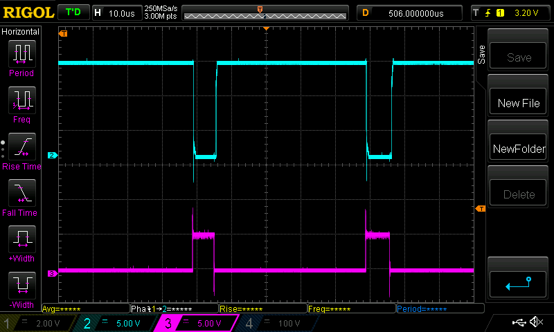 and now Light Blue is high side output, pin 12 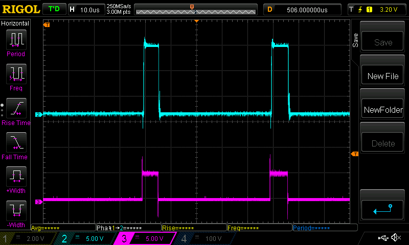 The 5V pulse is converted to about 15V on both outputs. wronger than a phone book full of wrong phone numbers |
||||
| mason Regular Member Joined: 07/11/2015 Location: CanadaPosts: 86 |
Thanks Haxby, I'll check that too. Thanks Poida for the detailed how to, appreciate that, pin 6 doesn't have the 15v you mentioned but pin one seems to be working. |
||||
| The Back Shed's forum code is written, and hosted, in Australia. | © JAQ Software 2026 |
