
|
|
Forum Index : Electronics : Power Jack LF + 3kw Aerostar inverter ??kw @ 48v
| Page 1 of 3 |
|||||
| Author | Message | ||||
| MasterCATZ Regular Member Joined: 25/03/2011 Location: AustraliaPosts: 52 |
Because I have a living room full of dead MPP HF Inverters I am wanting to build my own LF off grid inverter that can actually handle incandescent loads (fish tank heaters) I have 2x donor 3kw Aerostar inverters should I use 1 core or stack both cores and make a beast ? I figure building a beasty core would be better than having a spare backup inverter as mainboard is a cheap quick replacement unsure which inverter power board to buy I can not find a 15,000 kit that seemed complete https://www.powerjackpowerinverter.com/index.php?_route_=repair-parts-for-LF-power-inverter ~2018 EG8010 boards were all the rage , what is the best pick now ? does anyone have any current links to current production boards ? $185 https://www.alibaba.com/product-detail/48V-10000VA-Pure-Sine-Wave-Inverter_62497272745.html $239 https://www.aliexpress.com/item/33035311978.html my understanding is winds should be 8:1 ratio doing 48v / 240v I should be using .7071duty cycle 33v ~ 340v range 2800mmsq of steel is about 1 turn/volt and higher the turns the better the idle efficiency? (so larger the more efficient?) and double stacking would increase the cooling and increase the mm2 so each turn will be a lower voltage? but still need room to fit all the extra turns any online calculators out their to work out what size wire will fit ? or how much center core to remove to make wires fit ? what is the best way to join wires when turning? I know primary wires can be paralleled what about secondary? what calculator do people use to work out their cable thickness's I keep getting mixed answers I would like to be able to run 400 AMPS ~20kw I thought this would be 90mm2 ? as 20mm2 normally does 125amps ? Edited 2021-05-07 23:23 by MasterCATZ |
||||
| nickskethisniks Guru Joined: 17/10/2017 Location: BelgiumPosts: 481 |
Hi, let's start with the output you want, how do we need to see the 20kW? Like continuous power or surge/peak power? I would say we mostly use 3-4A/mm2 for winding our transformers, but we still use temperature measurements to make a fan come on as we don't want to run things to hot. It also depends a bit which grade of enamelled wire you use, materials, epoxy,... |
||||
| Warpspeed Guru Joined: 09/08/2007 Location: AustraliaPosts: 4406 |
Yes, for 48v lead acid battery. https://www.daycounter.com/Calculators/Max-Flux-Density-Calculator.phtml No, for one turn per volt you need 4800mm sq of steel. Use the calculator, aim for flux density of 10,000 gauss. For example: 240v .00005 Mhz (four zeroes) 240 turns 48cm square steel result = 10,010 gauss Yes, but it reduces full load efficiency and maximum power because to fit more turns on requires the use of thinner wire. But its a good tradeoff. Larger means bigger hole, fewer turns required and thicker wire is possible. Double stacking means only half the number of turns are required to reach the magic 10,000 gauss. So wire twice as thick will fit the same sized hole. That means twice the current is possible = twice the power rating. No you need to work it out yourself, because how much wire will fit depends on the thickness of insulation, and how carefully it is wound. Just stip, solder and insulate, placing the join on the outside circumference. No problem. Calculate the cross sectional area in square mm of copper. Current density recommended is 4 amps per mm square. Ninety mm sq cable = 360 amps continuous. Cheers, �Tony. |
||||
| MasterCATZ Regular Member Joined: 25/03/2011 Location: AustraliaPosts: 52 |
Thanks Warpspeed and you just solved what I was trying to work out the last 4 hrs ( Current density recommended is 4 amps per mm square. Ninety mm sq cable = 360 amps continuous I will use 3 Amps as you said 3/4 ) I pretty much want to build the core as beastly as I can do not have time to make it a second time is their such a way to run coils in parallel , if so any benefits compared to stacking ? I am planning on running fish heaters / A/C 1 set of heaters is 5kw the second set of emergency heaters is another 5kw so it will need to do 10kw constantly during winter and I like running 50% duty for safety head room efficiency is not too much of a concern currently 10kw of surplus solar power going to waste (no export and the heaters are controlled based on battery bank voltage and weather forecasts ) should I unravel the core to change its internal / external sizes ? what is the minimum and maximum distance between the Primary coils (where the void is in the center assuming it is just left vacant for mounting bolt?) what I currently came up with was 3x 50mm2 cables for Primary (8mm) ~450AMP I will readjust my CAD to work it out for 10,000 gauss (Visual aid for seeing if wires will fit ) Bmax(DC)= (L*Idc*108)/(NAc) what is L ? not having much luck getting matching answers using that webpage with your numbers 240Vrms 0.0005 mhz 240turns 4.8cm2 9384.38 gauss ? and my CAD spreadsheets doing 10,135.14 gauss if it was 9.1cm2 would you do 128 turns ? or 118 ? just trying to work out where the variance is coming from my guess CAD is rounding up somewhere yep cad rounding damn their goes that idea (4.44*F*N*Ac) = 2.585856 not 2.59 Edited 2021-05-08 11:47 by MasterCATZ |
||||
| rogerdw Guru Joined: 22/10/2019 Location: AustraliaPosts: 955 |
Howdy MasterCATZ, sounds like a pretty gutsy machine needed. Good luck with it.  Not sure if you had a typo in your reply or you missed the detail ... but it is .00005 Mhz (four zeroes). Cheers, Roger |
||||
| MasterCATZ Regular Member Joined: 25/03/2011 Location: AustraliaPosts: 52 |
well their was that as well but did not affect the formula I just had to change to 91cm2 so the above question would be if you had 91cm2 how many turns would you do ? I am leaning towards 128 as most seem to work it out from 260v ironically that is the number my rounded up cad gave me working with 240v but working it out with 10,000 guass the turns seem higher ? OzInverter with the 91cm2 did 80 Turns saying each turn was 3.25V? back to being unsure who's maths to use? Solder Seal Wire Connector Marine Grade Heat Shrink Wire would these be usable for joining wire in a transformer ? if anyone knows how to stop freecad rounding I am all ears 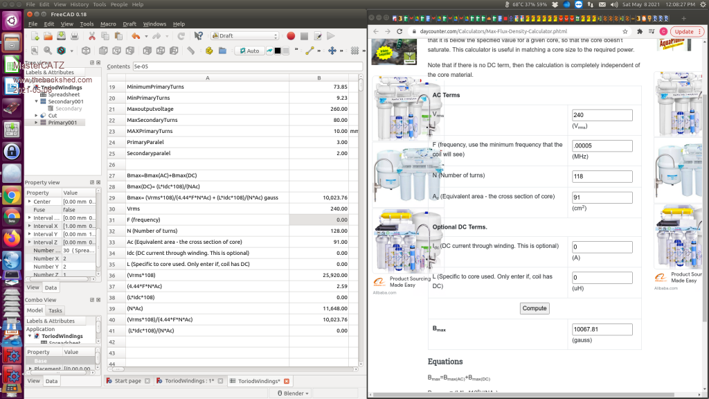 google spreadsheet seemed to be closer still not a match 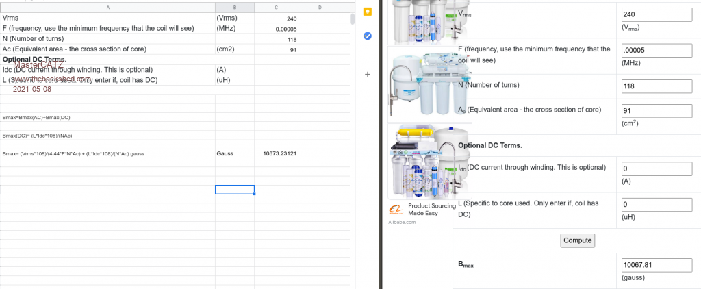 Edited 2021-05-08 12:48 by MasterCATZ |
||||
| Warpspeed Guru Joined: 09/08/2007 Location: AustraliaPosts: 4406 |
Don't sweat too much about exact precise numbers for any of this. You need some kind of target to aim for initially, and you don't need to hit an exact bullseye for everything. The main thing is to use numbers that are realistic and come up with some kind of trial paper design that looks like its all possible to build. If the numbers don't work out you can perhaps fudge a few things a little bit. Start with the core (or stacked cores). Work out the required turns for 10,000 gauss. Primary and secondary should each use up equal cross sectional areas of the hole. Work out what wire sizes will fit into the required space, allowing for enough turns and enough insulation, and allow a fair bit extra. The wire sizes that you end up selecting set the continuous final power rating. Short term surge power rating can be multiples of that. Just be aware that a 5Kw PWM inverter is pretty straightforward if you follow a proven design exactly. Its been done many times before successfully. A ten Kw design is vastly more difficult, and anticipate a LOT of problems to sort out. Its for the very brave and experienced only. By the time you get it going you will be very experienced, but it may take a long time to achieve that. A twenty Kw PWM inverter as far as I know has never been attempted by anyone on this or any other Forum. I would never myself attempt such a project myself, and as a professional engineer I have been designing these things for decades. These things scale up in power very badly, so be beware. Cheers, �Tony. |
||||
| MasterCATZ Regular Member Joined: 25/03/2011 Location: AustraliaPosts: 52 |
Thanks for the feedback Tony I did buy the OzInverter v2 + 3 PCB's as a starting point but so far no replies since payment unsure if I should stack cores and see what happens or just use a singe core and see if it does 6kw continuous and making 2x units nothing wrong with me using a inverter per AC / Circuit what is the math to find the amp / watt limits of a toroidal transformer based on kg / mm2 ? , it will be running in a hot shed using the example I found of their OzInverter online (assuming v1) it said "4off /4 in hand, 1.8mm diameter at 118 turns Secondary, and 50mm/2, 14 turns, Primary" I am assuming that is 4x parallel Secondary 2.5mm2 = 10mm2 per wind = 1180mm2 ? and I think that means they used 50mm2 14 turns for 700mm2? or is it 2x parallel for 1400mm2 ? 7.98mm dia ? and would perfect world wire matching be 1180mm2 Primary / Secondary ? or is the equal cross sectional areas of the hole including the voids ? ie) 91.8mm diameter (external of secondary wire ) - 90mm diameter (internal of hole )= 6 618.74 - 6 361.73 = 257.01mm2 and now I am wondering why that is smaller mm2 then 1180mm2 when I was working of each wires mm2 *edit* oh I see they would have to overlap only ~150 wires fit arround the core 97.2mm diameter (external of 4th secondary wire ) - 90mm diameter (internal of hole )= 7 420.32 - 6 361.73 = 1058.59 hmm still a bit off 99.78 diameter (external of Primary wire ) - 91.8mm diameter (external of secondary wire ) = 7 819.46 - 6 618.74 = 1200.72 mm2 ? sorry for the question I want to get started but I think it will be built before the book ever arrives ... especially with covid around the other thing will be to sort out chokes , binding it tight seems to be the goal how do you determine how many turns / wire thickness same as Primary? and the final would be AC filter Edited 2021-05-08 17:43 by MasterCATZ |
||||
| rogerdw Guru Joined: 22/10/2019 Location: AustraliaPosts: 955 |
I've been meaning to mention this calculator for winding toroids for some time .. Toroid Winding Calculator Just bear in mind that where the calculator asks for wire RADIUS ... put in DIAMETER ... otherwise you may get a surprise when you go to wind it. I did email them and let them know ... but had no response. If I input the actual wire DIAMETER instead of the RADIUS ... the calculator is correct with number of turns and also very close to the actual length of wire I used as well. My crude method for working out the likely number of turns that will fit in just one layer is to reduce the diameter of the hole by the diameter of the wire ... ... work out the circumference of that circle ... then divide by the diameter of the wire. In my experience that has worked out well enough for me to predict the result very accurately. Cheers, Roger |
||||
| rogerdw Guru Joined: 22/10/2019 Location: AustraliaPosts: 955 |
MasterCATZ, seeing you want such a high output, have you considered building a Warpinverter instead of an Ozinverter. Warpspeed won't suggest it to you ... he's too humble. I don't know how much you know about them but they require 4 toroids per inverter ... but if you can build just one inverter instead of two, it's not going to be that much more work. Tony, you mentioned that 5kW for an Ozinverter is fairly common ... but to expect difficulties if trying to go for 10kW. What sort of limits do you think a Warpinverter would have in a homebuilt scenario. I believe it would scale up much easier than an Ozinverter but I'd be interested in your view. Cheers, Roger |
||||
| Warpspeed Guru Joined: 09/08/2007 Location: AustraliaPosts: 4406 |
That would be the best way. If you have a 5Kw air conditioner, build an inverter just for that alone. If you have a 5Kw fish tank heater why not use a heating element that runs directly at 48 volts ? Its just over 100 amps, it would be far more efficient and reliable than an inverter anyway. Warpverter scales up much more easily, and there is really no practical upper limit to power. But at 20 Kw I would be thinking of running it from at least 200v dc. That is still 100+ amps but its a lot more practical than 400+ amps at 48v. Cheers, �Tony. |
||||
| MasterCATZ Regular Member Joined: 25/03/2011 Location: AustraliaPosts: 52 |
if the Warpinverter is what I think it was , it required custom PCB work ? I will only have 2x matching cores not 4x tho if I bought the remaining 2x working inverters they had instock for $700 I would have 4x matching cores I do not mind having 2x separate units for redundancy and the PCB is only ~$100 to replace vs a HF transformerless inverter well which method will be best ? I only want to build once :P I have tried finding fish safe DC heaters and could not really find them 240v 500w stainless steel heaters are only $10 ea as well and because just about everything is plastic I did not want super hot inductors near them plus the battery bank is 100m away ... and the fish tanks span 20m sticking with AC seemed the easiest option and I worked out the "Primary and secondary should each use up equal cross sectional areas of the hole" 1:8 ratio  Primary 1 / 8 Secondary Primary 1 / 8 Secondary 345 Amp 50mm2 = 6.25 mm2 wire , so I either buy 6-7mm2 wire to do the turns or reuse the 1.8mm wire = 3 - 4 winds , I noticed everyone is insulating between every secondary layer ? I thought that being parallel it would not matter ? Mylar Tape ? kapton ? or epoxy or ??? I was going to use this but its only 5kw and low temp Name: PET Insulation Adhesive Mylar Tape Length: 66 meters Substrate: polyester film Thickness 0.055mm Length: 66m Temperature resistance: 130 Elongation: 100% Peel strength: 250N/M Breakdown voltage: 5.5KV Electro-erosion coefficient: 1.0 Flame retardant rating: 94V-0 Excellent solvent resistance currently also deciding between 50mm2 and 70mm2 not much price difference any reason to not use flexible welding wire ? would this have too much vibration ? doing 70mm2 I could do 5x layers of 1.8mm mind you the more I look at this I feel I will be altering the core size ... I do also do have a few rolls of 100m 6mm2 wire here , whats best multiple smaller strands and trying to line layers up or just using 1 wire ? I am also wanting to run this on only fully charged batteries to use up all the excess solar power so maybe I should do the primary for a higher voltage ? I do not plan on running it below 52V I normally keep batteries always above 50v the only inverters allowed to use power under 50V are the airpumps would 1:7 Ratio be better for me ? oh and another thing I run super caps with my battery bank I read the Gauss range is 10000 ~ 20000 lower the number the more winds = more efficienty ? thanks heaps Edited 2021-05-08 22:07 by MasterCATZ |
||||
| Clockmanfr Guru Joined: 23/10/2015 Location: FrancePosts: 437 |
OzInverterNo2BookToroidC.pdf Hi MasterCATZ, Please find attached PDF on the tech stuff pages regards the torroid with the OzInverter. There are another 9 pages to the making the toroid Chapter. Please note OzInverter book edition 1, was based around the toroid for the 6-15kW Powerjack boards and they required 30 to 32v for the processors. For the 2nd Edition OzInverter book we have our own PCB's with the 8010 PWM SMD chip and this requires a voltage of 28 to 30v for a nominal 48v system. For the biggest OzInverter i have done, i call it rated at 8kW the toroid bare core works out at about 38kg, 230mm OD, 100mm center hole and the core 140mm thick/high, then 80 turns secondary at 6off, 1.8mm diameter and just 10 turns of 1off 75mm/2 for the primary. NOTE, at this weight of toroid the windings are being crushed, so good even winding and good mounting is very important. TESTING ...... Big OzInverter toroid test, just using a 2.5mm2 test primary wire. ....... 234vac going in the secondary's 80 turns, after the step up light bulb process .... and 29.4vac reading on the Primary. So our initial winding calculations are correct. Remember if in doubt a few more secondary windings will not hurt. See test procedure later in Chapter. The two photographs below, show the 8kW BigOzInverter toroid under testing, but here it has a temporary primary cable/wire. The 8kW BigOzInverter has a secondary of 80 turns and a primary of 10 turns. Remember we want the primary to read between 28vac and 30vac, and the below photo shows 29.4vac, that's good. 1st pic shows 234vac going in. 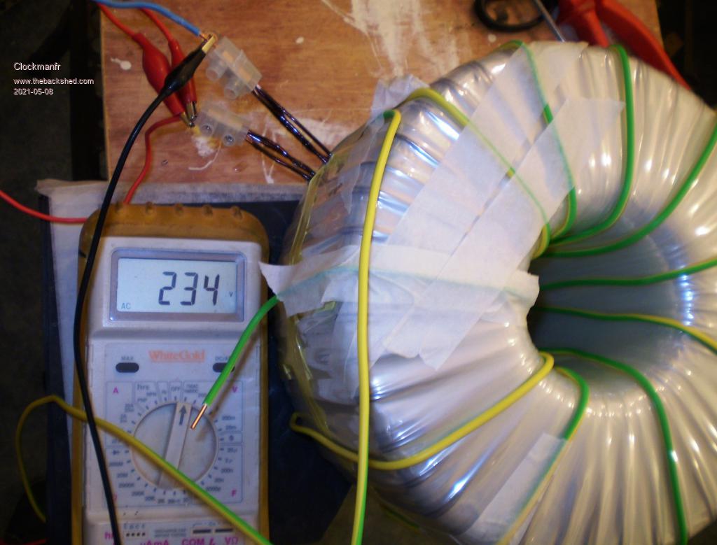 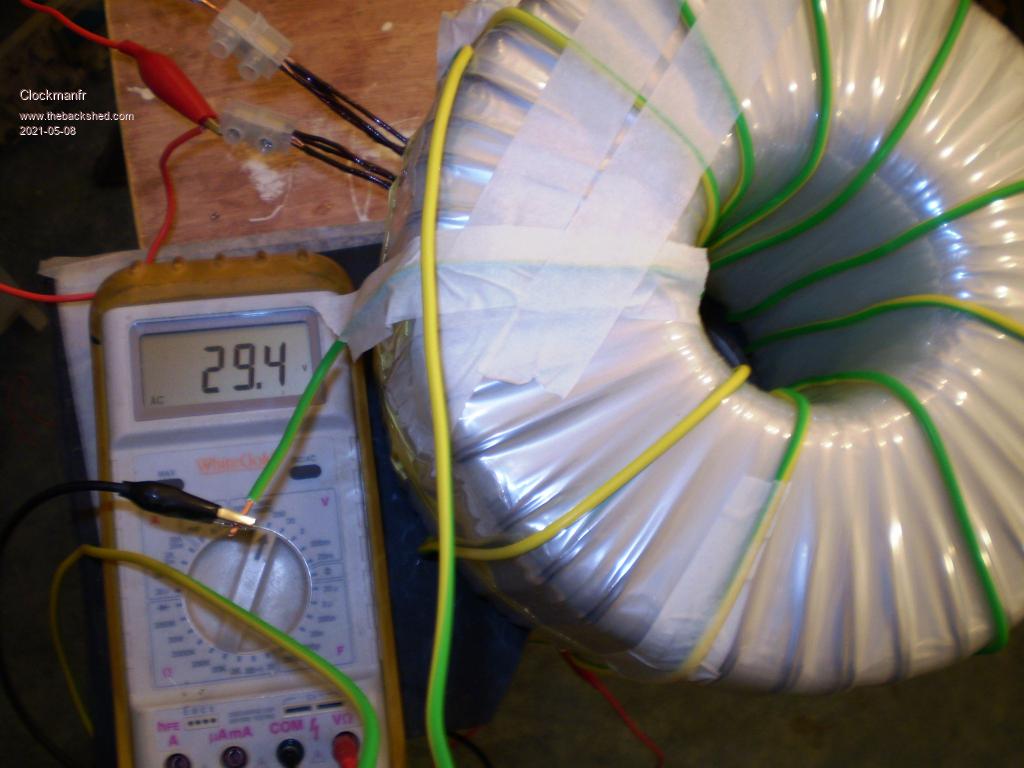 I trust this helps explain, but all the details are fully explained in the 2nd Edition. Edited 2021-05-08 21:39 by Clockmanfr Everything is possible, just give me time. 3 HughP's 3.7m Wind T's (14 years). 5kW PV on 3 Trackers, (10 yrs). 21kW PV AC coupled SH GTI's. OzInverter created Grid. 1300ah 48v. |
||||
| Clockmanfr Guru Joined: 23/10/2015 Location: FrancePosts: 437 |
Here is the 8kW OzInverter toroid assembled. Thats a 52kg lump. 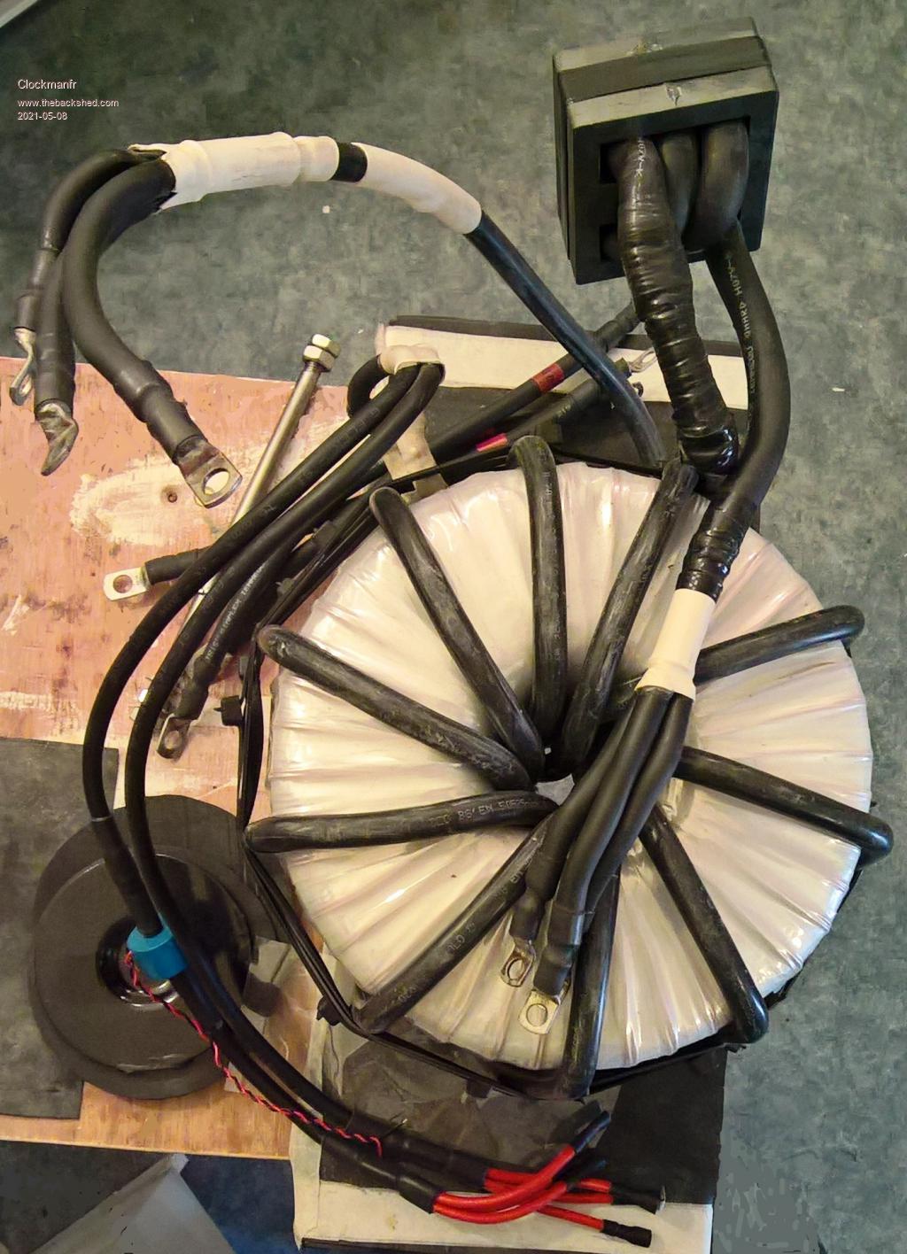 Everything is possible, just give me time. 3 HughP's 3.7m Wind T's (14 years). 5kW PV on 3 Trackers, (10 yrs). 21kW PV AC coupled SH GTI's. OzInverter created Grid. 1300ah 48v. |
||||
| MasterCATZ Regular Member Joined: 25/03/2011 Location: AustraliaPosts: 52 |
@Clockmanfr thanks , so with the board I ordered from Leslie Bryan I still have to stick with 1:8 ratio for the 30V for it to work anyhow ? anyway to mod it to run slightly higher nominal range to do 1:7 ratio? it will always be running from float voltage with 800+ amps coming in from the solar chargers I was also wondering why the 50mm2 cable any harm in running smaller parallel cables side by side to spread it out a bit more ? Edited 2021-05-08 22:18 by MasterCATZ |
||||
| Warpspeed Guru Joined: 09/08/2007 Location: AustraliaPosts: 4406 |
235v rms divided by 7 = 33.57 volts rms or 47.46 volts peak. You can plan on losing two to three volts across all the wires, mosfets, choke, primary and secondary transformer resistances at full load. So below about 50v right at the inverter input, the output voltage is going to drop out of voltage regulation. You will only be able to ever use a small fraction of the total battery capacity. Why would you want to do that ? Cheers, �Tony. |
||||
| Clockmanfr Guru Joined: 23/10/2015 Location: FrancePosts: 437 |
Okay, with those of you with an enquiring mind, here is what is happening in the real world, from real working experinces, ie, empirical evedence. 'Oztules' explains. "The 8:1 ratio thing is a product of head room and the properties of a sine wave. Our 240vAC is really 340v with .7071duty cycle... to get our 240v rms ac. So to make 240v AC from a DC source we need to handle the 340v part of the curve as well...... so our DC side needs to be .7071 of the expected AC wave generated in it or for 48v about 48X.7=33v.... so we need at least as low as a 33v primary to get to the peaks needed to make the sine wave....... now with losses in the switch, wiring, sags to cover high power surges etc, we need another 15% safety margin so we are reasonably assured of getting our 240vrms at all times. So now we can see why we are using about 8:1 for our transformer. We are really winding a 48Vdc primary (30 odd volts AC rms sort of thing) to make 340v peak ac or 240v AC rms. ( the rms is the root mean square... which is equivalent to the DC heating value..... so the power in 340v peak ac sine is equal to 240vDC in raw heating power ( no power factor)... or 240vac as we call it for the mains. If you rectify and filter... you will measure 340vdc." "Transformers are only as good as their cooling. That's what defines their power rating really. The little Chinese PowerJack toroid transformers in their own manufactured Inverters can do very impressive start ups, and short runs at very high power, but not for long. They will do the output they claim... but not for long. They limit the big figures to about 12 seconds ( so it does not vaporise), peak for much less, and if you read the figures on the unit itself regarding what you can run, it is quite realistic... but way less than the headline figures. The size of the transformer is a fair indication of it's power handling. I found 2800mmsq of steel is about 1 turn/volt ( from memory). We only use bigger steel because we need bigger wire to keep the copper losses down... so we need to be physically bigger. A big core can also help with cooling, and evens out the transient temps as a heat bank. The core size is not really a case of power: size..... if we had copper of zero ohms per foot of whatever size we had in our hand... then very high power transformers could be had very very small. The magnetising current is fixed for freq and voltage for a core..... you cannot saturate it unless you change the hertz or the voltage.... so core size does not dictate power handling.... sounds wrong I know So what does? It is the copper loss that causes us to use bigger cores... we need the real estate to use 3X 1.8mm wire and 90mmsq wire of the turns needed to do the job. The bigger the core, the less turns you need for the same frequency and voltage.... so for the same winding window we get more copper in there... we can make a bigger window and get more copper in there.... and we can see where this is going.... to get more and bigger wire in there, we need to use more core to get more real estate to play with... and better still .... less turns of it too.... so bigger wins. If we had super conductor wire, then this would be mute. We could use any core for any voltage and freq ( 50-60hz etc), as the wire could be thinner than hair, and carry a 1000 amps, so we could have our 2000 turns on a tiny core, and handle huge power.... remember saturation is not from current or over loading... so once the core is magnetised for that voltage and frequency, all extra amp turns involved with the transforming process do not direct their extra amp turns into saturating the core, but rather using their MMF against each other, and inducing current into the other...but not the core... so if you look at the equations for core saturation.... no mention of current... anywhere. The little Chinese PJ toroids do the job, but their copper loss heats them up too fast to be useful for more than a kw or two, and their sag will be pronounced... so we use a bigger core to allow us to use sensible sized wire to keep the copper loss to a value we can handle heat wise. Where does this get me???? well core size helps us get to our objective heat wise. If we used silver wire, our core could be smaller, as the R is less for the same power handling.... and losses are I^2R... we need R to be tiny for high currents.... or we burn up. A big core handles no more power... but allows us to use much more copper to get the losses under control..... then the transformer as a whole handles more power for longer, or if we have enough cooling.... indefinitely.... ie oil cooled, forced air cooled etc. I guess what I am trying to say is that core size is an indicator, but the copper is where the bulk of loss comes from, particularly in toroids, hysteresis loss is generally small for size, and eddy currents are small, as they use very thin laminate compared to EI ones. They tend to use high grade steel for toroids, as they are very expensive to wind to start with." 'Oztules' I find this a good explanation of the 8 to 1 ratio in a practical sense. Everything is possible, just give me time. 3 HughP's 3.7m Wind T's (14 years). 5kW PV on 3 Trackers, (10 yrs). 21kW PV AC coupled SH GTI's. OzInverter created Grid. 1300ah 48v. |
||||
| Clockmanfr Guru Joined: 23/10/2015 Location: FrancePosts: 437 |
Oztules once said to me, "Just listen to what 'Warpspeed' has to say, as he actually knows what he is talking about". Yes, multiples strands of copper cable can be used instead of just one 50mm/2 cable. But if you look inside the 50mm/2 cable it has about 18 strands of large copper wires twisted together and sheathed with a good insulator. I just prefer a single cable when winding. Biggest i can manage is about 75mm/2 and that's after many toroid windings. Multistrand fine cables can be had at 50mm/2 and 75mm/2 and these are very flexible as they have very small copper cables inside, the only drawback is that they can make noise internally as they rub/vibrate on themselves. I only use fine strand cables on the PCB connection breakouts and the Choke, although things have moved forward a bit with chokes. Everything is possible, just give me time. 3 HughP's 3.7m Wind T's (14 years). 5kW PV on 3 Trackers, (10 yrs). 21kW PV AC coupled SH GTI's. OzInverter created Grid. 1300ah 48v. |
||||
| MasterCATZ Regular Member Joined: 25/03/2011 Location: AustraliaPosts: 52 |
with the 1:7 mostly to make sure it will only run on full batteries as I am using the inverter to dump the excess power being generated how ever I was told we have to manually start these so that may not work how I wanted anyhow, as I was just wanting something that would automatically output when ever their was excess power as this will only be connected to heaters my thinking of using smaller primary cable was to allow the cables to fill in the voids around the hole better how ever yesterday I forgotten to add the sheath into the CAD so it looked like their was more space then their actually was with the flexable welding cable being used as primary any other concerns other than the sound ? these strands would not degrade over time from vibration? its running in the pump / compressor shed noise is of no concern I was also planning on removing the external sheath I was also thinking about 3D printing a winding template for spacing so each layer was directly ontop of the previous layer any issues with this ? I was planing on winding wire over it and leaving it their for each layer or is it best for only the wire going down the hole to be aligned and have the external turns spreading out filling in the gaps ? it looks like with the 70cm2 cross section of using 1 core if I was wanting to use 70mm2 primary cable I would need the core to be 220mm external 120mm internal 4 secondary layers 2.5mm2 of 166 turns 20 Primary Turns ? does that seem about right to you , any benefit in doing this as a single core project? I figured having more turns might help the core ? 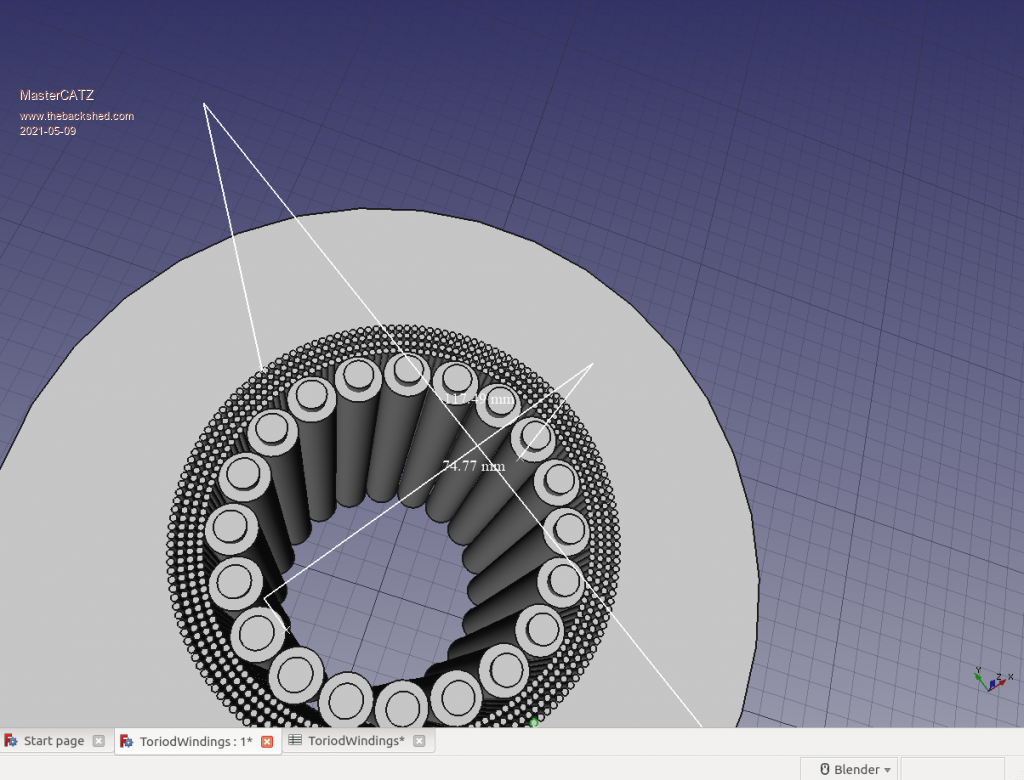 Edited 2021-05-09 11:45 by MasterCATZ |
||||
Haxby Guru Joined: 07/07/2008 Location: AustraliaPosts: 426 |
Can you post a pic of the transformer nameplates? Since you are burning off excess solar, transformer idle power won't be an issue for you. If you are lucky, You might be able to modify the transformers you have without much work. |
||||
| Page 1 of 3 |
|||||
| The Back Shed's forum code is written, and hosted, in Australia. | © JAQ Software 2026 |
