
|
|
Forum Index : Electronics : MOSFETS and Motors
| Author | Message | ||||
| InPhase Senior Member Joined: 15/12/2020 Location: United StatesPosts: 178 |
I am finally firing up my nanoverter after a lot of prototyping. It is to the point of being able to handle serious amps. I've only gotten it up to a little over 1 kW so far. I have made a modular design where I can add FETs as needed. My test loads have been incandescent lamps, space heaters, and brushed motors. I wanted to try an induction motor so I plugged up my bench grinder and immediately blew all four FETs. And I don't mean that they burned out during use. I mean they exploded instantly at the moment the switch was flipped. I have done no testing or measurements yet. I have to replace the FETs so I figured I'd pop on here and ask the veterans their thoughts. I am praying that it's just locked rotor current pushing the FETs beyond their rating. But I would have thought it would have handled it at least for a second or two instead of instantaneous explosion. What experiences have you guys had with starting heavy loads on MOSFETs? |
||||
| noneyabussiness Guru Joined: 31/07/2017 Location: AustraliaPosts: 527 |
what sort of mosfets are you using ?? I think it works !! |
||||
| InPhase Senior Member Joined: 15/12/2020 Location: United StatesPosts: 178 |
When I posted that, I was referring to IRF3205, 55 V, 110 A. I have just now blown a bunch of IRFB7545, 60 V, 95 A with a 250 incandescent lamps by switching it on and off. There is no ringing on the gate that I can see. The 7545s all blew on the low side. I have blown them with and without an RC snubber on the drain-source. |
||||
| Godoh Guru Joined: 26/09/2020 Location: AustraliaPosts: 675 |
I don't know much about the inverter you have built, but most of the inverters that I have fixed have blown resistors and driver transistors when the mosfets blew up. I have had a few powerjacks over the years, they always seemed to take out the driver transistors with the mosfets. Reaching for a piece of wood, so far my 8010 based inverters have had no problems with inductive loads at all. I did notice that inductive loads ( especially my air compressor) used to really load my battery bank down a lot on startup. Since I added a 500 farad capacitor bank in parallel my induction loads start very fast. I hope you find the problem soon, Pete |
||||
Haxby Guru Joined: 07/07/2008 Location: AustraliaPosts: 426 |
Can you post pics of the setup? It could be a lot of things. Having enough PSU capacitance, having a decent power supply, good thick power leads, decent size choke, EMI getting into the logic and gate drive sections, etc. I also had Godoh's experience where the gate drivers appeared to work ok after a blowup but were actually damaged. It wasn't until I scoped them at a faster speed that I realised that one side of the totem pole was working a lot slower than the other. Also I'd suspect the high side MOSFETs and gate drives despite not being blown up. It's a disheartening feeling after multiple blow ups, but scoping everything is key. Do you have a differential probe where you can scope both high and low side gates simultaneously? I'm guessing you only changed the low side fets so you have two types of fets in your circuit now? You want to look at the dead time under load. The capacitance of gate to source gets bigger under load, so you need to measure measure measure. Get back to driving a resistive 1kw load that was working previously and measure while under load. I'd suggest buying 2 differential probes so that there are no ground loops when measuring. I did some startup surge tests on my power tools a while ago. I'll do another post with my findings. Edited 2022-05-16 09:10 by Haxby |
||||
| poida Guru Joined: 02/02/2017 Location: AustraliaPosts: 1480 |
got an oscilliscope? you need to prove the gate drive outputs from the nanoverter are all OK after any blowup. And the totem pole transistors all need to be proven OK. All the bits left on the powerboard must be proven good before you fit new FETs, let alone power it up. Most blowups stress the TIP41/42 trannies in big ways. What choke is there? tested to 2-3kW and still got about 40-50uH? And is it still 40-50uH in high frequencies say 20kHz to 200kHz at these power levels? my stress testing a 4 x 3 FET powerboard showed it capable of 12kW peaks during compressor startup The choke is about 90uH, ferrite, good for 90Amps before saturation starts to appear. I worked out the current levels are approaching the maximum shown in the HY4008 spec's safe operating area diagram during the sub second motor startup event wronger than a phone book full of wrong phone numbers |
||||
| Haxby Guru Joined: 07/07/2008 Location: AustraliaPosts: 426 |
This will give you a feel for startup currents. My resistive heater had no discernable startup current but other appliances can be brutal! Startup currents as measured by my current transformer, on 240v mains, using an oscilloscope set to a slow scan that can show resolution of hundreds of samples in one 50hz sine wave. 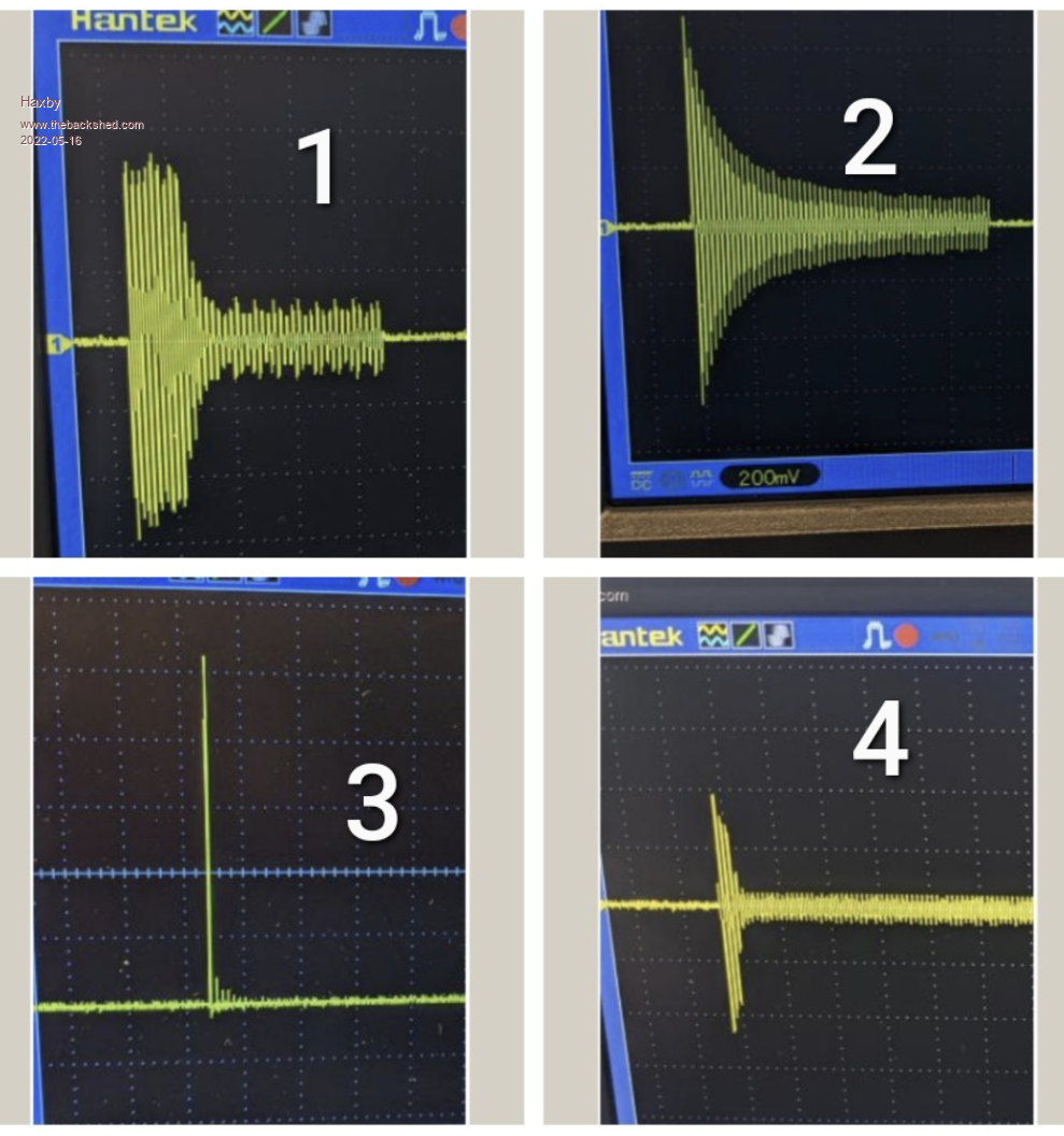 Graph 1: 2.2kw belt drive induction motor on a 50L air compressor: 50 amps for 300 milliseconds after startup Graph 2: Universal motor on a 255mm miter saw. 50 amps tapering off as it spins up in free air over around 500ms Graph 3: A big 2.5kw isolation transformer with no load connected. 100A for just one half of a 50hz wave! This one trips my RCBO when I plug it in sometimes. The transformer is of unknown origins. Graph 4: One leg of a 3 phase 2.2kw induction motor with 2kg of flywheel attached. 45 amps for maybe 150ms. Edited 2022-05-16 13:35 by Haxby |
||||
| Murphy's friend Guru Joined: 04/10/2019 Location: AustraliaPosts: 678 |
From my experience of blowing up Mosfets (and I have plenty of that  ) I would suggest that the type of mosfet you mention in your post is rather wimpy for the application. ) I would suggest that the type of mosfet you mention in your post is rather wimpy for the application.Here on this forum many inverter builders use HY4008's. On a decent heatsink you can use the rule of thumb of 1KW per 4 mosfet bridge. My big inverter uses 16 Mosfets (4 in parallel per leg) and can start up and run anything I have here. My experience with the TIP41/42 totem pole transistors was not good, they blow up far too easily. I replaced them with a type wiseguy uses in his inverter (I'm not at home presently so don't have the specs handy). No more problems with these. Haxby's pictures tell a very good story what your inverter has to cope with to start different loads. A tip: to avoid shrapnel and flame damage from exploding mosfets messing up your inverter innards use a pressure strip on top of them. I use a 20mm wide and 3mm thick aluminium (our spelling  ) strip for that. The mounting screw goes thru that, this strip is covering the entire mosfet(s) top and also providing a much better clamping pressure. ) strip for that. The mounting screw goes thru that, this strip is covering the entire mosfet(s) top and also providing a much better clamping pressure. |
||||
| poida Guru Joined: 02/02/2017 Location: AustraliaPosts: 1480 |
Here is the post I made showing peak DC current with the 1hp air compressor startup 245 Amps peak for a few cycles. This current is shared by 3 HY4008 FETs in parallel with 3 on the low side of one half bridge and 3 on the high side of the other half bridge wronger than a phone book full of wrong phone numbers |
||||
| InPhase Senior Member Joined: 15/12/2020 Location: United StatesPosts: 178 |
I do not use the TIP 41/42 totem pole scheme. The IRF21844 output from the nanoverter board drives a TLP351 opto gate driver on each FET. Since going that route, I have yet to kill the 21844s. But I killed plenty before optical isolation. I am desperately wanting to use standard available MOSFETs if it is at all possible. The HY4008 are not available domestically and are iffy if not sourced from very specific sources. My scope is a cheapo USB toy good up to 20 MHz with no capture feature. Also, the blow ups have killed all the FETs, but only the low side actually exploded this last time. I'll have it reassembled tomorrow sometime for more testing and will report back. |
||||
| Haxby Guru Joined: 07/07/2008 Location: AustraliaPosts: 426 |
Ok by the above answer, I gather that your USB scope can't be connected to both the high and the low gates at the same time, so you don't have a way of measuring the "real" dead time between fets while it's under load. Is that right? If so, it will be an uphill battle if you don't get one. That's something I went through this time last year. With no scope, I was armed only with a crystal ball and the good people of this forum. Sadly that wasn't enough, so after picking up the remains of more IGBTs than I care to remember, I bought a proper scope and two differential probes. No need to consult the tea leaves now. You get such a good view of what's going on, and you can really dial in all aspects of the system. The alternative is tears after tears, and only more and more question marks. Even if you get something working, you won't really know how well it's working, which opens you up to the dreaded intermittent fault club.... Works great for a while only to fail for no reason whatsoever seemingly randomly when you least expect it. By the way, TLP351 on each fet sounds to me like a bad idea. They take up to 700ns to turn on and only 0.6A. I'm not an expert on these designs yet so maybe more experienced members can confirm, but you need all fets within the same half bridge to turn on an order of magnitude or two faster than that. So you are only running 4 fets total at the moment? With a view to adding more? If so, your Bench grinder, if it's anything like my air compressor, will demand 250A on start up (on the DC side assuming 48v system). Photos please. Particularly of the gate driver stage. Edited 2022-05-16 16:53 by Haxby |
||||
| poida Guru Joined: 02/02/2017 Location: AustraliaPosts: 1480 |
THIS!! very much. I see it as a matter of how you cost your time. I am paid about $45/hr at work I pay myself same at home when working out "do I buy this DSO or not.." How many hours of blowing up and rebuilding things will it equate to some good gear that lets you see what is happening For what it's worth, I bought one modern differential oscilloscope probe first and that was all I needed (to see the gate drive on high side bridges) That and a probe on the ground referenced low side of the bridge can show all you need to see. 2 probes can come from old, obsolete, barely working due to bad caps etc. and likely out of calibration Tektronix A6902B Isolater. 2 channels, isolation well into 3kV. good stuff. My son has completed high school etc and so no more buying expensive textbooks. Sometimes they go for $100 each. Add it all up and you get the idea that education costs money. A good DSO and a good isolated probe is about all you need for this work with inverters and dc-dc converters, offline DC supplies (danger! 375V DC present) etc.. I won't pollute this thread with good probe technique. That is for another time. wronger than a phone book full of wrong phone numbers |
||||
| Solar Mike Guru Joined: 08/02/2015 Location: New ZealandPosts: 1228 |
Those TLP351 opto drivers have a +- 500nS variance between devices, if you use one on each mosfet then it is hit and miss whether they all switch simultaneously. Their 0.6A output is also rather low to be driving high capacitance input devices. If there is any large variation in timings then its quite conceivable that when placed in high stress, like turning on a high surge current motor, one mosfet will fail, followed by the others in cascade. I would test each opto driver in a circuit with a 20nF cap and paralleled resistor to make sure they are all transitioning within 10's of nSec of each other. Cheers Mike Edited 2022-05-16 20:24 by Solar Mike |
||||
| InPhase Senior Member Joined: 15/12/2020 Location: United StatesPosts: 178 |
Very good stuff fellas. I'll do some homework. Thanks a bunch! |
||||
| wiseguy Guru Joined: 21/06/2018 Location: AustraliaPosts: 1297 |
A schematic and a few pictures would really help as its a bit of a guessing game. I also concur with Solar Mikes comments re device parameter spreads with lots of opto couplers and no substitute for some suitable test equipment (borrow if you cant buy), and his proposed testing method. The gate drive resistor value can also cause issues if its too high. At the instant of turn on for the high side of a bridge, the instantaneous jump from zero to the positive rail can cause a lower FET/s to turn on due to its Drain to Gate capacitance causing shoot-through and disaster. Circuit layout, value of Gate resistor, a parallel diode with the Gate resistor to speed up turn off and lower its impedance when off can all help. I would advocate a single opto drive with a buffered output driving all the FETs. The transistors I used were 2SA2169 and 2SC6017 - they were on the endangered list at digikey, good for pulsed current ~ 13A. Schematic and pics please....... If at first you dont succeed, I suggest you avoid sky diving.... Cheers Mike |
||||
| InPhase Senior Member Joined: 15/12/2020 Location: United StatesPosts: 178 |
Also, sorry Haxby. I keep replying and not specifically answering your questions. I do not have a differential scope probe. The best I can do at the moment is measuring the two signals at the input of the opto couplers. Here's a couple of pics of the assembled unit and the FET unit it is based on. Keep in mind this is just a testing setup. I originally had the FET boards made to make use of high side switching for a few high current projects and I liked them enough I thought it was a good idea to use a bunch in parallel. I didn't even consider the propagation delay of the opto drivers. Back to the drawing board I guess! 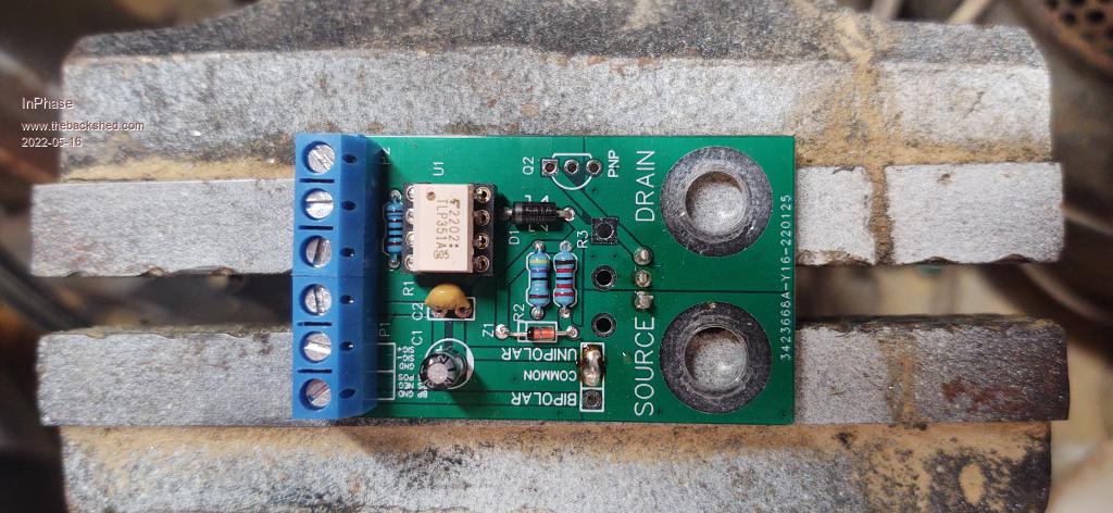 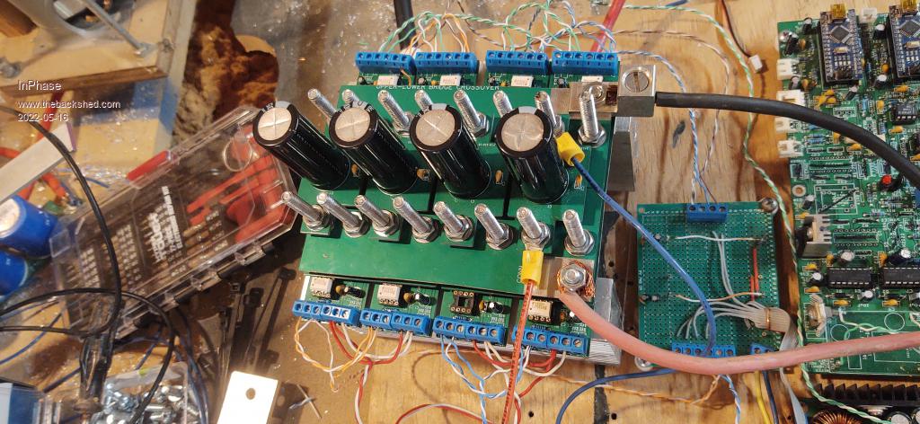 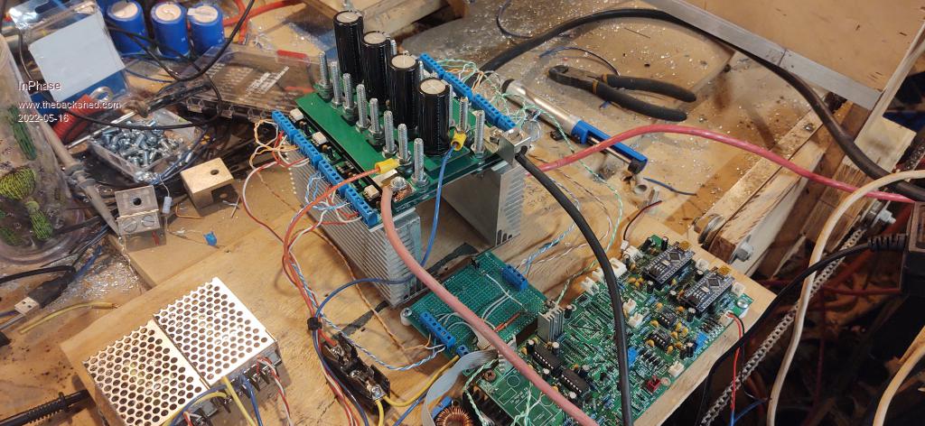 |
||||
| Haxby Guru Joined: 07/07/2008 Location: AustraliaPosts: 426 |
Ok so you are running 4 X 2 fets. Yep; likely the timing is out between the pairs. As for the fet types, I'd suggest ordering some beefier ones. Either from a reputable local supplier or from aoweziic on Ali express. |
||||
| The Back Shed's forum code is written, and hosted, in Australia. | © JAQ Software 2026 |
