
|
|
Forum Index : Electronics : Hopefully? Another 48vdc-240vac Toriod Inverter build.
| Page 1 of 26 |
|||||
| Author | Message | ||||
| KeepIS Guru Joined: 13/10/2014 Location: AustraliaPosts: 2196 |
Hello all, I thought I would start a thread on yet another 240vac Inverter build. The reason to start this now is the confusing statements on various builds concerning the expected use and capability of these Low frequency Toriod inverters. From what I have read on line and almost every forum, the typical High Frequency inverters are not any good at starting heavy inductive loads. I assume this HF inverter to be something like a "pure sine wave" 24/48vdc to 240Vac unit with a Hi frequency DC inverter generating around 360v-390v DC feeding a DC to AC PWM IGBT output stage and a large inductive filter for 230v AC. (No big Transformer) Strangely, I have a $680 made in China 5kW/10kW surge inverter just like this. It's a 24v inverter and it starts a big 25 year old massive 2.5hp air Compressor that was the bane of every work site if put on any kind of extension lead - used to burn out the motor from slow startup/stalling. The peak startup current in to the inverter of the above unit is 480A @ 26V. Expensive DC clamp meter with a slow decay hold function, a late model DC clamp meter and my own DC 600Amp clamp used to monitor the Load current with special peak hold coding for catching any glitch on the displayed graph at very high sample rates. It also starts our 2.5HP heavy induction motor Band-Saw at 410A surge, huge Bench grinder (induction), 2KW through wall workshop Vacuum, Air conditioner, Cloths dryer, small Oven, all workshop lighting computers, an so on, and until recently, a small 2.4kW water heater. I did have to strip that inverter down when I got it 10 months ago and fix all the poor finish and leftover aluminum filings, PCB gunk and poor fitting heat sinks, but it's got all high quality oversized components. Now from what I have read, this should have destroyed itself, and I thought so to, but it is what it is. I could not believe it could start that Compressor, had to go back and look to make sure it wasn't on mains. I want something that is not a ticking time bomb, hence my desire to build a Low frequency inverter, which is supposed to be the best with these kinds of induction load. But I see things like, you should soft start with these induction loads? seriously? you mean like a brownout condition? The Air compressor and Band-saw are just going to love that. So there are conflicting messages, and before I start on any big Toriod inverter build, I'm hoping someone can shed some light as to which information is correct. I mean 480A @ 26v is crazy and it HF inverter never misses a beat [YET]. I'm changing to nominal 48V so current will be halved, but I have an uneasy feeling after reading some of the failure modes of these LF Toriod inverters into complex high power shock loads? BTW: My wife has forgotten that we were on Solar and sometimes tries to start a Huge 3HP dust extractor, well it gives it a good try but the Surge time is only 3 seconds, so the Inverter switches itself off and restarts. The NVR relay drops out on the Extractor and no harm done, just switch over to mains to start the Extractor, can then switch back to Solar and all's good. Please don't read this as anything but an observation from way to much reading, and more a HELP call, or a Plea to enable me to make the most informed decision on how to proceed. I was going with the Oz inverter, but I saw the NanoVerter and Warp, and love some the brilliant work done on all of these but still some niggles? Yes I know it's asking a lot, but surely if a $680 24v HF inverter can do it without blowing up, one of these should. BTW: The HF inverter uses a slight variation of the EGS002 SPWM board, pin for pin compatible anyway, looks ALMOST the same. Have Toroids - can wind  I hope I hope  Mike. NANO:Inverter V 8.2ks - Linux AvrDude GUI script V4.1 |
||||
| KeepIS Guru Joined: 13/10/2014 Location: AustraliaPosts: 2196 |
Just sharing the result of testing some China caps, as others on the forums have already warned against. I could not get any good caps at this time and tried my luck with some China caps, turned out to be just crap. Test comparisons (older caps). Caps connected to a Linear Current limited tightly regulated supply. Current draw when fully charged over at least 10 minutes (if they weren't trying to self destruct). SPRAGUE 10,000uf 50v -likely 15 years since last used. @ 50V = 5ma @ 40V = 2ma ELNA 10,000uf 40v @ 40v = 0.25ma @ 30v = <0.1ma NIPPON 10,000uf 100v from Ali @ 100V forget it - way too much leakage - some quickly getting very warm. @ 90v most start to get warm, two drawing 100ma are getting close to running away with rising temperature. @ 85v 6mA to 20mA most slowly rising in temp after a while. Two really bad ones just keep getting warmer. @ 80v Between 3mA and 6mA and 6 of the 10 hold at that value. My feeling is these are 70V to 80V rated caps and not the 100V as advertised (or just crap). Might be OK for testing though as I will keep an eye on them, but not suitable in a final build. Would eventually cause an Inverter melt down on a hot day and/or sustained heavy load - even with forced cooling. Mike. NANO:Inverter V 8.2ks - Linux AvrDude GUI script V4.1 |
||||
Revlac Guru Joined: 31/12/2016 Location: AustraliaPosts: 1282 |
Hi Mike, Glad your starting your build. I have read that many times and don't really believe it anymore, but more head room is better for the unexpected extremely high surge. The ones I have used are sometimes referred to as AIO (All in one's) and are 48v 5Kw Runs the house no problems, The high voltage DC side is up around 430v last I checked. As far as not having enough power to start things, if kept within the design limits they seem to work ok. These things use about 50watts Idle current witch is quite high. So the challenge for me to build a good size inverter was to be much less than the 50Watts consumed but the HF inverter, as it turned out it wasn't that difficult to beat that. Also peak efficiency is a bit of a catch, typical house consumption is 300w-500w, best efficiency of the inverter I built was a little over 90% at 2200w. But the Home brew inverter will start some ridiculous loads that I use in the shed and very happy about that in many ways, also the biggest benefit for me is having separate from the house inverter on its own solar and batteries. The capacitors I used are 80v 10000uf Hi Temp NIPPON Chemi-Con and were Cheaper and the same dimensions as the 100v caps at the time. Any way have fun with it, will watch your progress with interest. Cheers Aaron Off The Grid |
||||
| mab1 Senior Member Joined: 10/02/2015 Location: United KingdomPosts: 282 |
Sounds about right: the start surge limitation is the amount of energy stored in the 360v capacitors - if they�re big enough the starting capability would be fine. Well 2.5hp is not that big for a 5/10kw inverter: my 5+ year old powerjack lf 24v 8kw/32kw (actually has 2�1kva transformer so nowhere near 8kw) will start a 4hp induction motor pressure washer. Actually, due to my ageing, small lead acid battery, my startups are now limited by the battery itself. I think it's more that you have to soft start the inverter when using a large toroidal tx; obviously it is desirable to soft start big loads but not practical for many. |
||||
| Murphy's friend Guru Joined: 04/10/2019 Location: AustraliaPosts: 678 |
Yes, it can be confusing for somebody who has not yet built a low frequency inverter. What happens is: you *must* slow charge the big capacitors from the battery when you connect it up first. Once they are charged up to battery voltage then you turn on power to the nano if you have the opto isolated version control board. This will slowly ramp up the AC voltage, you can see that on the scope or voltage display. Once its running and the display meter shows 230 (or so) Volt AC, its ready to start almost anything within reason. Building these things for the first time is a learning curve. It's quite easy to build a 'ticking time bomb', if you have no idea how this thing works you are at a big disadvantage here, better do some reading. I learnt as I went along, at my expense, with handfuls of blown Mosfets  marking the progress. So keep that in mind if you are reading my builds from a few years back. marking the progress. So keep that in mind if you are reading my builds from a few years back.I think I have figured it out by now  |
||||
| wiseguy Guru Joined: 21/06/2018 Location: AustraliaPosts: 1297 |
Hi Mike, welcome to the forum, I will add my support for some of the comments already posted. 1) Slow starts are not for the loads it is for the toroidal and avoiding a saturation and bang event. 2) Soft starting a compressor is asking for trouble in my first-hand experience it is the only way I killed my inverter with normal usage. The second way was playing with software changes, throwing caution to the wind and applying the changes to the inverter & Toroid without first bench testing waveforms with a CRO. 3) Always let the inverter finish soft starts unless the load is resistive, in my opinion inductive and capacitive loads should also only be connected after soft start is finished. Best to just turn on the AC circuit breaker manually for all loads after soft start is done. 4) I also have witnessed a 2kW HF inverter start fridges and all typical household devices for night-time usage without issue so yes, it is horses for courses. I suspect that either you got lucky with your choice of HF brand or it was just a lucky one or/and built really well. 5) Having used thousands of Nichicon capacitors for 20 years with voltages from 16V to 450V my experience is the opposite to yours, I am also confident that applying a brown shrink wrap to an inferior part but labelled the same as a Nichicon does not make it a Nichicon. Ali has some expert forgers for electronic parts, avoid capacitors, Mosfets and integrated circuits, yes they even Laser etch part numbers and logos to semiconductors and look like the real thing. 6) I went to the trouble of automating my soft charging of the input capacitors first before soft starting the inverter. Not implemented yet will be an output relay that connects the AC output automatically after soft start finish. 7) When I want reliable parts I buy them from Digikey, Element14, RS components or lastly LCSC especially for the HY#### Mosfets and all semiconductors to date (I have purchased) appear to be genuine. Have fun and please post your progress, successes and failures it's all good reading and helps others ! If at first you dont succeed, I suggest you avoid sky diving.... Cheers Mike |
||||
| KeepIS Guru Joined: 13/10/2014 Location: AustraliaPosts: 2196 |
Thanks for that tip, I've decided to try them, hopefully I'll have the same experience. Just ordered the HY devices. Most main stream CAP suppliers are out of Stock, however earlier today I found some on RS - took 2 hours of trolling though all of them to find some in stock. So I have spares to play with and destroy on a test inverter. Now I can blow Caps and FETS up like the Pros.  Also, thanks to all for the reply's I tend to keep questions simple and details short so I sometimes comes across a little vague. Soft start: Obviously inverters need an initial soft start due to the inrush current of the caps. I automated that with this HF inverter and that will be carried across to the new inverter. The HF inverter also soft starts the AC output, not what I want, however, instead of modifying it and switching that off, I again made a controller so that the Load is not connected to the inverter until it's fully running. That will also be carried across as it's external to any inverter. Fully understand the reasons to soft start the Toriod itself. I hate giving background info, but in this case it might help with my questions. I've worked with High Current AC, DC and Very High Current LV DC, high power RF and worked in industrial electronics most of my life, including industrial micro-controller programming, forgotten a lot of it as in, use it or loose it. The soft start question came up because there were discussions of specifically purchasing Manual AC ramp-up devices (manual soft start) for heavy induction loads in some discussion on these LF inverters, and that seemed to be a strange path to take. My current Solar system started out as a basic emergency supply to keep a small fridge freezer going and run a mains pressure water pump when needed. There were not many low cost 48v inverters around at the time so I went with 24V, when looking for a low cost solar charger I made sure it could handle 48V as well. I have 4 of these, I'm able to split battery banks and controllers should one part of the system fail (redundancy - I can see whats coming - My eyes are open). This 24v system will soon to be rewired for 48V - when I get the inverter running. I have 26kW of battery, so short term Load current is not a problem. Like most people, our average load is around 300w to 600 watts, with short periods of 1kW or 2kW. But I need to start that 3HP Dust Extractor. While 2.5Hp might be easy for most inverters, it's not when there are things like 60Kg of large diameter flywheel on the end of the shaft. The HP rating is not an indication of the stall current and the time that current is needed to bring up the rotational speed for the current to drop off. The 3HP extractor draws low current once it's spinning, but takes over 55A @ 240V to get that lump of steel hanging off the shaft moving. I love the idea of making it impossible for the the HI/LO side to conduct out of sequence and having dead time incorporated in the circuit. Using galvanic isolation between the control and Power PCB and bridge drive via 2 opto couplers "Warp" style parallel inverse driven to ensure each side cannot be commanded upper and lower on at the same time. This I believe was used / partly designed by wiseguy So I'm still a few weeks from starting on the transformers and I also note that the thoughts on winding turns and ratio has shifted a little (or is that settled / converged) as more understanding of feeding and caring for your Toriod has evolved. There is such great real world testing and effort put in by members of this Forum (and across other forums as well) and there is only so much information one can take in after weeks of reading every word of these, some fault finding posts are almost like a mystery novel, I was compelled to read to the end and find out "who done it". Again thanks for any input, I find as I get older there are occasional senior moments, (the drugs will do that to you) fortunately got off those as fast as I could, much to the dismay of the Doctors - Well, tough, get over it. � Mike. Edited 2022-12-26 13:13 by KeepIS NANO:Inverter V 8.2ks - Linux AvrDude GUI script V4.1 |
||||
| KeepIS Guru Joined: 13/10/2014 Location: AustraliaPosts: 2196 |
Definitely going to follow oztules advise and open the Cores out to at least 100mm. I will use the one AeroSharp Toriod I have with it's remaining 230V winding as the test unit. Mike. NANO:Inverter V 8.2ks - Linux AvrDude GUI script V4.1 |
||||
| KeepIS Guru Joined: 13/10/2014 Location: AustraliaPosts: 2196 |
I have a working 48V china inverter board that I plan to use during testing, it auto detects the supply 12v to 48v. However a while back I was given a smaller 24V board and would like to use this for testing at 48V, saving my more powerful board for final testing. Somewhere in the Forums I noticed a question about changing a typical China Inverter board from 24v to 48v. The person giving advise certainly had a lot of knowledge about these type of inverters. I'm hoping I can get an opinion on this unit. The exact same unit appears to be sold for voltages from 12v to 48v (select voltage, freq and checkout). The Filter caps and all supply caps are rated at 80v to 100v, main filter caps are 100v. It has adjustable over voltage, under voltage and may only need a resistor change to each preset adjustment pot to bring it into range? The nominated battery supply appears to run to an switching regulator?, I assume a resistor change should solve that but before doing anything, I thought I would reach out to the forum for some help or input on this. 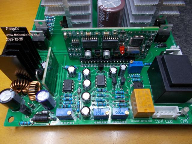 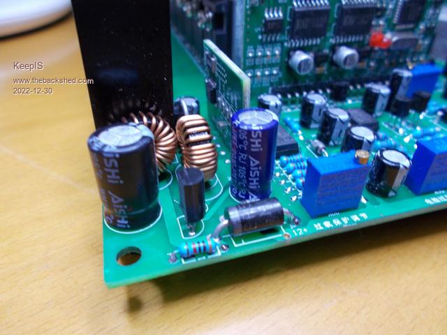 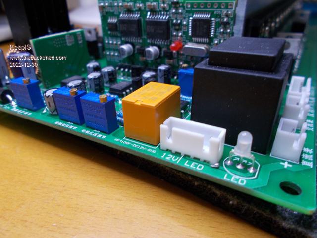 Thanks. NANO:Inverter V 8.2ks - Linux AvrDude GUI script V4.1 |
||||
| KeepIS Guru Joined: 13/10/2014 Location: AustraliaPosts: 2196 |
I've been looking at your post "my inverters are different". I can see the opto isolated drive and the totem poll there. Have you or wiseguy published a complete circuit for that, also revisiting the Nano build, been reading everything by Poida and Wiseguy, but trying to pull it altogether up to the current state of development is kinda difficult. I love everything about your build and design for so many reasons, wondering how this is running and how hard it has been pushed, any info would be really appreciated. Really starting to sway me, my only concern was the stability of the Micro controller in such a noisy environment, obviously isolated power and drive really help here. I sure about reviving an old post so I asked the question here. Mike. NANO:Inverter V 8.2ks - Linux AvrDude GUI script V4.1 |
||||
| wiseguy Guru Joined: 21/06/2018 Location: AustraliaPosts: 1297 |
Mike I agree that my build and its trials and tribulations are a bit hard to follow as I have not presented it as a finished project as its still a work in progress. �The most recent encouraging discovery is that I unwound a couple of turns from my choke in series with the Toroid to see what would happen and the grunt was about 1/3 of its previous volume. I also noticed the idling current went up a little bit - from memory ~ 15% but it was still very respectable - I don't have the figures with me I'll guess from ~11.5W to ~13W. �I wanted to investigate this further but need to get at my bench, I am currently having "quality" family time on holidays......dreaming about the workbench and stuff I was dragged away from and am missing �  As my situation & need is a bit different to others here, my need for an inverter has taken a bit of a back step. The Tektronix current probe amplifier I had, was always difficult to work with as the calibration shifted with different range/sensitivity levels and was a pain in the proverbial, so I spat the dummy and dismantled it enough to find one of the printed Laser trimmed ceramic precision X2 50ohm multi switching attenuator networks, which is a "T" resistor setup and the one to earth was open circuit. So I ordered another amplifier unit for "parts" only, so I could repair my unit. This has taken nearly ~ 3 months total to finally have my amp working & calibrated perfectly. Some helpful sod had also tweaked some of the internal settings in an attempt to fix it, which all needed to be reverted. I am telling you this tale of woe as I got to the stage of wanting to do a bit of an in- depth investigation of the inverter transformer's choke to try to get the best "goldilocks" solution and needed a reliable current probe to see what was really going on. �I was encouraged that just taking a few turns off my choke had made such an improvement. �I believe the final success of my inverter rests with the correct choke solution Im not sure that you or anyone really wants my total solution though, my choke I expect will use sendust toroidal cores or and possibly a few EE65 gapped cores. �I am not going down the iron core path unless all else fails - it's a me thing...I will concede though that adding some milliohms of resistance in series with my sendust choke did reduce the grunt a little, so a more lossy choke is not all bad. Murphy duplicated the Warp inverse opto FET drive part also and has been trying to kill FETs ever since, but I believe a solution to this has eluded him to date. My controller board uses the little 2mA/2ma voltage sense transformers and I currently have 2 working versions for the inverse opto drive, one with the EG8010 IC the other using Poidas nano code. I would probably advise the nano version and if you want to play with some ready-made (blank) circuit boards I could also help with that. What does your idea of a finished inverter look like in your head, and how much of it do you want to roll your own ie pcb design etc etc. �If discussing in the Forum has any issues for you and you'd prefer a couple of PM's that's fine too. �But ultimately success or failure is all good and published results are all helpful to others in the Forum. Edited 2022-12-31 06:53 by wiseguy If at first you dont succeed, I suggest you avoid sky diving.... Cheers Mike |
||||
| KeepIS Guru Joined: 13/10/2014 Location: AustraliaPosts: 2196 |
First off Mike, thank you for taking the time to reply whilst on holidays, I know that feeling of missing the project calling you back to the work bench. Actually, I found your build logical and easy to follow, I could see exactly where you were coming from, same as Poida, but it's like the last few pages of two detective Novels are missing - I'm looking for the Happy ever after ending I look forward to your investigation into that dam Choke, it appears to be one of the last areas that has a "luck factor" about it. The brilliant in depth testing by yourself and Poida into failure modes is something I am passionate about, as are a few others now. Leaving aside the build quality and mistakes made in layout and construction, to me as least, it's looking like that area of interaction between the construction and electrical "stiffness" of the transformer [tiring to think of the correct term for that] and the Choke in the complex interplay of restive, inductive and capacitance effects in Home AC wiring, and everything between the transformer secondary and the various connected idle and running loads on each build, is the Gray area that makes or breaks the same inverter builds, why some work perfectly and others go bang? I was also planning to test a choke using 4 of the E64 cores (gaped). I'm just building a few Jigs for testing FET voltage, current, heat and RDS limits and then matching as close as I can from the 80 odd FETS that I have here, and a Jig for the Choke inductance. I came across Gaspos little board that plugged into the OzInverter board and apparently solved the shoot through issue, I was going to see if any were available, however I will go over your posts again (all downloaded in PDF) and look at the inverse opto drive. I would love to take up your offer and purchase the blank boards for the nano from you. I was just going to order a couple of Nanos to play with, so dam impressed with Poidas code and yours, Madness and Warpspeeds input on that - love the group think posts, apology if I left anyone out. I'm a bit like Murphy's friend also love the construction side as well, so I'm not trying to make something compact. This will be a heavy unit, and I normally do a Cabinet on wheels to allow full access like Murphy's friend did. I've always found that the easier something is to fix, the less likely it is to fail. I have the OzInverter boards and will likely use the power board, but change the screw caps to the bottom of the board, use bigger heat sinks and a different connection setup to the control board. I can modify almost anything without electrically compromising the operation of the inverter, even under the highest load conditions (including noise - RF and induced). I fully appreciate why the OzInverter board was made this way, I think it is brilliant for what it set out to accomplish. I, on the other hand, would like to have four separate power boards as per Murphy's last build like the WarpInverter construction, but like I said, getting boards made at the moment is difficult for me. This is the reason I want to get the Transformer right, then construct the inverter in a such a fashion that allows me to easily change the driver and power board layout if needed. Everything will be tested in stages then run up with NO caps, current limited supply and lots of Oscilloscope (digital and analogue) testing. That's also why I'm trying to convert the 24V inverter to 48v that I posted above. Get the transformer and choke tested and adjusted running at high power and blow it up first (hopefully not). Mike. NANO:Inverter V 8.2ks - Linux AvrDude GUI script V4.1 |
||||
| Murphy's friend Guru Joined: 04/10/2019 Location: AustraliaPosts: 678 |
You wish, Mr. Wiseguy  , but I have long since got my converted to opto isolated drive inverters (4 off) running perfectly . , but I have long since got my converted to opto isolated drive inverters (4 off) running perfectly .The big, dual stack, 6KW inverter is on standby connection while my house is powered from my warp inverter. I can be switched over in 30 seconds. The reason for this is that I use both, MPPT charging and GTI back charging to fill up my battery bank. Now, both inverters work with that but the 6KW dual stack growls fearfully while 2 or so KW of power is being pushed backward through it. The warpinverter just hums a little louder in the same scenario, that is why it runs the house since I have a choice  . .One rule of thumb for prospective inverter (non warp) builders that I found is that a full bridge of 4 HY4008's can handle 1KW on a good heat sink. My big inverter has 4x4 (16 total) HY4008's, so 4KW but a lot more intermittently. The warpinverter uses 4 full bridges, 16 + 12 + 8 + 4 = 40 HY4008's to compare, it's a lot more expensive build .My early inverters used TO220 mosfets, up to 6 in parallel but that many proved messy when they went chain reaction 'bang'. So I suggest 4 x 4 in parallel for Mike's build. Mike, you might re consider your 'ozinverter power board' when I tell you that half bridge PCB's use the Aerosherp heat sinks much more efficiently and one can build them with a non live heatsink. You *do* have to be able to accurately drill & tap thru & blind holes in the heat sink to build an inverter that way. |
||||
| KeepIS Guru Joined: 13/10/2014 Location: AustraliaPosts: 2196 |
Thanks for the information. As I won't be using GTI back charging that is one less thing to deal with. The power bank is 25kW of LiFePO4 Dual BMS batteries with equalizers. I would like to go to with 4 power boards, much cleaner build and optimizes the heat sink and layout. But there is that problem of getting boards. I have full workshop drill press and taps, been designing and building electronic equipment since my early teens so not a problem from the construction point of view. I only have one Aerosharp heat sink, but have four of the big SMA units (almost as big), and one huge heat sink that makes the Aerosharp look positively tiny Power wise I need to handle up to 15kW for a few seconds, maybe 3kW to 4kW 5% of the time and <1kW 95% of the time. Anyway all good info, I have a bit more reading to do, but getting to that stage of having a really good understanding of the nature of the beast, having reached that point I am now deciding how I want to implement the build, so nothing is cast in stone yet. I am going to use 3 x 1.2kW SMA toriods stacked and opened out to at least 100mm. Wind them to a flux density of 1 Tesla and favor low idle current, the cores should handle 15kW inrush current to the Induction motors starting heavy shaft loads. The Current 5kW HF inverter can handle the the 12kw startup of the Compressor, 10kW Band Saw but can't quite hold the bigger load of the Huge 3HP Dust extraction system trying to spin-up the massive Steel Fan. It just needs another second or so and it would have it running. Still find that amazing, especially from 24v HF inverter. Of course the New inverter will be running at 50v. NANO:Inverter V 8.2ks - Linux AvrDude GUI script V4.1 |
||||
| wiseguy Guru Joined: 21/06/2018 Location: AustraliaPosts: 1297 |
Ok I admit I was a little (a lot?) confused. The discussion started with HF inverters and when I saw the mention of nano-verter I read it as the nano HF inverter. So most of my comments and information were related to HF not the LF? Warpverter in my posts. I reread the first post more carefully again and think the part that did it was: " before I start on any big Toriod inverter " and after that I assumed incorrectly that it was an HF inverter single (large toroid). There was discussion of both types and after re-reading I realise I was on the wrong path so apologies. If you do want to build an HF inverter sometime, I'm happy to help further then - I don't have any Nanoverter/LF/Warpverter control boards. PS: Happy New year to all BS'ers lol Edited 2023-01-01 10:04 by wiseguy If at first you dont succeed, I suggest you avoid sky diving.... Cheers Mike |
||||
| KeepIS Guru Joined: 13/10/2014 Location: AustraliaPosts: 2196 |
The confusion for me comes from the lumping inverter with Solar inverters, low voltage inverters 12v to 48V? and not just the frequency, LF inverter should be to me as least, an inverter running internally at 50hZ/60hZ, but most (not all) refer to LF as a having big transformer and HF no big transformer. Both Solar and 12V-48V inverters. From a quick search � � � � This link below, to me, is a HF inverter as it's based on the EGS8002, 25kHZ & 50/60 Hz (or what ever) but many forums and web sites refer to this an LF inverter? which is the mistake I obviously made. � � Inverter Driver board This inverter below is what I refereed to as a HF inverter, a LV DC to HV DC input board and a HV DC to 240Vac board - No Large Transformer. Likely wrong term by me again. DC inverter input: 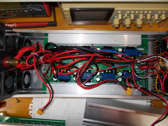 AC pure sign wave output: 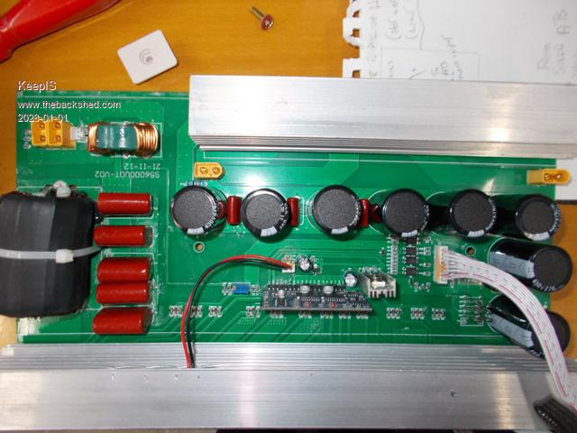 � Soooooo, I want an inverter based on an EG8010 OR the Nano version of this, driving a Stacked Toriod. 48 VDC input - 220 VAC out. Like the OzInverter, is the Nano version different? Apology for any confusion. Edited 2023-01-01 14:32 by KeepIS NANO:Inverter V 8.2ks - Linux AvrDude GUI script V4.1 |
||||
| Murphy's friend Guru Joined: 04/10/2019 Location: AustraliaPosts: 678 |
The latest version Ozinverter runs of the EG8010 chip. Originally it used that cheap plug in little PCB we had lots of trouble with unless it was modified. That was a lot of trouble so the chip only was used on a generic carrier and the other components added to make the brains of an inverter. The nano inverter replaces this chip with a nano and runs with Poida's program. Originally the nano fed signals to the drivers (various types) which in turn switched the Mosfets. The opto isolated version has that extra safety feature of eliminating shoot through completely. It also uses more suitable totem pole transistors than the ozinverter. You mention PCB problems, is that because you have no experience of laying them out or you do not know how to order them from Gerber files? If you have specific questions about my PCB's for one of the inverters I posted here send me a PM. |
||||
| Murphy's friend Guru Joined: 04/10/2019 Location: AustraliaPosts: 678 |
FYI, My inverters use 2 power boards (2 half bridges), 2 half bridge driver boards and suitable mosfet carrier boards for easy replacement of them. Have a close look at my pictures. There is one control board holding the nano and battery management parts plus VFB & IFB input. I use a little PCB for the VFB transformer/ rectifier and current sensor/ rectifier. One full 3KW Aerosharp heatsink cut in half will do for your load, coupled with a 120mm fan. I use Ebay temperature control relays, not the nano, to control the fan as Poida & others do. |
||||
| KeepIS Guru Joined: 13/10/2014 Location: AustraliaPosts: 2196 |
Thanks, I'm aware of the problems with the from China "complete boards" using the EG8010 chip, and the EG8010 carrier board and control board used on the OzInverter. Thanks, will definitely keep that in mind. I had a good look at your last build and I did notice the way you had laid it out and you desire to make it your way, including the boards, great work. I'm talking to Wiseguy and clearing up the misunderstanding, so I think I can see a clear path to travel. This will likely be slow process, at my age it takes a bit to get over two successive heart attacks just a few months back, but this kind of thing helps keep my mind focused and away from where I don't, and should not, let it go. I think unwinding and rewinding those Toriods will be a bit like Basket weaving therapy  NANO:Inverter V 8.2ks - Linux AvrDude GUI script V4.1 |
||||
| Revlac Guru Joined: 31/12/2016 Location: AustraliaPosts: 1282 |
Hi Mike, Thanks for sharing the pictures of your inverter (guts) as expected it is different to the one I use, I always assumed that the reason it was called a HF inverter was because of the High Frequency converter inside, low voltage DC to high voltage DC, then from the High voltage DC rail they run 4 IGBT's to convert it to AC output, some are referred to as using chopped DC, other's I'm sure are more like a normal inverter just running from a high voltage DC supply. I could post a photo of the one I had (it has a single transformer in the converter) but that would be straying off topic a bit. Actually there is a better explanation by SpongeBob https://diysolarforum.com/threads/idle-no-load-consumption-specs-vs-your-personal-observation.31747/page-5#post-674182 interesting read. Cheers Aaron Off The Grid |
||||
| Page 1 of 26 |
|||||
| The Back Shed's forum code is written, and hosted, in Australia. | © JAQ Software 2026 |
