
|
|
Forum Index : Electronics : Hopefully? Another 48vdc-240vac Toriod Inverter build.
| Author | Message | ||||
| KeepIS Guru Joined: 13/10/2014 Location: AustraliaPosts: 1877 |
Hi Aaron, Those pictures don't do it justice, it's a lot bigger than it looks. It's is pure sine wave output stage using an egs002 board. With 12 IGBT's in the bridge output. Thanks for the link, he described it as I saw it and how it got mashed up on the inter web of truth  NANO Inverter: Full download - Only Hex Ver 8.1Ks |
||||
| KeepIS Guru Joined: 13/10/2014 Location: AustraliaPosts: 1877 |
Just received some "Brand Name" 10,000uf Electros from one of the big prominent AU electronic suppliers. Running at their rated voltage, the current drawn was less than 45ua (microamps) and slowly dropping. Unlike the NIPPON 10,000uf 100v from Ali: None could run at the rated voltage - way too much current drawn and some starting to heat "big time". I had to drop the 100v rating back to 80 volts with a 3ma to 6ma draw, but still very slowly rising. If caps were warmed, the current started to rise faster then I would like. It's not if they will fail, only when and how quickly it will happen. I could never leave an inverter running unattended with those obviously fake caps. Even cut one open to make sure there wasn't a smaller cap hiding inside.  Edited 2023-01-06 18:39 by KeepIS NANO Inverter: Full download - Only Hex Ver 8.1Ks |
||||
| phil99 Guru Joined: 11/02/2018 Location: AustraliaPosts: 2626 |
In the "Good Old Days" it was usually necessary to re-form the dielectric of electrolytic caps. if they had not been used for a while, including new ones that have been in storage too long. You hook them up to their rated voltage via a resistor to limit the leakage current to a few mA and leave them like that for a few days. For big caps like yours perhaps a week would be better. When the leakage drops below 100uA they should be safe to go into service. If the leakage has risen after that time bin them. |
||||
Revlac Guru Joined: 31/12/2016 Location: AustraliaPosts: 1153 |
Big difference, in the real quality gear compared to the unknown quantities on Ali. I just tried 1 of the 80v 10,000uf nippon caps, (I only had 60v batteries on the bench) tested at 60v and it was .3ma and dropping, not a great test, I expect worse at a higher voltage. Could be anything under the plastic cover, also a seller could have better quality one time and not the next.  Edit Checked the cap to see how it was holding voltage, 1:30AM it was 40v and 7:30 this morning it was 36.5v in the cap. Edited 2023-01-07 07:28 by Revlac Cheers Aaron Off The Grid |
||||
| KeepIS Guru Joined: 13/10/2014 Location: AustraliaPosts: 1877 |
Yes, they still have the reform procedure in the technical data that came with the caps, as you say, exactly the same way we did it years ago. The new caps are below 45uA after 30 seconds, no problems there. I tried reforming the nippon caps I had, also tried it at a lower voltage (always current limited) but five of them never dropped off below the 5mA current limit. When connected at their rated voltage after both reforming attempts, some immediately started to go into meltdown. They were the correct rated capacitance, you could arc weld with them, just totally unstable unless running at 2/3 of the voltage and very temperature sensitive. If I had used them in a 48V (nominal) inverter build, they would have worked perfectly running at half their rated voltage, BUT - and it's a BIG but, any increase in heat, either self generated (heavy loads with high ripple current) or external heat from the rest of the inverter (likely both) and they would have eventfully exploded. God forbid running them in a loaded inverter on a 40deg summer day. Aaron, interesting thing is, they held a partial charge, once the voltage dropped a bit the leakage current was low, but I never noted the voltage as it was a spur of the moment check before I put a screwdriver across the terminals to hear them go splat, and they did, then promptly threw them in the bin after cutting one open. NANO Inverter: Full download - Only Hex Ver 8.1Ks |
||||
| KeepIS Guru Joined: 13/10/2014 Location: AustraliaPosts: 1877 |
Following on from a question I asked on Page 1 of this post, it was about converting a 24v inverter to 48v. I traced out the circuit of the 12v main switching regulator. It appears to be able to run with no change from 6v to 60v. That would make sense, it makes it easy for the supplier to make one board to cover �12v to 48v or more, and change a link for 50/60hz option, it appears that all they do when you select a voltage option is adjust the Low voltage and Over voltage cutout pots to suite that voltage. I ran it up to 60v (no transformer and the control the board stays turned off) and everything was fine. Regulated 12v was perfect and the switching regulator was happy, no change in Reg PWM wave shape. The Reg uses an IRF540N and a tiny control board has an 8 pin surface mount chip and a few passive components, could actually be a 555. The newer inverters that auto detect input voltage (12v to 60v) use the exact same 12v switching regulator, they auto set over voltage and low voltage cutouts (no adjustments) and you only select the frequency (50/60) and the battery type for the unit you purchase. � � � BTW ALL caps are rated at 100v where they need to be. � As a refresher, the pictures of my 24v unit in question. 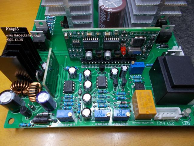 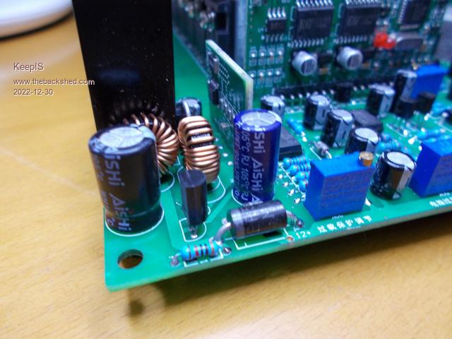 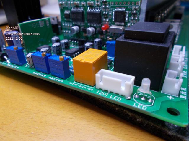 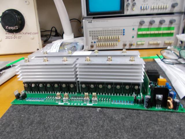 So this should give me something extra to play with at 48v. Edited 2023-01-07 18:15 by KeepIS NANO Inverter: Full download - Only Hex Ver 8.1Ks |
||||
| KeepIS Guru Joined: 13/10/2014 Location: AustraliaPosts: 1877 |
Playing around with the Toriod from the Aerosharp. This will be my test Toriod during the build. The outer winding removed leaving a 230V winding and a screen, might remove the screen and add a few turns to bring it up to 250 or 260v if needed. Wound a single primary of 8awg 7.5mm2 (56A rated) Core is 0.98v per turn and I wound 27 turns, using my big old VARIAC I got 26.4vac @ 220V, could wind a second but one winding is enough for testing and also for the lower power 230Vac winding. Just wondering if I should drop that to 25V? Although my LiFePO4 battery bank will likely never go below 50V. Quick test for about 30 seconds pulling 50A @ 25.3v into big dual 300mm x 70mm power resistor load (toaster element on steroids), obviously not enough to heat anything but the load. There was a Cap supplied with the China inverter, using that, I have a very noticeable resonance peak at 76Hz with the 4uf Cap, close enough for me. The parts for the inverter I'm building, one of Wiseguys designs, are coming in surprisingly fast from China and other locations, some parts were down to the last few left with many sites showing NO stock I think I got in just in time.Just for laughs a picture, I know it's not much, but for me at this moment in time it's a start, and another small step, just got to keep taking those small steps. 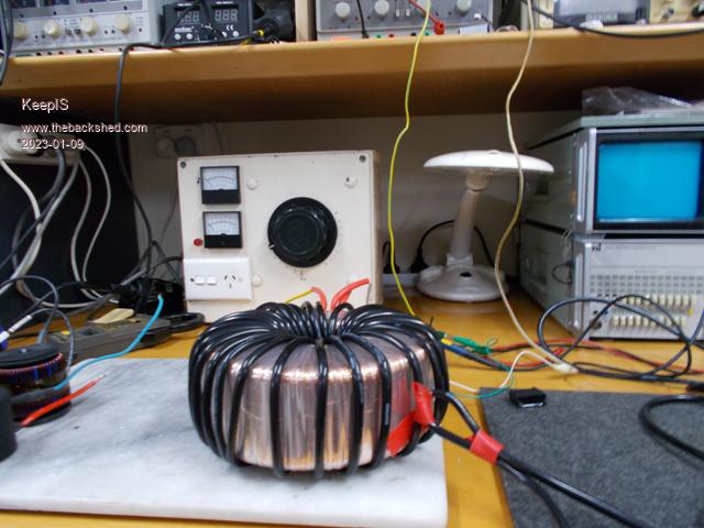 NANO Inverter: Full download - Only Hex Ver 8.1Ks |
||||
| KeepIS Guru Joined: 13/10/2014 Location: AustraliaPosts: 1877 |
I'm trying get familiar with testing and measuring a running inverter and Toriod, particularly when powering one up in a safe manner to avoid the dreaded splat. The Ferrite E-core arrived a week ago and it was broken! just paper thin bubble wrap and from a big name AU supplier, sent a picture and waiting for a replacement to arrive. In the meantime I wound 7 turns of the primary lead through the core, left a gap and taped it together. The inverter for testing is marked 24v, but it should be good to go at 48v, however I had to change a resistor in the over voltage circuit to get the cutoff up to 59 volts. Appears the hi/lo interact and I will now need to change a resistor in the low voltage cutoff, at the moment it's at 44v and the turn on voltage is 51v, need to get them up a bit. Powering the unit with an adjustable 0-60v 0-4A supply, so cap inrush etc is taken care of. I'm not going to try and remove the 11 caps on this board, 11x 1000uf, only 11000uf. I placed a 22 ohm 10w resistor in series with the choke to limit current into the toriod and slowly bought the voltage up with the on/off inverter switch on. Inverter started at 25v and a small lamp on the 220vac side lit up. Secondary waveform looked good on the CRO. Spent some time adjusting and replacing a resistor to get it running at 56vdc. After I was sure it was fine, I shorted the resistor in series with the Choke and left it run for a while. No Load power is 13.4w (56V @ 240mA) As I'm limited to around 200watts input at the moment, I decided to plug the Variac into inverter. This Variac has a really Big Heavy toriod and I was vary wary about what this load would do. Provided the Variac is at Zero, it's fine, flicked the over current on the supply when powered on [expected] and as it's a current limited supply, it holds at 4A and drops the voltage to maintain 4A, however the Inverter ran fine. I use a Heat Gun set to high and adjusted the Variac up until the 4A current limit led was flickering, left it for a few minutes, waveform still good, however Variac was really noisy if the Load was switched off, but quite with the heat gun on. Also the inverter waveform was very bumpy on the leading and trailing slopes with no load on the Variac. I noticed this noise with the main inverter that is powering the shed, although it's noisy with the load as well, Variac is relatively quite on mains. Must look at the waveform some time. There is quite a lot of load on the main inverter so I thought that it may have dampened the Variac noise, but no. As a result of this initial test, I know what conditions it will startup under, typical current draw during startup, and there is nothing like looking at waveforms yourself. Another thing that I did notice, they have one temperature sensor on one of the two smaller (separated) heatsinks, that heatsink had a slight warmth to it, whereas the other half and the full heatsink were cold after a few minutes running at 200w? Have not done the suggested mods to the EGS002 board yet, going to review the circuit to EGS002 board interface and make sure that any changes will work with this inverter as well. EDIT Must have fluked the temporary choke, broken core and all, without the choke idle current is 1.4A = 78 watts, added a turn and up slightly, took a turn off and now 230mA = 12.8 watts. Edited 2023-01-10 18:44 by KeepIS NANO Inverter: Full download - Only Hex Ver 8.1Ks |
||||
| Revlac Guru Joined: 31/12/2016 Location: AustraliaPosts: 1153 |
Looks like it is working well,  �I have heard of a few E Cores being broken during shipping, some were just glued back together. �I have heard of a few E Cores being broken during shipping, some were just glued back together.You have a photo of it? If you want to see the sine wave wobble, try a variable speed drill or a soft start grinder, works ok at full speed.Actually I Didn't get the same wobble on the HF inverter, will have to check LF inverter again and see. Edited 2023-01-11 09:02 by Revlac Cheers Aaron Off The Grid |
||||
| KeepIS Guru Joined: 13/10/2014 Location: AustraliaPosts: 1877 |
I can post a small photo, but looks like the wobble is caused by the choke interaction with the Toriod, I changed turns until I got low Idle and then adjusted for best waveform, and now it's almost textbook sine wave. I'll post one later as I'm now trying to measure the saturation and playing with the gap to increase current before saturation. Of course will have to do it all over again when I make a new toriod. but at least I'll be used to setting it up. Yes, I plan on gluing it together if they don't ask for it back, but the replacement may be just the one core though. 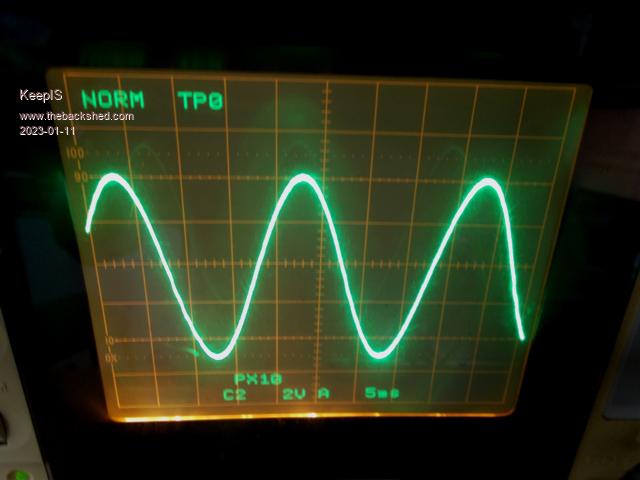 Edited 2023-01-11 19:21 by KeepIS NANO Inverter: Full download - Only Hex Ver 8.1Ks |
||||
| poida Guru Joined: 02/02/2017 Location: AustraliaPosts: 1432 |
Hi there, It's good to see someone new building an inverter Maybe you can use some of what follows, maybe not.. re: primary winding LC tank behavior We choose a cap and choke to make a LC tank resonate at X Hz where X can be anything but 75 Hz is preferred by some people here Even without a choke, there is non-zero inductance and this comes from the leakage inductance of the transformer. This can be increased if we want by bunching the primary windings together, rather than spacing them equally. Victron's 3kW inverter uses this principle with it's 2 very undersized toroids to get enough inductance in the primary winding LC tank. They do not have a choke in the primary circuit. They do have a cap of course. Most builds here use a toroid with very low leakage inductance and so need the choke. I blew up inverters due to the choke's parameters not suiting the needs of 1. resonance above about 45 Hz and 2. not saturating at peak power levels The choke used in the (3 year so far) working inverter uses 2 of thelarge E cores, with a 1mm air gap in the middle pole. They need about 7 turns to get 40uH and they are wired in series. Testing showed little saturation at 80 Amps and moderate at 90 Amps. The 50V supply x 90 Amps means about 4.5kW peak power Logged data shows DC peak current drawn by the inverter does not exceed 90 Amps so that's no. 2 sorted. I blew it a couple of times when I had a resonant freq of about 10 or 15 Hz. Once enough choke is built, I had to choose a small enough cap to give me something more than 45 Hz. Once that was done, the inverter survives. The cap I use is 1uF or maybe .68uF, I can't recall During testing I found, and I have no doubt you will see too, that tuning the LC resonant freq. will give different idle current losses. From memory I think the lowest losses were with a too low freq. The output waveform also is effected by this. I choose the primary winding components in order of choke (non-saturating at peak loads), cap to get freq up to 45 or more Hz, and live with the waveform I get and idle losses. re: the inverter board you are using You chose the most robust design, the one with totem pole drives close to the FETs The EG002 control board uses IR2110 gate drive ICs, these produce a reliable signal drive including deadtime. Their output pins are quite sensitive to voltage excursions beyond specs keep it above -0.3V Vss and below Vdd + 0.3V Some inverter boards do not have the totem pole drive and so this means the FET Gate drive is direct from the outputs of the IR2110. Sadly, these lines on the PCB pick up a lot of EMF and the IC output pins see voltages outside the safe range. The inverter runs fine, for a while. Maybe a month, a week or a day. I had failures after all these 3 periods when using those boards. Failures stopped when I placed fast acting diodes on the outputs, close to the ICs, preventing the under and over volting. I did some careful testing of voltages of gate drive, at the IR2184 (as used in the nanoverter), the base pins of the totem pole drive and the Gates of the FETs, under various conditions. I wanted to see if there was still a risk of under/over volting the FET drive IC outputs. No risk when using totem pole drives using the TIP41/42 transitors. The EMF spikes seem to be attenuated or clamped when passing back to the gate drive ICs. wronger than a phone book full of wrong phone numbers |
||||
| KeepIS Guru Joined: 13/10/2014 Location: AustraliaPosts: 1877 |
I wondered if a small cap at the output of the choke might help roll off signals > 20kHz, but once a value was high enough to make a change, it was for the worse, more noise on the waveform at the output from the choke - values from .002 to .1 tried. Looking at the output from the Choke, I adjusted the inductance of the choke for the lowest noise, it only raised the idle current by 30ma and required an extra two turns, but really cleaned it up some. I find that a second choke in the Lo bridge to toriod lead, while making the waveform slightly smoother, resulted in an occasional spike on output waveform (240V out) when the load was witched on or off, but not all the time, it does not happen with just one Choke, I even tried reducing the inductance of each choke in case I was seeing an inductive spike, but made no difference. Just out of interest, when the single choke is moved to the Lo side, the AC output has that very noticeable familiar ripple, I thought it would be a lot worse, and still runs fine, but again only tested with a light load, I'm limited to a few hundred watts at the moment. Yes, I put choke back on the correct High side. Before the choke. 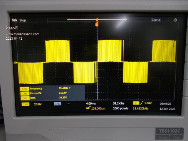 After the Choke (primary of toriod). 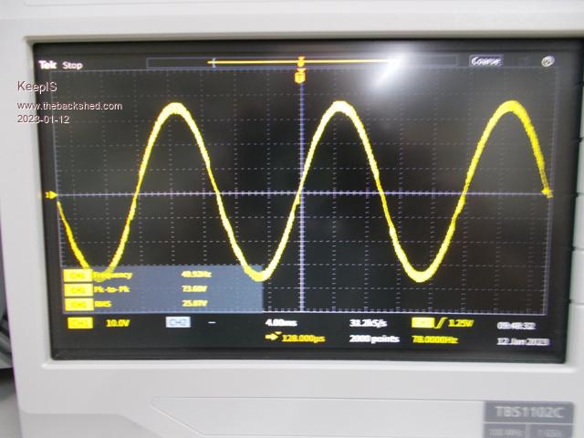 AC output. 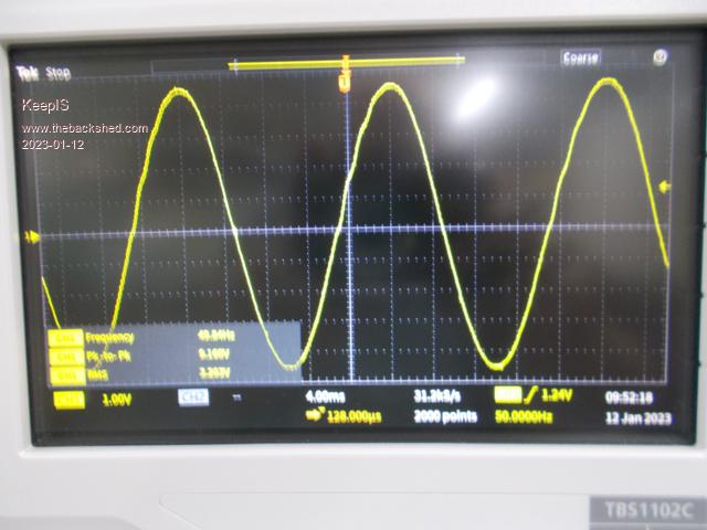 Apology for bury images. Edited 2023-01-12 12:17 by KeepIS NANO Inverter: Full download - Only Hex Ver 8.1Ks |
||||
| KeepIS Guru Joined: 13/10/2014 Location: AustraliaPosts: 1877 |
I have 2 Ferite core chokes, one very slightly smaller than the other. I put a 2.5mm air gap in one and tested the saturation, it appears to now reach 150A before the knee, however the inductance is obviously smaller, no haven't measured it yet. In use, it caused the idle current to raise about 60mA, AC out is still good, but the choke output has a lot of HF noise. I unwound 2 turns from the first ferite choke and then put them in series, the choke output was now acceptable, not as good as before but this is a first test. There was that slight kink in the leading slope of the AC out, I had also noticed previously some glitches near the HI side transition in or close to the dead zone, � �so I took opportunity to grab as few CRO pictures of the waveform zoomed into the choke output and choke input and this is what I found. The dead zone glitch / spike is the thing that makes the kinks that I see on the side of the sine wave. I was concerned that the Digital capture was introducing some strange spikes. I have two CROs, one a straight digital, the other an Analogue with a digital memory, I can switch between analogue or digital with the press of a button on one CRO, both CROs and the Analogue display showed the glitch spike. Choke input and output. 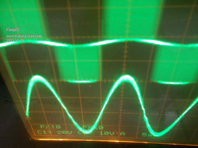 Slope of Sinewave and Choke drive zoomed in. 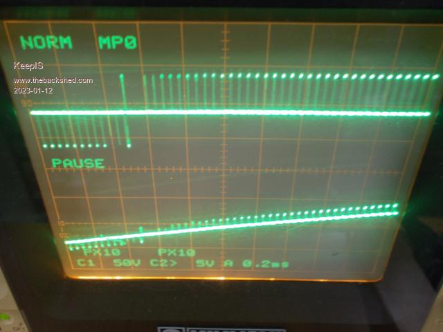 Choke IN and Out overlayed. 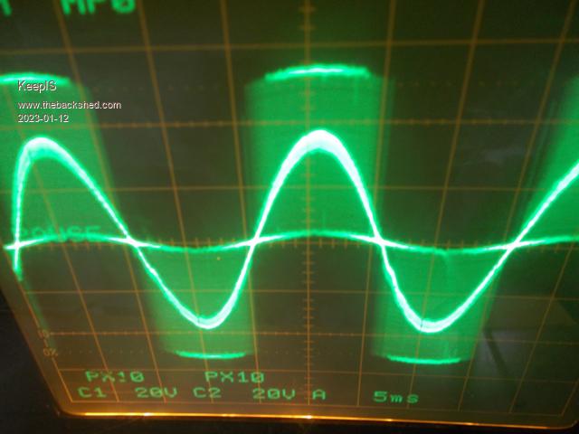 � AC out overlayed. 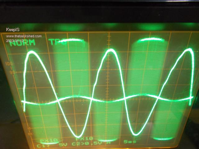 Edited 2023-01-12 18:19 by KeepIS NANO Inverter: Full download - Only Hex Ver 8.1Ks |
||||
| poida Guru Joined: 02/02/2017 Location: AustraliaPosts: 1432 |
 is about as good as it gets. The nature of the PWM modulation means at zero crossing, there MUST be a short pulse at some time just before or shortly after zero crossing. And this excites 1kHz or so oscillations and we see this as wobbles in the waveform. We could attempt to dampen them with an RC filter or something but no point really. The above waveform would be about 0.2% distortion and this is like 10 or 20x better than commercial inverter or generator advertising specs. But experiment and observe and do it again and again! This is why we do this. To learn and to make an inverter to run the house. I look forward to what next you discover. wronger than a phone book full of wrong phone numbers |
||||
| KeepIS Guru Joined: 13/10/2014 Location: AustraliaPosts: 1877 |
 Thanks. Thanks.NANO Inverter: Full download - Only Hex Ver 8.1Ks |
||||
| KeepIS Guru Joined: 13/10/2014 Location: AustraliaPosts: 1877 |
Hi, first and apology: Somehow I missed your earlier post - don't know how????? This is my play/test setup to get ready for testing my own build based on Wiseguys design with his latest revised EG8010 driver. I'm trying not to destroy the test unit but, whatever, so blowing out the cobwebs from ancient memory, and having fun. I had already resonated the toriod secondary to 75Hz. Question: You mentioned re adjusting the resonance after fitting the choke. Wondering how did you did that, I initially used a precision generator and CRO to set the secondary CAP value. I doubt having the choke connected would make that static test for resonance change that much? Current value of Cap is 4uf for 76Hz I was just about to post my test on an E70 N97 core, I will still do that, but it made me wonder about getting a second set to double up and get the inductance higher, shame the postage on them is as much as the dam cores NANO Inverter: Full download - Only Hex Ver 8.1Ks |
||||
| KeepIS Guru Joined: 13/10/2014 Location: AustraliaPosts: 1877 |
As noted above, I missed an earlier post by Poida with some valuable info. Choke Current and Inductance: Cores are E70 N87 Ferrite with 6 turns: I used a wider gap to see how much difference the gap makes to both values. � � � � � GAP: � �0 � � � � � � � 2.8mm � Inductance: � 160uH � � 10.2uH � Saturation: � �20A � � �� �220A As I posted yesterday, the Choke at 10.2uh still bought the idle current down from 1.5A to 320ma [16 watts] but obviously more noise on the choke output. � Simple Saturation Tester 50mv = 200A: 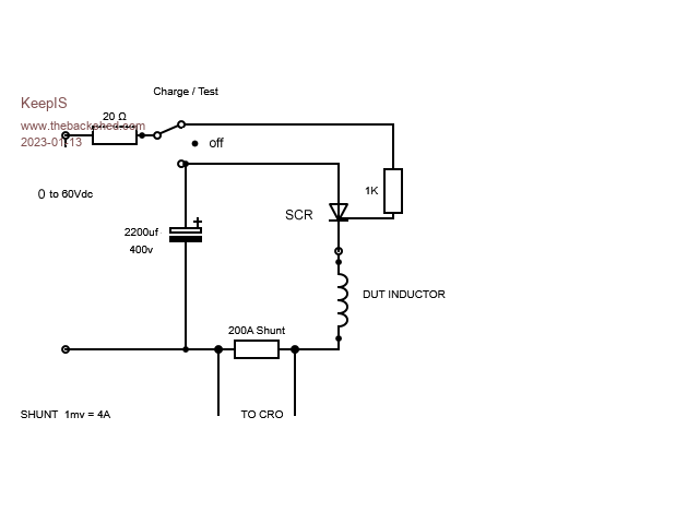 No core Gap: 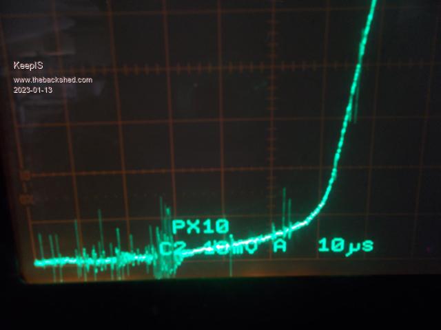 2.8mm core gap: 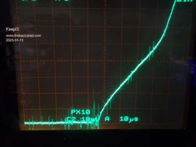 1.3mm core gap: 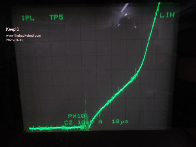 Interestingly halving the gap to 1.3mm made the inductance go up slightly from 10.2uH to 13uH and the saturation drop from 220A to 160A, 80A less. Edited 2023-01-13 11:26 by KeepIS NANO Inverter: Full download - Only Hex Ver 8.1Ks |
||||
| KeepIS Guru Joined: 13/10/2014 Location: AustraliaPosts: 1877 |
Well, I checked the transformer again, it was now 47Hz with the cap supplied with the inverter board, it was previously 76Hz. I'm aware of the remanence in the transformer raised by wiseguy, I did what he did with the generator and series resistor to reset it just in case. And I too needed only 1uf now to resonate it at 75hz, not 4uf which previously resonated it at 76Hz. I'm trying to remember if I checked the resonance BEFORE I had wound the test secondary, that might explain the difference? So with just the 15uH choke, was 13uH in last post but I managed to fit one more turn, so 15uH choke gave me a perfect wave shape but with a tiny amount of HF switching noise, like a tiny staircase effect, idle current was 300ma. With the other 40uH choke added in series, extremely clean waveform with only that slight flickering on the TRAILING slope just after the crossover. � However the idle current is now down to only 200ma, 11 watts? �   EDIT: With the smaller CAP the big variac no longer makes any noise when running loaded or unloaded, but the choke and transformer now make a very faint hum  Edited 2023-01-13 16:15 by KeepIS NANO Inverter: Full download - Only Hex Ver 8.1Ks |
||||
| KeepIS Guru Joined: 13/10/2014 Location: AustraliaPosts: 1877 |
I have two 3 stack blue toriod formers removed from some old solar inverter. The number is MS-226060-2 some reference to "Super MSS" ? Ferrite toriod. � I wound 6 turns of heavy cable through the 3 cores and the measured inductance was 20uH, when I measured the saturation I initially thought the Test rig was causing noise and glitches to show up. Rebuilt the inductance test with no cables except for the choke under test. The induction into the Scope coax lead was still causing the waveform to be modified, but most of the noise had gone, using a quality thick coax lead and adapter soldered straight to the current shunt reference pickup points fixed that. The saturation curve is strange in its slope, like no knee just a gentle curve, in both cases of the E-Core V this blue thing, the E-Core gets to around 180A and then changes quickly, the Blue Cores get to 200A and then seem to saturate very slowly after that? The picture below is 200A per division, the CAP was charged to 90 volts. It's almost as big as the E-Core and it weighs more. Thoughts? Am I seeing things. NOTE : The E-Core has a 1.3mm air gap, without that it saturates at around 60A on this Jig. Blue toriod choke 200A per division. 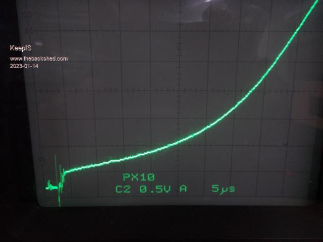 The E-Core on same settings. 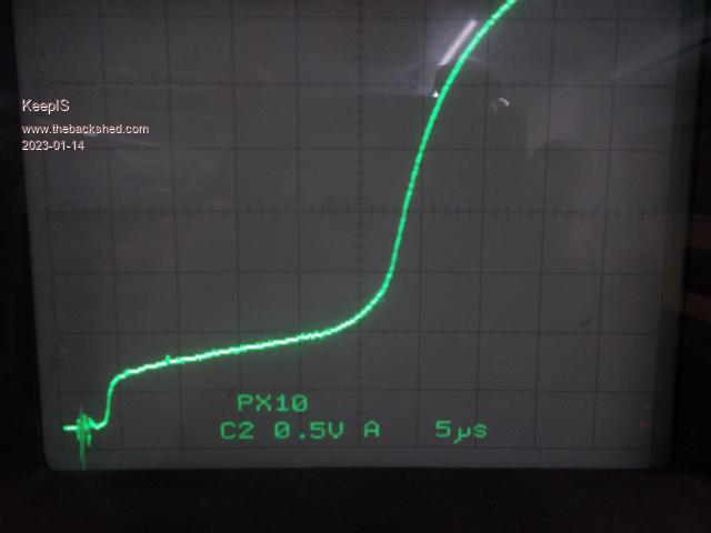 Test Jig:  . Edited 2023-01-14 14:43 by KeepIS NANO Inverter: Full download - Only Hex Ver 8.1Ks |
||||
| Solar Mike Guru Joined: 08/02/2015 Location: New ZealandPosts: 1162 |
Those powdered iron cores make excellent chokes, they are not that expensive, the saturation curve is gradual unlike ferrite, having a large center hole also allows more turns of thick wire. AliExpress Supplier , last item in the list. Cheers Mike |
||||
| The Back Shed's forum code is written, and hosted, in Australia. | © JAQ Software 2025 |
