
|
|
Forum Index : Electronics : Bryan's 150V 45 A MTTP
| Page 1 of 6 |
|||||
| Author | Message | ||||
Bryan1 Guru Joined: 22/02/2006 Location: AustraliaPosts: 2138 |
G'Day Guy's, Well my first MTTP is starting to come together and yesterday found a suitable box for it. One corner was cracked so I epoxied it up. 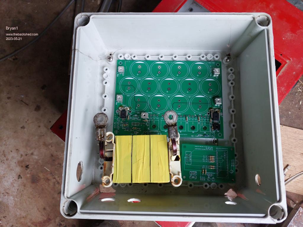 I need to make some 55mm risers for the choke so it can be mounted, also marked out the M3 holes for the fets. 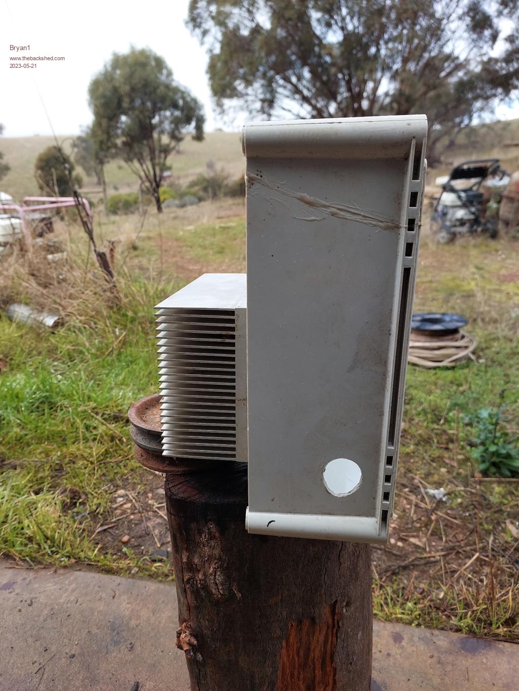 I used the heatsink from that Frontuis grid tie that got a swim and cut hole to mount the heatsink 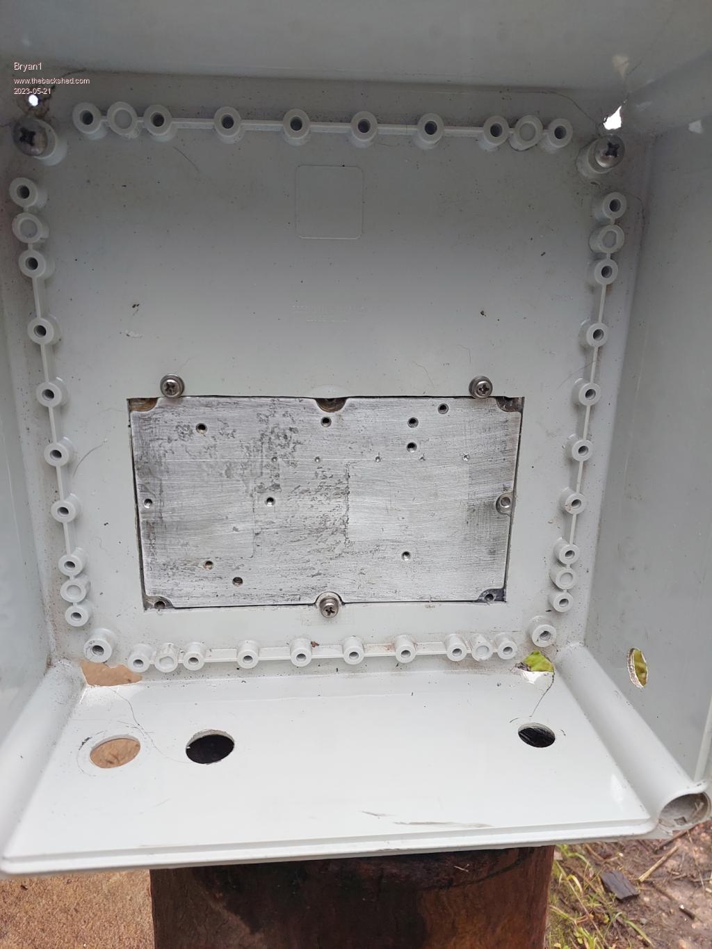 Now for testing this first MTTP will be used on my new PV array, I'll wire 2 panels up in series to get the input voltage up to around 80 volts. Once it's all tested and working it will become the backup MTTP for our 20 year old kanneka panel that have an open voltage around 90 volts and the best output I have seen is around 25 amps and they are lucky to output 3Kw a day. Then I can free up our Outback FM60 for a new house array. Now I do have these BUZ341 fets Mike gave me 200V 33amp with a 0,07RDS to use which I do know will be working on the upper limits but eh I'm still yet to join the blown fet club  so may have to just use them and get told 'I told you so' so may have to just use them and get told 'I told you so'Cheers Bryan |
||||
Revlac Guru Joined: 31/12/2016 Location: AustraliaPosts: 1282 |
Its good to have a little room (while mounted in the box) to plug in the USB cable when making changing settings on the Nano.  Cheers Aaron Off The Grid |
||||
| Bryan1 Guru Joined: 22/02/2006 Location: AustraliaPosts: 2138 |
G'Day Guy's, Well getting closer on this project, with that package from PD the brain board is finished bar that 5K resistor  The MTTP board is just missing the R1212 and the 10 pin connector and no fets or caps have been added yet as I do want to ensure everything is right. Got onto Altronics online to get the rest of bits and with the TIP41C and the TIP35 on backorder I had to take them off to get the rest of the stuff. Also decided on using those big fets I got out of that grid tie as I did have 5 of them here So hopefully the order will co-inside with the arrival of Disco's package with the LCD and backpack then one step closer. Cheers Bryan Edited 2023-05-24 17:40 by Bryan1 |
||||
| pd-- Senior Member Joined: 11/12/2020 Location: AustraliaPosts: 122 |
Just use a 5.6k or 4.7k resister , a 5k resister is as rare as hens teeth. its just there to make shore that the input to the photo diode in the TLP-250 is held below 0.8v in the off state. |
||||
| Bryan1 Guru Joined: 22/02/2006 Location: AustraliaPosts: 2138 |
G'Day Guy's, That package from Gerry turned up this morning so inbetween rain may just get a chance have some soldering fun. That order from Altronics is due tomorrow and gotta say 3 days from Perth to SA aint bad. So this weekend my MTTP will come to life but in order to finish I still need that RS1212 chip and a source to find one. Cheers Bryan |
||||
renewableMark Guru Joined: 09/12/2017 Location: AustraliaPosts: 1679 |
Do you mean this part Cheers Caveman Mark Off grid eastern Melb |
||||
| Bryan1 Guru Joined: 22/02/2006 Location: AustraliaPosts: 2138 |
Well at first I was scared by the shipping with digikey and man $40 for one chip just aint right so went back for another look and $60 free shipping So grabbed the 10,000uf caps and the TIP42C-TIP35 and the R13-1212S chip.So now waiting for the altronics gear to arrive tomorrow and hopefully digikey aint another slow boat. Edited 2023-05-25 17:20 by Bryan1 |
||||
| Bryan1 Guru Joined: 22/02/2006 Location: AustraliaPosts: 2138 |
G'day Guy's, Well got the LCD backboard all built also the MTTP board done as far as I could with what I had here and it does look like the MTTP arduino file I used has a bug or 3  Now when I have the usb connected to the nano on the LCD 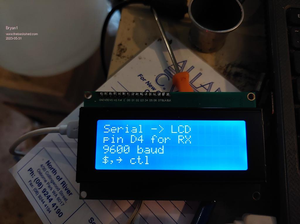 I also uploaded the MTTP file and this is the faults the arduino IDE came up with after uploading the file 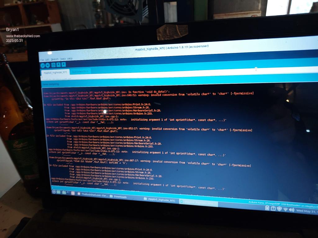 When the brainboard is connected to the MTTP board and with 12volts supplied the LCD stays blank with the nano on the LCD not showing power. Cheers Bryan Edit: So I found the problem was on the LCD backpack why the power wasn't getting turned on when it was all assembled and it was my soldering I reckon as this is the first time I've soldered such small pads on a pcb and looks like I can join the bricked nano club  as the nano on the lcd backpack is a goner. Atleast the lcd survied by the looks. as the nano on the lcd backpack is a goner. Atleast the lcd survied by the looks.In the morning I'll make my own lcd back board and I'll get on and look for another MTTP ino file as I did try both the tempco and the highside NTC getting the same errors on both. Edited 2023-05-31 17:40 by Bryan1 |
||||
| poida Guru Joined: 02/02/2017 Location: AustraliaPosts: 1480 |
bad luck with the soldering You could do it in stages: - load a mppt firmware - do not bother with any LCD connection yet - connect to that nano on the brainbord (either at 9600 or 112500) and configure it to your needs. The mppt will work fine with or without the LCD and the serial connection that is made to it. wronger than a phone book full of wrong phone numbers |
||||
| Bryan1 Guru Joined: 22/02/2006 Location: AustraliaPosts: 2138 |
G'Day Guy's, Well the digikey package turned up today  so now I have everything to get this MTTP done. so now I have everything to get this MTTP done.Now to my surprise this morning I got kicked out of the bricked nano club as the LCD was working.so soldered on the RS1312-12 chip, now I uploaded the new firmware that shows the weekly totals and got the same errors as before when doing a verify, so I uploaded the file again and this is what showed. 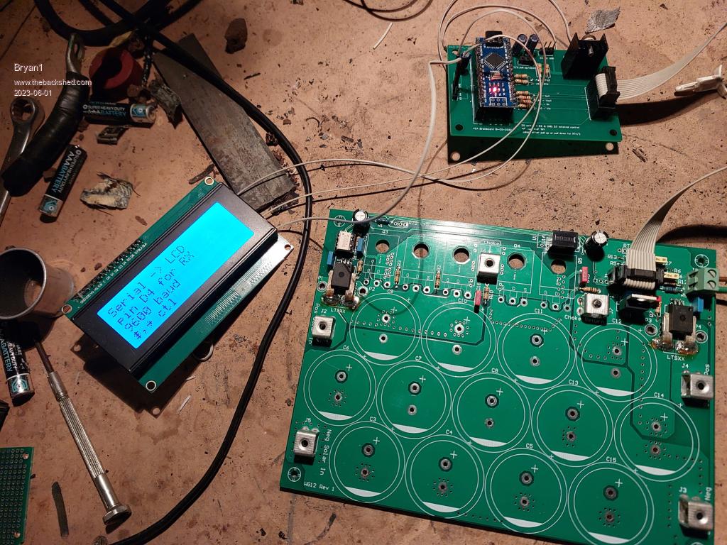 So it does look like the MTTP firmware didn't load, now that 4 pin out on the left of the board I assume is for the serial lcd but it labeled as gnd-+5V-A4-A5 where the lcd is saying D4 is the connection so something is a miss here Cheers Bryan Edited 2023-06-01 11:15 by Bryan1 |
||||
| Bryan1 Guru Joined: 22/02/2006 Location: AustraliaPosts: 2138 |
G'Day Guy's, Well gave up on the LCD after I downloaded the new Arduino IDE and found the MTTP file uploaded and verified fine where the LCD was sill showing the same with no serial commands getting thru.So got on and finished the main board now I did decide to check those fets I got off that grid tie and lucky I did as they are IGBT's 300 volt 70 ones. So the BUZ341's went in and I used all those 1000uf caps where the last one on the input side is a 400 volt 470uf, the output caps are 750uf which came off that grid tie I got from the river. 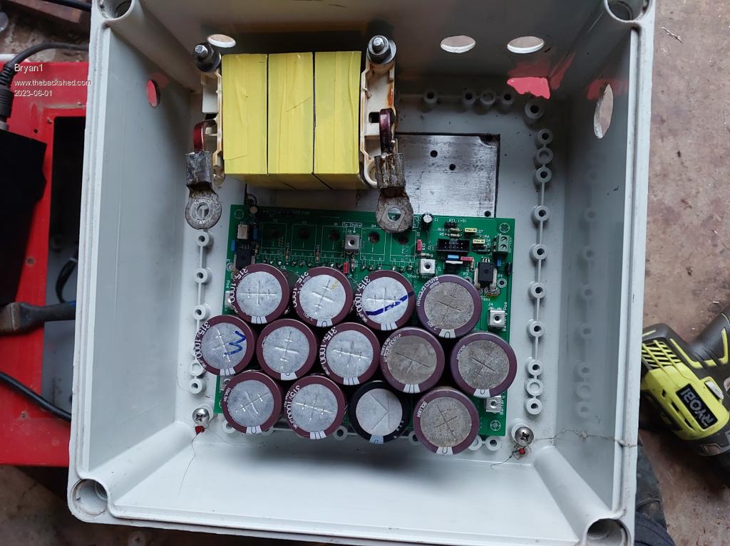 The choke is mounted and for the connection to the board I'm going to use that 6.5x5mm wire and hammer down the ends for the connections. So first job in the morning is to wire up a new LCD and connect it up to my shed solar for testing. Cheers Bryan |
||||
| Murphy's friend Guru Joined: 04/10/2019 Location: AustraliaPosts: 678 |
That might not be a good idea Bryan. In my unit that choke gets quite hot (I have a little fan blowing on it) and your 6.5x5mm copper is quite stiff so you are putting much stress on the connection to the PCB. I would use short flexible cable links to connect that choke to the PCB. |
||||
| Bryan1 Guru Joined: 22/02/2006 Location: AustraliaPosts: 2138 |
Thanks mate and duly noted I do have plenty of off cuts of wire to use so I will go that route.Even with me working in the shed all this week on checking the sg of my forklift battery it's pretty well charged so this will be a good test for for the unit with absorb etc. Cheers Bryan Edited 2023-06-01 18:27 by Bryan1 |
||||
| Solar Mike Guru Joined: 08/02/2015 Location: New ZealandPosts: 1228 |
Regarding that square copper wire 6.5 x 5mm, volume surface area is 32.5mm^2 However at the 20 odd Khz of your PWM signal, due to skin effect the actual effective volume used for passing current is only 12mm^2. Current will only flow in the outer 0.5mm surface, not the whole wire volume. So most of that copper is wasted; you will get a much more efficient choke using multiple insulated strands of 1mm thick wire in parallel, where all the volume of each strand is used for passing current. It will also be much easier to wind. Cheers Mike |
||||
| mab1 Senior Member Joined: 10/02/2015 Location: United KingdomPosts: 282 |
That had me scratching my head too, but the pin labelled A4 on the brainboard is the serial out that goes to D4 on the LCDs nano - at least that worked for me. :) Edited 2023-06-01 20:04 by mab1 |
||||
| Bryan1 Guru Joined: 22/02/2006 Location: AustraliaPosts: 2138 |
G'Day Guy's, Well don't we love these Chinese LCD's Wired it all up today and programmed in the serial LCD and instead of the normal screen it came out in ching worked for about 30 seconds then died. anyway here is the wiring 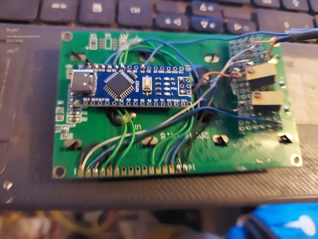 Now on the other side the writing for each pin is on the other side of the board so it does look like a Monday one. Anyway when I get down to the house I'm getting onto the seller to demand a new order of working ones at their expense Edited 2023-06-02 16:50 by Bryan1 |
||||
| Bryan1 Guru Joined: 22/02/2006 Location: AustraliaPosts: 2138 |
G'Day Guy's, Well this doing my head in brandnew LCD 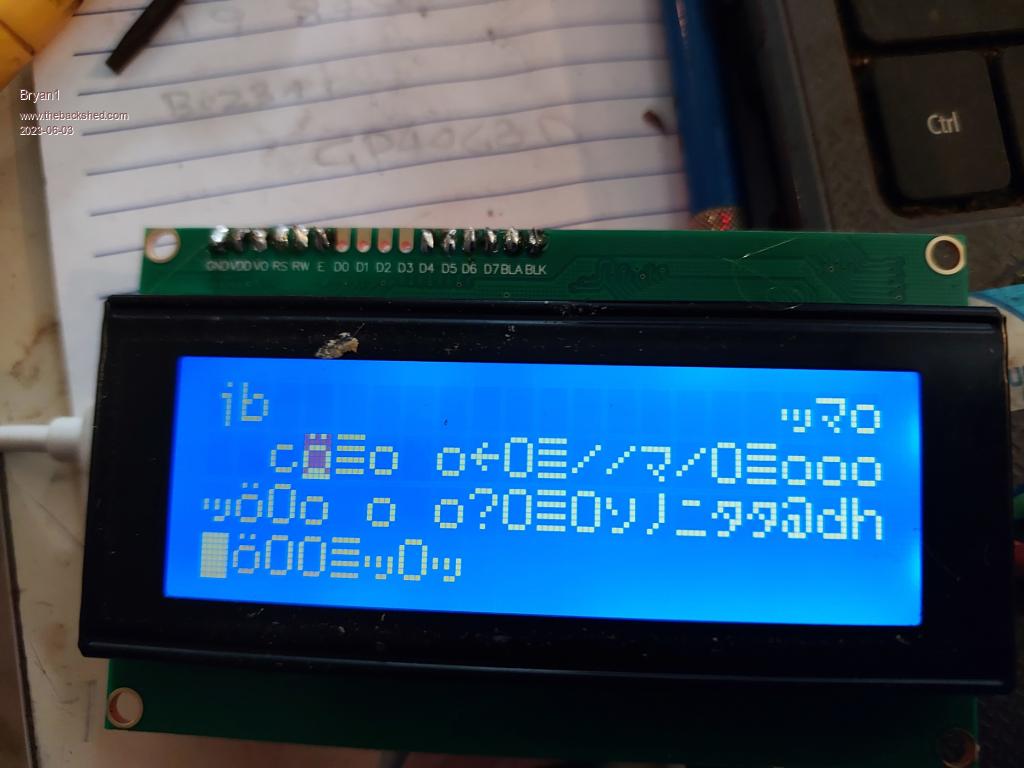 This is the same as I had yesterday before the LCD decided to bit the dust so if anyone can chime in and tell me what the F is going on as this is driving one to call the yard arm. Cheers Bryan |
||||
| InPhase Senior Member Joined: 15/12/2020 Location: United StatesPosts: 178 |
Try using shielded wires for the data lines, or twisted pair, or a ferrite bead. |
||||
| Bryan1 Guru Joined: 22/02/2006 Location: AustraliaPosts: 2138 |
INphase this screen came up straight after uploading the file to the nano and for all the data lines I used single strand cat6E single strand wire. So came down to my house computer only to find the arduino ide wouldn't give me permission to use the usb and wouldn't accept my root password to open as administrator so using my daughters old laptop with winsucucks10 on it to re upload all the files and see if it was linux and that new 2.1 arduino ide. Didn't have this problem with that lcd Gerry sent me as shown in pic's above so all this gobbly gook on the screen is enough to drive one around the bend but my homebrew beer is saving the day. Now just a word about using old second caps to trial it out I connected everything up and yes the screen was the same then I heard a loud bang as that cap beside the fet driver chip which was a secondhand cap decided it didn't want a new life. So replaced with a new cap I found and no other damage was done. Cheers Bryan Edited 2023-06-03 16:01 by Bryan1 |
||||
disco4now Guru Joined: 18/12/2014 Location: AustraliaPosts: 1130 |
Its a bit hard to see, but can you confirm those two blue and two green wires are going to D7,D8,D9 and D10 on the nano. One wire on each and they respectively go to D7,D6,D5 and D4 on the LCD. The LCD has several character sets so any reversal of these wires would likely print the wrong characters and not all English. F4 H7FotSF4xGT |
||||
| Page 1 of 6 |
|||||
| The Back Shed's forum code is written, and hosted, in Australia. | © JAQ Software 2026 |
