
|
|
Forum Index : Electronics : Bryan's 150V 45 A MTTP
| Author | Message | ||||
Bryan1 Guru Joined: 22/02/2006 Location: AustraliaPosts: 1211 |
Ah ok I did put D10 on pin 14 and went down from there so do I have it all backwards ??? If so that would be the problem if so I'll reverse the wires in the morning and connect it all up for testing. It has been well over a decade since I did electronics and the grey matter does need a reality check me thinks but eh thats all the fun aint it. Cheers Bryan Edited 2023-06-03 16:55 by Bryan1 |
||||
| Bryan1 Guru Joined: 22/02/2006 Location: AustraliaPosts: 1211 |
Also with D2 and D3 on the board it says EQ now with the lastest code for the weekly totals is D2 normally pulled high and if so a simply switch can be used to pull D2 low for the weekly totals if my thinking is straight. also got that kit of parts for the LC meter yesterday so thats a job for the morning after I sort out this MTTP Edited 2023-06-03 17:26 by Bryan1 |
||||
| mab1 Senior Member Joined: 10/02/2015 Location: United KingdomPosts: 166 |
If you've connected the digital pins differently to poidas original circuit you can change their assignments in the piggyback lcd program to match instead of resoldering the wires. If that's easier. But yes if you're getting foreign characters it suggests a communication error between the piggyback nano and the lcd during initial setup. |
||||
| Bryan1 Guru Joined: 22/02/2006 Location: AustraliaPosts: 1211 |
G'Day Guy's, Well it was the grey matter and after a few longnecks just had to come up to the shed. 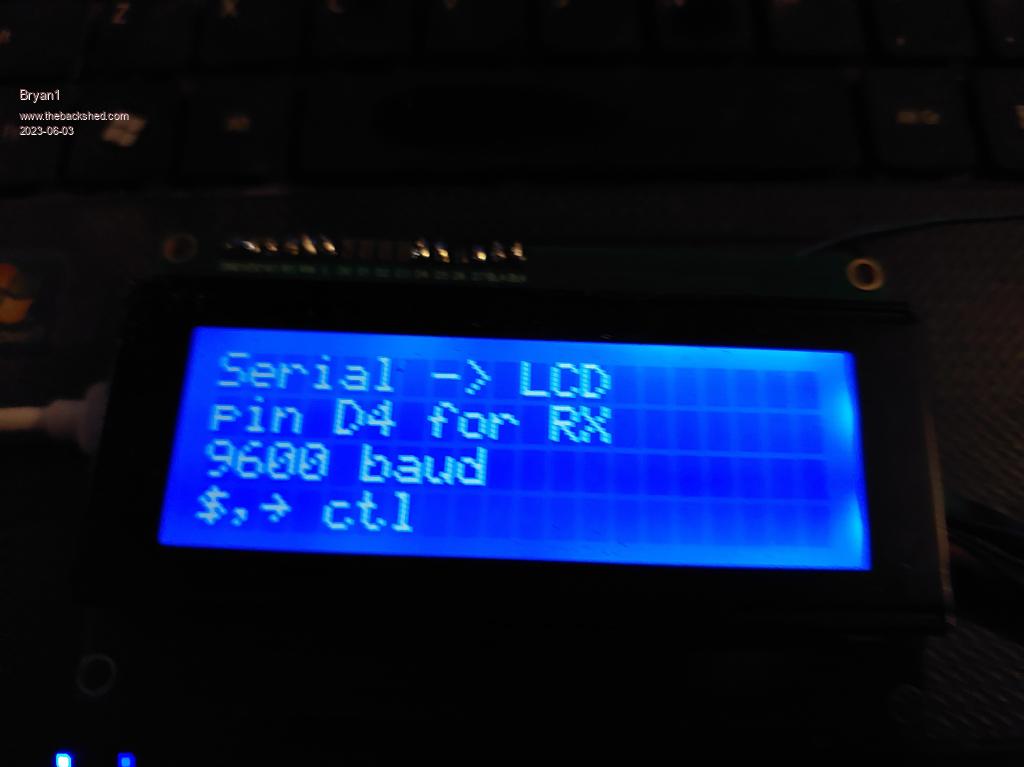 Now for the choke connections I found those short cables off the aerosharp chokes fitted nicely so used 2 on each leg and used some of the M4 socket head cap screws I bought the other day. So in the morning this MTTP will become live and for the 12 volts I'll run a cable from my shed radio array that has been going 20 years and will supply a solid 12 volts. Then onto my inverter project with only a few more bit to buy. Cheers Bryan |
||||
| Bryan1 Guru Joined: 22/02/2006 Location: AustraliaPosts: 1211 |
Ran out of time this arvo to get it installed and with the rain I thought it best to leave it for for the morning. Now it is basically all finished so hopefully once installed it will work as it should. Cheers Bryan Edited 2023-06-04 18:05 by Bryan1 |
||||
| Bryan1 Guru Joined: 22/02/2006 Location: AustraliaPosts: 1211 |
G'Day Guy's, Well got the MTTP all setup today and looks like some fault finding to as this is the lcd output 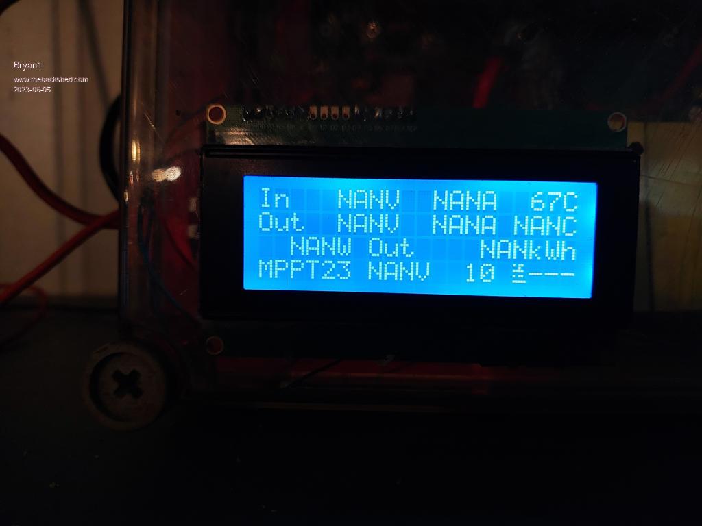 So some help is needed here as why the volts etc isn't showing Cheers Bryan |
||||
| poida Guru Joined: 02/02/2017 Location: AustraliaPosts: 1389 |
I think it's time to calibrate your mppt connect to the nano via the usb socket with the laptop It might be 9600 baud (or it could be 115200 baud.) but try 9600 first use the Arduino program to connect to the serial device. send ? to it (then ENTER) you should get a menu FIRST YOU NEED TO GET THE MENU BEFORE YOU CAN CONTINUE send Z to set some defaults. do this first. Once you tell the mppt what voltages are what, and zero the current sensors and then calibrate the current sensors you will get it working. how I do it: get your multimeter, send ? and then measure the input voltage with the DMM send C to the mppt and it will say "what DC volts IN is this?" tell it what it is same for the battery or mppt OUT terminals. measure that and then send D to the mppt which will ask "what volts is this on the output". tell it that. Now you need to be able to measure current. I use a cheap UNI-T DC clamp meter but there are other ways to do this. Disconnect the solar INPUT. We do not want 100V DC when we play with things. Disconnect the mppt OUTPUT (or battery, same thing) We do not want 1000 Amps potentially giving us nice surprises. Get a current source. I use a bench power supply. It gives me 6 Amps even when connected to a short circuit. You can make one. 12V car battery, 60W headlight globe. this will be about 5 Amps. power mppt up with 12 supply. Have nothing connected to input terminals AND nothing on output terminals. from the menu, send G to tell the program what zero amps is for the INPUT. it will think for a bit. And then print the menu again. Send H to tell it what zero output amps is. Again a think and then the menu again. Now apply a known current across the input sensor. Positive of the current source goes on the SOLAR + terminal. negative/ground goes to ground. Send E and tell it what that Amps is. Now we have input current sensor calibrated. apply current source to output current sensor. Put the wires on the sensor terminals for best effect. Again you need to put the current through the sensor in the correct direction. Send F to tell it what this current is. Now we have both current sensors calibrated AND the two voltages. Zero the energy total, so send N for that. Set up the charge voltages as needed. To have no battery tempco, just make BV tempco = 0.0 Try to avoid leaving anything as NAN I like a 6 hour absorb time, I set float the same as absorb. I do not bother with equalise We can finish this once you get a menu and can get a few things calibrated. Edited 2023-06-05 21:24 by poida wronger than a phone book full of wrong phone numbers |
||||
| poida Guru Joined: 02/02/2017 Location: AustraliaPosts: 1389 |
I wrote "Now apply a known current across the input sensor. Positive of the current source goes on the SOLAR + terminal. negative/ground goes to ground." this is wrong, you need to apply the current across the sensor terminals directly. There is no direct connection from SOLAR - or ground to the negative terminal of a sensor. wronger than a phone book full of wrong phone numbers |
||||
| Bryan1 Guru Joined: 22/02/2006 Location: AustraliaPosts: 1211 |
Thanks for that Poida I just went thru and did all the calibration but for some reason it won't come out of nite mode and I have set Y to 0. The solar is still going thru the board to the batteries so the nite mode should see there is power going thru. 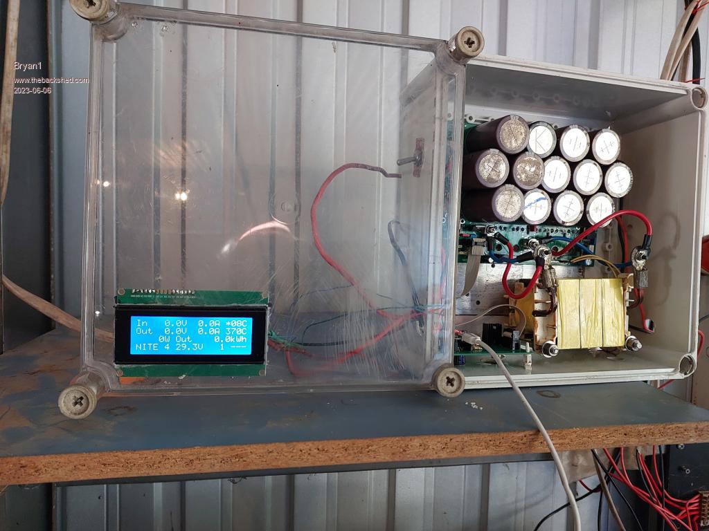 So the sleuthing goes on Cheers Bryan Edited 2023-06-06 10:55 by Bryan1 |
||||
| poida Guru Joined: 02/02/2017 Location: AustraliaPosts: 1389 |
If the above photo has both the solar input connected and the battery connected then zero Volts IN is not good. It must show what it is from a DMM reading zero volts OUT is also not good. It must show the battery voltage. One reason it can not get to mppt or absorb mode is when Vout is greater than Vin this is during night time, the panels make only a few volts.. In the case of a correctly running mppt at night, and a battery voltage of 50V we will see something like 49V on the Input and 50V on the output. The 1 Volt difference is due to the voltage drop through the FET's body diodes. wronger than a phone book full of wrong phone numbers |
||||
| Bryan1 Guru Joined: 22/02/2006 Location: AustraliaPosts: 1211 |
Just got back from town and there was no change so I uploaded the highside_ntc code as the that latest code for the weekly totals kept doing the same thing. When I use C and then D the output is inf( nan V ) for both and this is with the unit not connected at all. So don't really know why the code won't accept my input Cheers Bryan |
||||
| poida Guru Joined: 02/02/2017 Location: AustraliaPosts: 1389 |
so you do this without a voltage applied to the terminals? Do I understand correctly? I want us to calibrate the voltages first, with some known or measured voltage on those terminals. Then remove them to calibrate the current sensors. We do both zero current and then a known current. wronger than a phone book full of wrong phone numbers |
||||
| Bryan1 Guru Joined: 22/02/2006 Location: AustraliaPosts: 1211 |
Poida when I first tried all connections were in place and it made no difference so I removed the connections at the external ends as it much easier access and got the same result. In the morning I will try again but there is one thing I only have one temp probe connected going to the heatsink and the other with no connection and the temps shown are totally off the map. Now the LCD keeps shown overtemp and when I put U to 1 it showed overcurrent yet 0 current was showing on the LCD. I connected RT2 with the sensor and on the lcd it showed *68C when the heatsink is cool to touch and the other sensor reading was showing over 200C. Whether this is causing my troubles I don't know but it is alarming to see just how far out there are. |
||||
| poida Guru Joined: 02/02/2017 Location: AustraliaPosts: 1389 |
one thing to look at please Bryan the link between logic and control ground and noisy ground. This must be made. If it's not there, we get the things that are happening. See the Green line? 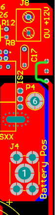 Wiseguy designed this with the intention of having a ferrite bead on the link to help reduce the noise on the analog inputs into the nano. In testing I found no improvement. No link will give us the sort of results we are seeing now. wronger than a phone book full of wrong phone numbers |
||||
| Bryan1 Guru Joined: 22/02/2006 Location: AustraliaPosts: 1211 |
Hi poida yes I have made that link and in the gear pd- sent me was 3 small ferrite beads so I did fit one to that connection. Now yesterday I did use my Fluke scope meter to look at some of the connections and the ACS754 current sensors had 4.95V GND and 2.5V on both of the sensors, the 3 fets weren't turned on at all and the 2 diodes were showing -25.85 volts in respect to ground. got a few jobs to do this morning then I'll get back to try and get this sorted. now with the temp sensors playing havoc with my setup would be a good idea to comment out the temp commands in the code so they don't play apart in the configuration then un-comment when it's all setup. Cheers Bryan |
||||
Revlac Guru Joined: 31/12/2016 Location: AustraliaPosts: 961 |
Bryan, you could have a look at the menu Here if you haven't already it may help, The temp sensors RT1 and RT2, I have them to 5v on the main board and RT pull down on the nano board, in the menu option 3 is 1 for 5v, Temperature ended up about right for me. I don't think the temp sensors is causing any issue, If this is of any help. Please follow poida's instructions above to calibrate. Edited 2023-06-07 09:06 by Revlac Cheers Aaron Off The Grid |
||||
| Bryan1 Guru Joined: 22/02/2006 Location: AustraliaPosts: 1211 |
Ok decided to load the latest code and setup the serial connection and typed Z in to get the defaults 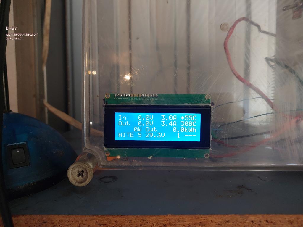 Measured the input volts 25.42 so typed C and entered it, measured the output volts 24.9 so typed D and entered it. 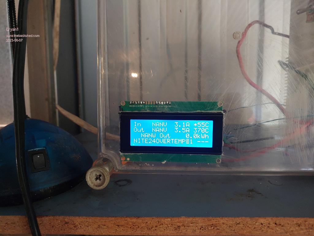 So now i'm at a loss why it won't accept my input figures Cheers Bryan |
||||
| pd-- Senior Member Joined: 11/12/2020 Location: AustraliaPosts: 122 |
Aaron is onto it On the brain board below the two caps in the top center is a header labeled RT1/2 pull up / down you need to jumper the right two pins if you have RT1/2 in the default hols |
||||
| Bryan1 Guru Joined: 22/02/2006 Location: AustraliaPosts: 1211 |
Decided to take the board out of the box so I could test on the shelf and this stuck out like the dogs B's  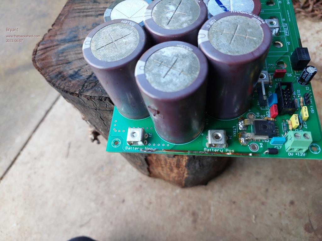 The only way i reckon could of happened was when I was probing I did hit the choke connection and got a spark  So I'll fix the track on the board and test all the caps to ensure they are OK. I got a new 9 volt battery for my clamp meter and did see the input amps were 14 amps and the lcd was showing 9 amps so they will need calibrating again. The fun continues Cheers Bryan |
||||
| Bryan1 Guru Joined: 22/02/2006 Location: AustraliaPosts: 1211 |
G'Day Guy's, Well fixed that broken track with some single core wire and for peace of mind changed out those dirty caps and replaced the 4 for a total of 870uf. 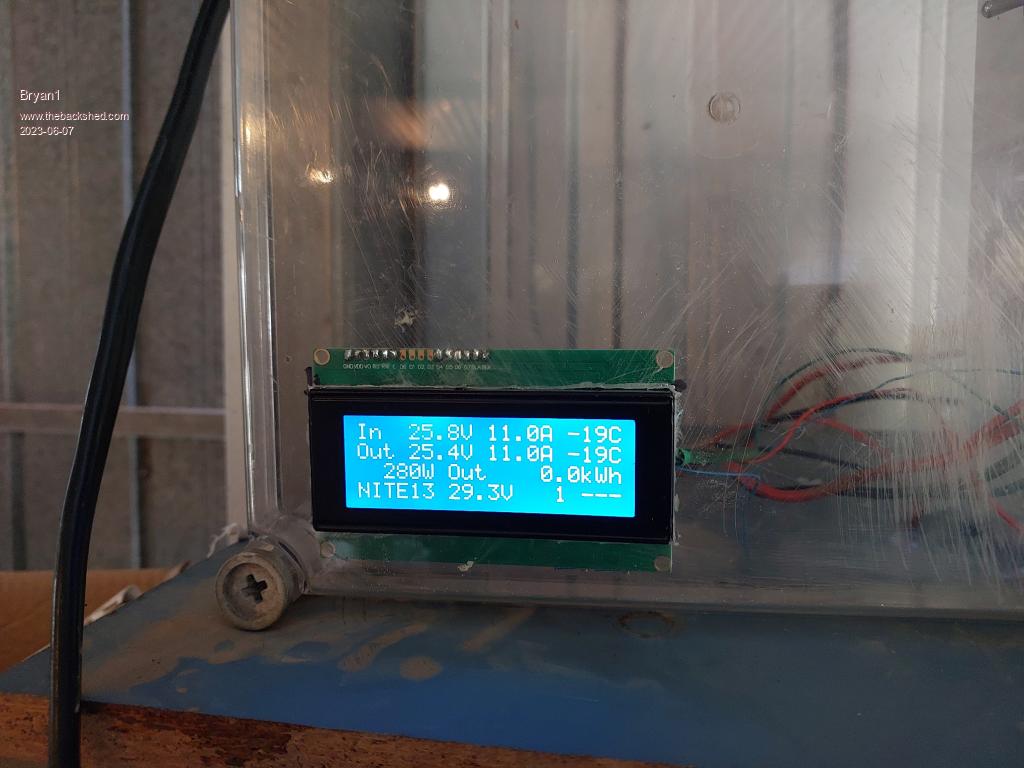 On checking with my current meter the input and output amps are spot on  aswell as the voltages. aswell as the voltages.Now these 190 watt panels have an open circuit of just over 40 volts but the battery looks to be clamping the voltage and my plan is to put 2 in series to double the input voltage and it does look like I'll have to to get it out of nite mode. Cheers Bryan |
||||
