| |
Page 1 of 3   |
| Author |
Message |
mab1
Senior Member

Joined: 10/02/2015
Location: United KingdomPosts: 282 |
| Posted: 10:04pm 21 May 2023 |
 Copy link to clipboard Copy link to clipboard |
 Print this post |
|
Thought I'd add mine as there seems to be a run of these builds developing - and i finally have a bit of progress to show.
As I've never done Arduino before i decided to start there:
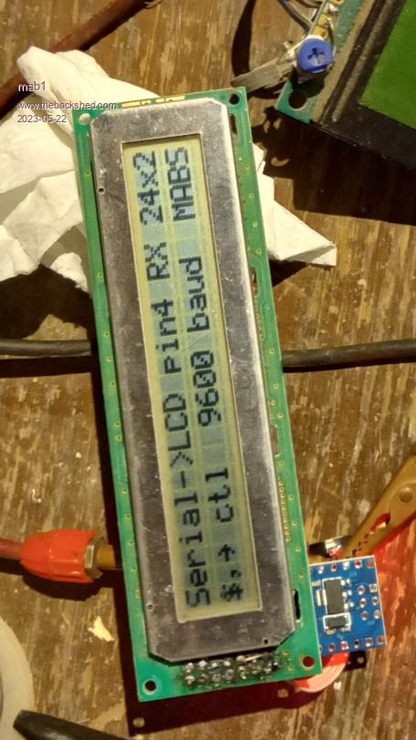
The pic of the 20x4 LCD didn't come out too well, but as i got a job lot of nanos i decided to convert this one too as it'll be a lot easier for a future project especially as it has a confusing 2x7 array of pins instead of the usual 14 or 16 pins in a row.
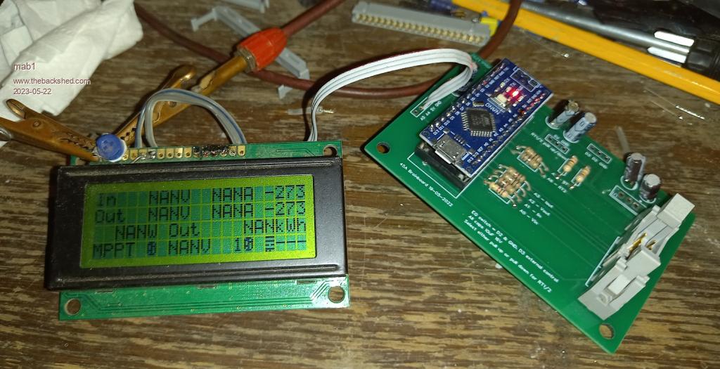
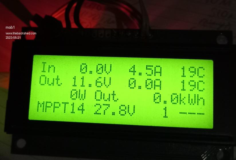
Here's the mppt 20x4 LCD actually receiving data from the mppt nano - although I'm not sure I've got the best version of the mppt code - as I'm moving to liion batteries i don't need absorb/equaliation/float voltages, but then i guess i can set them all the same in the code.
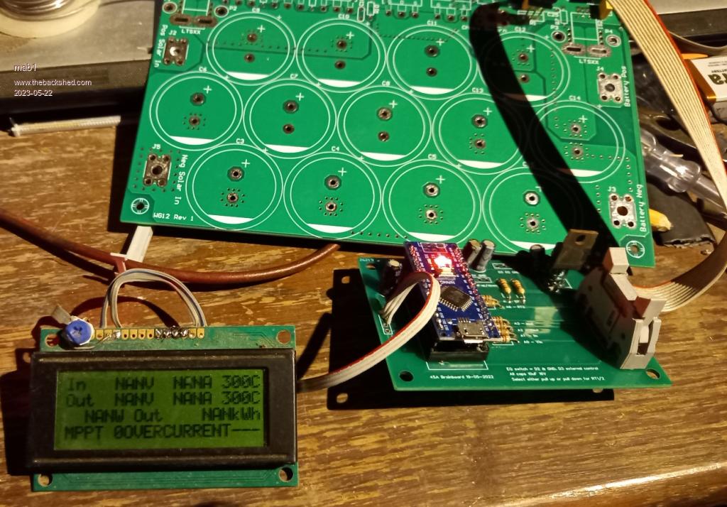
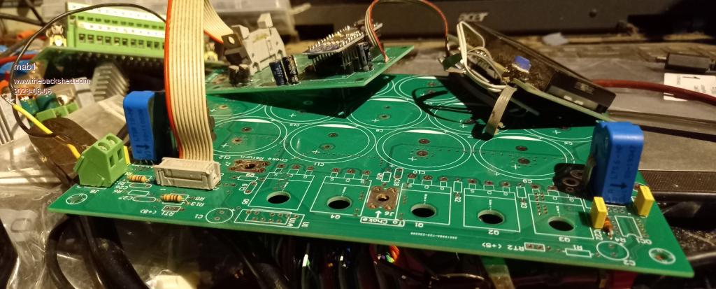
And here's the whole mppt as far as I've got it. I'm currently trying to salvage as may bits as possible from junk pcbs (managed to find two 7805s following my voltagr regulator question on the other thread). I expect to have to buy some bits but I've got an aerosharp inverter, and a santerno inverter both of which have lem current sensors and big caps. Surprisingly with all the junk here I can't find a single 1nF capacitor. |
| |
Bryan1

Guru

Joined: 22/02/2006
Location: AustraliaPosts: 2138 |
| Posted: 10:18pm 21 May 2023 |
Copy link to clipboard |
Print this post |
|
Looking good Mab and eh mate if you need some of those M4 connectors I still have quite a few here and I can throw in some of that yellow tape for insulating the choke cores if you like.
Like you I am short of those small caps, nano connecting pins etc and I still need to source that 12-12 isolating chip.
PM me if want those connectors and tape so you move forward mate.
Cheers Bryan |
| |
poida

Guru
Joined: 02/02/2017
Location: AustraliaPosts: 1480 |
| Posted: 12:36am 22 May 2023 |
Copy link to clipboard |
Print this post |
|
Mab1, great to see all this progress. The size of the heatsink will
let you run it at 45Amps or more if you got the panels and the load.
I am really happy to see the Arduino stuff was no problem too.
Once you've built the boards calibration is the final job to do
and it's not a huge issue. Just do one thing at a time..
wronger than a phone book full of wrong phone numbers |
| |
mab1
Senior Member
Joined: 10/02/2015
Location: United KingdomPosts: 282 |
| Posted: 09:36pm 22 May 2023 |
Copy link to clipboard |
Print this post |
|
Thanks Brian, i do appreciate the offer
, but i suspect the cost of postage to the UK would be prohibitive  . .
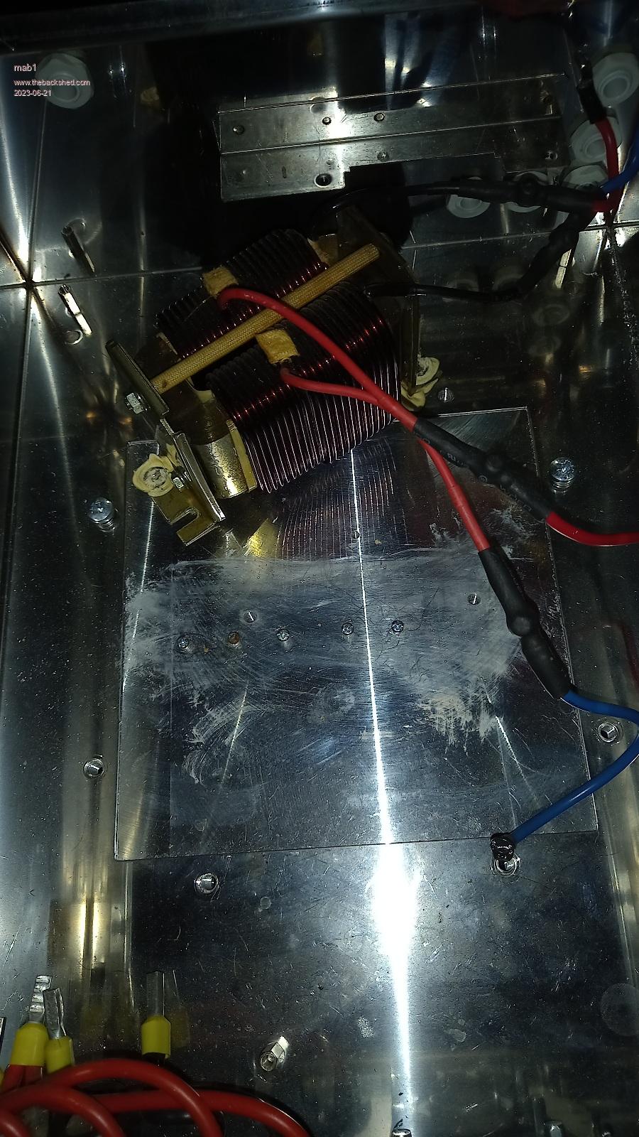
Talk of big heatsinks made me think of the case of the santerno inverter: i originally acquired two of them as donors for an inverter build (3.3kva toroidal transformers), but as long as the powerjack keeps going that project's low priority. Looks like a good home for the mppt, although i might have to grind off the top bit where the toroidal tx and inductor were mounted.
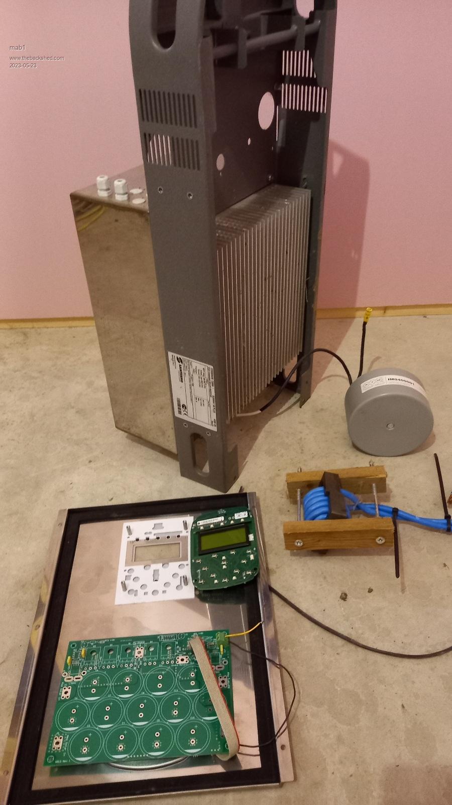
It's a big stainless box with a massive heatsink, with a 20x4 lcd already mounted on the front face (why didn't i think of it before?!)
The round grey thing is a 5mH inductor that was in series with the 180v primary of the transformer, so must have been rated for 18A. Might be worth un-potting and adapting it?
The ferrite Ecore inductor, wound with 11 turns 25mm2 blue wire is one i put together for the inverter build, but then read some more and realised it would saturate at ~40A or so IIRC (about 50uH as is), so it might be more suited to the mppt, but I'm not really ready to think about inductors yet - need to finish the mppt main board first. Only room in my head for one problem at a time
Edited 2023-05-23 07:39 by mab1 |
| |
mab1
Senior Member
Joined: 10/02/2015
Location: United KingdomPosts: 282 |
| Posted: 10:51pm 05 Jun 2023 |
Copy link to clipboard |
Print this post |
|
Not much progess here:
I seem to have killed my LEM current sensors from the aerosharp inverter:  if i understand them correctly they should output vcc/2 with zero current - i.e. 2.5v, but they all output zero volts. if i understand them correctly they should output vcc/2 with zero current - i.e. 2.5v, but they all output zero volts.
Possibly i got them too hot whilst desoldering them - i (belatedly) read the datasheet where it says the primary conductor shouldn't go over 100°C, although, even if i had read it, I'm not sure how I'd've got them off without getting them that warm.
What's really annoying is i managed to do this just after placing an order for all the bits i couldn't scrounge. 
I guess I'll probably order some of the aleggro sensors acs758 or acs756 or something? I've sort of gone off LEM sensors for the moment. |
| |
poida
Guru
Joined: 02/02/2017
Location: AustraliaPosts: 1480 |
| Posted: 08:12am 06 Jun 2023 |
Copy link to clipboard |
Print this post |
|
I don't think you have blown them.
The arrow on the case shows the current flow direction.
positive -->> negative
This direction is not how the current flows in the case
of the mppt design but all will be good
since the firmware can handle negative values for the current sensor calibration.
These sensors are of a type that gives 2.5V out for zero current
and can go negative or positive from that 2.5V
to 0.5V to 4.5V
The specs discus the temperature of the current conductor leads
I have use a hot air gun set to Very Hot to remove them. Had them smoking.
So I expect it to work fine but we need to prove a few things first.
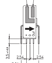
Is there 5V from + pin to 0 pin?
with zero current flowing through it, is there 2.5V on "Out" pin with
0 pin as ground?
Edited 2023-06-06 18:13 by poida
wronger than a phone book full of wrong phone numbers |
| |
poida
Guru
Joined: 02/02/2017
Location: AustraliaPosts: 1480 |
| Posted: 08:31am 06 Jun 2023 |
Copy link to clipboard |
Print this post |
|
the ACS 758 series are good, I've used them.
either the bipolar or unipolar types will work well.
go for the 50 Amp parts, assuming you will not see 50 Amps
on the input and or output.
I've build boards with the 100 Amp bipolar parts and they work fine.
the pinout is what Wiseguy designed for with this board.
5V, pins are +, 0 and Out, just like the LEM sensors and the Allegro sensors expect current to flow from RIGHT to LEFT which means we can use unipolar parts and get better
resolution.
wronger than a phone book full of wrong phone numbers |
| |
mab1
Senior Member
Joined: 10/02/2015
Location: United KingdomPosts: 282 |
| Posted: 01:41pm 06 Jun 2023 |
Copy link to clipboard |
Print this post |
|
Thanks for the optimism Poida, but i've just rechecked and i have got 4.94v on the +pin, 0v on the o pin and just mV on the out pins of all of them ( including the 3rd one from the aerosharp). No shorts between the pins. Two of the three are the LTSR type but I've left the ref pin floating (i think it should float at 2.5v?)
I don't know how I've killed them if not heat - I've never been a static-y person and usually unsolder things fine, but they do seem dead.
Just considering buying cheap from China - they'll take longer to get here but it definitely saves money. |
| |
poida
Guru
Joined: 02/02/2017
Location: AustraliaPosts: 1480 |
| Posted: 10:03pm 06 Jun 2023 |
Copy link to clipboard |
Print this post |
|
one thing to look at please Mab
the link between logic and control ground and noisy ground.
This must be made. If it's not there, we get the things that are happening.
See the Green line?
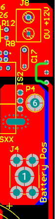
Wiseguy designed this with the intention of having a ferrite bead on the link
to help reduce the noise on the analog inputs into the nano.
In testing I found no improvement.
No link will give us the sort of results we are seeing now.
wronger than a phone book full of wrong phone numbers |
| |
poida
Guru
Joined: 02/02/2017
Location: AustraliaPosts: 1480 |
| Posted: 02:01am 07 Jun 2023 |
Copy link to clipboard |
Print this post |
|
the 4 pin versions drive the output relative to the ref pin
I use one for a current sensor with the inductor testing.
It's so easy to use the output and ref pin since
I put the CRO lead on one and the earth clip on the other
and if the output is inverted I just swap the pins.
I think there is little output between ground and output in the case of the 4 pin versions
wronger than a phone book full of wrong phone numbers |
| |
mab1
Senior Member
Joined: 10/02/2015
Location: United KingdomPosts: 282 |
| Posted: 09:31pm 07 Jun 2023 |
Copy link to clipboard |
Print this post |
|
Hi poida,
Well, I hadn't made that link between the power ground and the logic/control ground, but whilst I'm reluctant to question the advice of The Master, Yoda, , as i haven't fitted any of the power components - caps, fets, diodes - and was powering the board via the 12v input (i.e. no connection to battery or pv inputs), i didn't think the ground link could affect the current sensors.
I have made the link now and added the rest of the passive components on the logic/control side, but still cannot get an output voltage from either LEM.
As for the 4pin type - my reading of the datasheet says they should work like the 3 pin version if the ref pin is left floating, but as a sanity check i did try measuring the voltage between ref and out: still 0.000v with or without 4A running through the primary conductor.
So i have ordered some ACS758s  . I'm still at a loss as to how i killed them all, but even though they draw 18ma at 5v from the supply, i just can't get a voltage from their outputs. The outputs are not shorted, they seem to be open cct. . I'm still at a loss as to how i killed them all, but even though they draw 18ma at 5v from the supply, i just can't get a voltage from their outputs. The outputs are not shorted, they seem to be open cct. |
| |
poida
Guru
Joined: 02/02/2017
Location: AustraliaPosts: 1480 |
| Posted: 01:05am 08 Jun 2023 |
Copy link to clipboard |
Print this post |
|
they draw 18mA? they are dead, sorry to say. Oh well, I thought it worth it we made sure before tossing them in the bin. I agree with your reading of spec sheet.
I was wrong with "output to ground being zero volts"
Edited 2023-06-08 11:19 by poida
wronger than a phone book full of wrong phone numbers |
| |
mab1
Senior Member
Joined: 10/02/2015
Location: United KingdomPosts: 282 |
| Posted: 09:21am 08 Jun 2023 |
Copy link to clipboard |
Print this post |
|
Yes, definitely worth trying  , particularly as buying new's put up the cost of the build , particularly as buying new's put up the cost of the build
I did come up with another theory as to how i might have killed them:
a full explanation would be tedious but the short version is that a badly frayed wire on the weller soldering iron i was using might have connected the tip to 24v a.c. relative to my sticky hands holding the pcb with the lem sensors i was desoldering. |
| |
mab1
Senior Member
Joined: 10/02/2015
Location: United KingdomPosts: 282 |
| Posted: 10:27pm 20 Jun 2023 |
Copy link to clipboard |
Print this post |
|
Creeping along on this project:
I now have working current sensors having bought some unidirectional 50A acs758s.
And have followed Poidas instructions on calibration - although i might redo the amps as i suspect the reference ammeter i used was underreading.
Also realised this lcd has a backlight - but it draws 200mA! Makes the 7805 run hot.
I have drilled & tapped 5 holes in the heatsink for fets & diodes and i do have some of the recommended 150v fets and 200v schottky diodes ( and Fod3182 optos), but am now wondering if i should get some 200v fets as i would quite like to use one of these mppts on a 4-series array with a vmpp of about 140v. Also just realised I'm a bit short on insulation washers for to247  there's so much to think of when making orders. there's so much to think of when making orders.
That's the heatsink with 5 M3 screws and the monster inductor from the aerosharp - still got the whole inductor modding & testing thing to look forward to.  |
| |
pd--
Senior Member
Joined: 11/12/2020
Location: AustraliaPosts: 122 |
| Posted: 08:38am 21 Jun 2023 |
Copy link to clipboard |
Print this post |
|
Looking good
you could go with sumthing like a IRF200P222 but they start to get expensive.
I have a heatsink on the 7805 and now its just worm.
theirs one on the Aerosharp board |
| |
mab1
Senior Member
Joined: 10/02/2015
Location: United KingdomPosts: 282 |
| Posted: 12:59am 23 Jun 2023 |
Copy link to clipboard |
Print this post |
|
Thanks for the fet suggestion - I'm not really clear on how to choose fets other than the obvious volts, amps, rds and "typically used in switchmode psus" on the datasheet .
Yes i should probably put a heatsink on the 7805, although I'm more inclined to put the backlight on a switch/button as, once the unit's up and running i won't be watching it constantly, and 200mA is a significant drain of power. Or if there's a spare pin on the nano i suppose i could get it to turn on the backlight when the battery >= float voltage, if i dare tweak poidas code. |
| |
mab1
Senior Member
Joined: 10/02/2015
Location: United KingdomPosts: 282 |
| Posted: 06:58pm 27 Jul 2023 |
Copy link to clipboard |
Print this post |
|
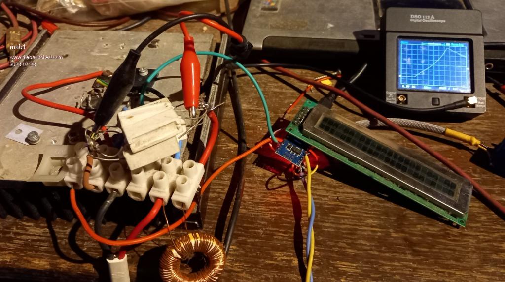
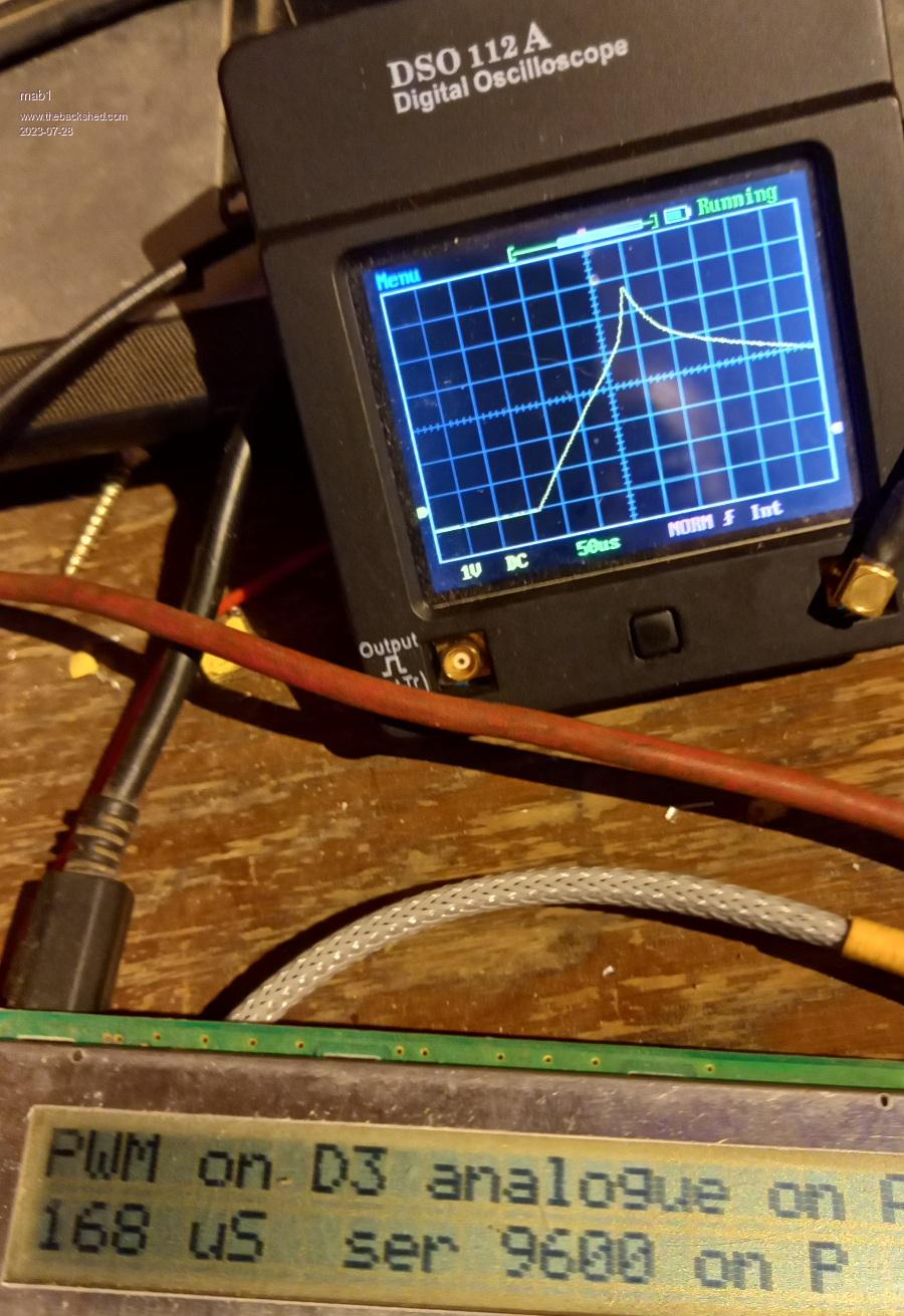
Ok, I've finally started looking at inductors: I've reprogrammed the nano with the 24x2 lcd to do pwm. It works from about 6uS up to 1023uS and runs at about 100Hz to allow the inductor current to fall.
Using an 06CN10L (60v 100A to220) mosfet along with one of the 200v schottkys that will be going into the MPPT unit.
Testing the inductor setup with a little torroidal inductor
Tried my big ferrite that i wound a while ago with 11 turns of 25mm2 . I originally made this with an inverter build in mind, but that was before i learned that it would saturate at too low a current to be useful.
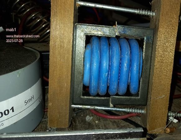
Depending on wether i have 0.5mm or 1mm of cardboard in the gap it's either 55uH and 30A saturation or 42uH and 50A from memory (didn't write it down), but 25mm2 is overkill so I thought if i can get more turns of something smaller in there, and a bigger gap it might work for the MPPT.
I want to run 4 panels in series, vmmp 130v, into a 24v battery. Using this online calculator:
http://schmidt-walter-schaltnetzteile.de/smps_e/abw_smps_e.html
i reckon i need 100uH and that would give me a ripple of 10A at 20kHz.
So, with 24turns of test wire i get these results:
1.5mm gap (three card layers)
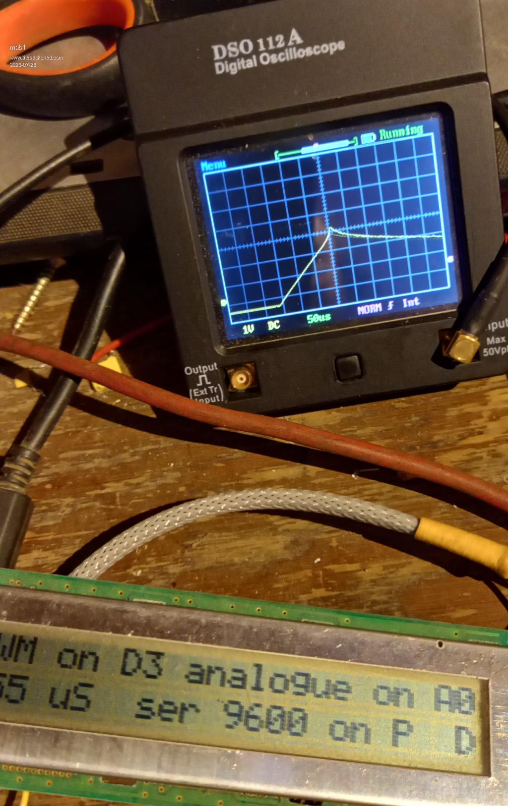
Thats about 30A, and i calculate 145uH (scope reading 'current' using 0.1ohm shunt resistor; 30.5v supply).
2mm gap, 4 cards
35A, 121uH
2.5mm gap, 5 cards
40A, 106uH
Saturation peak
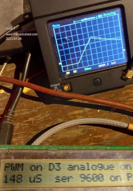
Turned back to below saturation
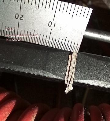
5 cards in the gap
Edited 2023-07-28 05:03 by mab1 |
| |
mab1
Senior Member
Joined: 10/02/2015
Location: United KingdomPosts: 282 |
| Posted: 07:19pm 27 Jul 2023 |
Copy link to clipboard |
Print this post |
|
So, some advice please, on the subject of building inductors:-
I'd like to make this ferrite work in this mppt, if possible, but to stay above 100uH and increase saturation to maybe >60A, i would need more turns of wire and a bigger gap.
1. How big can i reasonably go with the gap?
2. I seem to recall advice against big solid wire due to skin effect - if you have 7 strand household wire (like the blue 25mm2 above) does that count as 7 in hand? or as they are touching and not insulated from each other, do they work as one solid wire?
I need to decide what sort of wire to use as that determines how many turns and what wire size i can use.
3. What do you use as gap spacers? Even with the clamp screws tight it gets quite noisy at 50A. Or can i use card, but with epoxy or similar to glue it in the final form?
I do have a 2nd pair of these ferrite cores, so i could just double them up, but then I'd like to save those for the 2nd mppt if possible |
| |
wiseguy

Guru
Joined: 21/06/2018
Location: AustraliaPosts: 1297 |
| Posted: 10:54pm 27 Jul 2023 |
Copy link to clipboard |
Print this post |
|
Hi Mab making good progress there, I use that schmidt walter site often.
There is another variable that I dont know if it has been played with much in the MPPT and that is the switching frequency to assist with the choke behaviour.
When I was playing with my inverter nominal Freq ~ 20kHz Poida created some test code for me that used frequencies of I think up to 50kHz. In my inverter there was very little losses at 40kHz compared to 20kHz but of course the inductor requirements are much reduced. So having a play at higher switching frequency might help.
Not sure if the code allows for simple frequency change but it probably does so the saturation point could then allow the use of the one choke with greater current before saturation and maybe less audible noise also ?
I suspect the non insulated copper 7 strand would behave more like one solid conductor with regard to skin effect.
If at first you dont succeed, I suggest you avoid sky diving....
Cheers Mike |
| |
Solar Mike
Guru
Joined: 08/02/2015
Location: New ZealandPosts: 1228 |
| Posted: 01:07am 28 Jul 2023 |
Copy link to clipboard |
Print this post |
|
1. How big can i reasonably go with the gap?
Once you get over 1.5-2mm with ferrite cores I have found little difference as the gap gets larger. 20Khz is really too low for that type of core, would work better at approx 100 Khz or higher, see if the code allows a higher frequency near 40 Khz or more.
2. I seem to recall advice against big solid wire due to skin effect - if you have 7 strand household wire (like the blue 25mm2 above) does that count as 7 in hand? or as they are touching and not insulated from each other, do they work as one solid wire?
The multi-strand un-insulated wire acts as a single strand, you require multiple insulated strands; I use 0.56mm dia. multiple strands (each good 1 amp) for best efficiency, least heating.
3. What do you use as gap spacers? Even with the clamp screws tight it gets quite noisy at 50A. Or can i use card, but with epoxy or similar to glue it in the final form?
Cut couple pieces scrap PCB material, 1.6mm standard thickness for your spacer, this wont compress as you clamp halves together.
Mike
Edited 2023-07-28 11:10 by Solar Mike |
| |
| |
Page 1 of 3 |
