
|
|
Forum Index : Electronics : Expanded scale volt meter.
| Author | Message | ||||
| Gizmo Admin Group Joined: 05/06/2004 Location: AustraliaPosts: 5185 |
Hi fella's I've been cleaning up my junk pile and sorting everything into draws of components. I have a few meters from old stereo's and tuners. 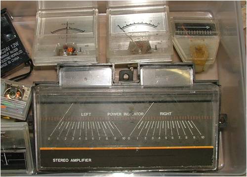
So its time to put together a project I've been meaning to do for years, a expanded scale volt meter for my battery bank. And I'll write it up as a page for the web site, as I think its a project that might interest others. This will be both a volt meter and amp meter side by side, the volt meter will be 10 to 15 volts, and the amp meter will be center zero, so will measure draw and charge. Anyway, I've researched a few expanded volt meter circuits. This one uses a handful of components, a couple of IC's, and seams a bit overboard, though I'm sure its accurate. http://www.solorb.com/elect/solarcirc/xsvmeter/index.html This one uses two regulator IC's, with the meter measuring the difference. I have a feeling it wont work, there's very little current drawn through the reg's, so I dont think they will regulate properly. http://www.edn.com/archives/1994/012094/02di2.htm And this one is so simple its ridiculous. But I like it! http://resources.metapress.com/pdf-preview.axd?code=a025q450 16228563&size=largest Has anyone come across a simple expanded scale volt meter circuit that's worth considering? Glenn The best time to plant a tree was twenty years ago, the second best time is right now. JAQ |
||||
| davef Guru Joined: 14/05/2006 Location: New ZealandPosts: 499 |
Glenn, I use a 10Volt zener diode in series with a 500uA meter and a suitable current limiting resistor. I think you want a fairly sensitive meter, but you could try a 1mA or maybe even a 5mA full scale item. Adjust the resistor for a full-scale reading at 15Volts. Actually, for good temperature performance a 5V6 and a 4V7 in series might be better, depends on the current through the diodes. The datasheet will tell you were zero temp coefficient is for x amount of current. Mine tracked within 100-200mV of the real voltage across most of the scale. Good luck. Dave |
||||
| Dinges Senior Member Joined: 04/01/2008 Location: AlbaniaPosts: 510 |
Glenn, you may want to check out this project by Commanda: http://www.fieldlines.com/story/2004/9/14/23945/6905 schematic: http://www.otherpower.com/images/scimages/2006/09590050.pdf Peter. |
||||
| Janne Senior Member Joined: 20/06/2008 Location: FinlandPosts: 121 |
This came at a good time, I was just thinking of making something similar. The Amanda's version looks too simple to skip... The CB will make a nice practice run on the cnc router :) If at first you don't succeed, try again. My projects |
||||
| woodchips Newbie Joined: 05/01/2009 Location: United KingdomPosts: 27 |
As Dave says, you just need a 10V zener diode and a series resistor. If your meter is 1mA, so 1000 ohms per volt, then you need a 5k ohm resistor. That is all. The 5.6V zener does have minimum temperature coefficient, but are you really going to notice? If you do go this route then you can trim the zener voltage by wiring forward biassed series diodes, silicon to add 0.7V or germanium to add 0.3V, in with the zener. Only slight gotcha is to not have the meter too sensitive. You want it to take the zener quickly over its conduction knee when the voltage goes over 10V, not start to dribble current into the meter around the 10V. In reality make the meter at least 1mA, or even 10mA, or put a parallel resistor around the meter. For the ammeter just wire it around any suitable length of cable. You will find that trying to make a physical shunt quite difficult due to the minimal voltage drop needed. If you do make a shunt, use a short strip of thin steel, and trim it by sawing a slot across the width of the strip. Sawing the slot will reduce the cross sectional area and hence raise the resistance. Bob |
||||
| Gizmo Admin Group Joined: 05/06/2004 Location: AustraliaPosts: 5185 |
Hi guys. I've put up the page.... http://www.thebackshed.com/Windmill/articles/ExpandedScaleVo ltMeter.asp I kept it simple for now, but will go into more detail at a later date with some of your suggestions. Thanks for the feedback Glenn The best time to plant a tree was twenty years ago, the second best time is right now. JAQ |
||||
| davef Guru Joined: 14/05/2006 Location: New ZealandPosts: 499 |
You can adjust the current through a 5V6 zener to achieve a very low temperature drift. Thanks for putting it all on one page! Dave |
||||
| sPuDd Senior Member Joined: 10/07/2007 Location: AustraliaPosts: 251 |
A TL431 can be found in every ATX power supply and most other 240V power supples. They are temp compensated and voltage adjustable if you want accuracy. Gotta say - VERY Retro Gizmo 
sPuDd.. It should work ...in theory |
||||
| The Back Shed's forum code is written, and hosted, in Australia. | © JAQ Software 2026 |
