
|
|
Forum Index : Electronics : Making Printer Circuit Boards
| Page 1 of 3 |
|||||
| Author | Message | ||||
Downwind Guru Joined: 09/09/2009 Location: AustraliaPosts: 2333 |
Making Photo resist PCB�S If you don�t have 5 minutes to spare then best you Click off now! As this may take a while to get through, and Gizmo if you think it is too much than �bin it.� There is many methods of how to go about fabricating a printed circuit board. In many ways it�s a black art of linking little electronic bits together that actually preforms a task, and it works!! (well! we hope) I have used many different methods over the years, from hand drawing direct onto the copper (not pretty) , strips of finely cut masking tape stuck to the copper, (Hmmm) Direct iron down laser printer toner ink. (not so bad??) (photocopies also work, same ink) All worked, but the effort required and the inability to repeat a board, or to make a circuit change convinced me to move forward with my methods. When I started to use the pre-coated positive resist board many years ago, I would lay up the circuit on clear overhead projection sheet using Transfer, dots and ic footprints etc. then join the pads with different size pin stripes for the tracks. It gave good results but time taking. 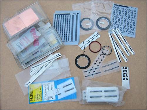
Then computers, printers and the internet with free software downloads come along. This had ability to do all the artwork and print out a copy. Even a computer illiterate person like me could do this? Great! But what I inspired to archive was to reproduce what I seen on the computer screen onto the PCB with repeatable consistent results. This has taken me to the method I have adapted to work for myself and hopefully others find it helpful to their PCB fabrication. Positive resist pre-coated board is what�s used, and it gives good results for a not over expensive cost and is not difficult to work with. One supplier is HERE I have never dealt with them, but the prices are about right and the product is a consistent quality. (Kinsten) There is a lot of boards in a sheet 300x450mm and works out cheap per board. I have only used this brand once or twice and it worked well. This sheet of double sided board is opened but not used. ( too hard ds.board) The sheets of board in the background is what I use. 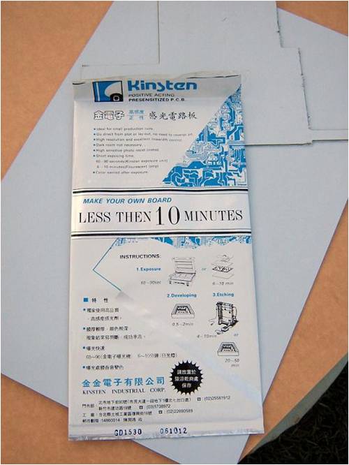
The process uses Uv light to expose the positive resist film on the board. The areas that receive exposure to Uv light will develop away and the area without Uv light exposure will remain to protect the copper during etching. The developing solution is 5 grams of caustic soda in 1 litre of water, or about a teaspoon full in 1 litre of water. Don�t try to mix any less amount, as the ratio is to hard to measure, and you may well completely strip the board if mixed to strongly. I recommend you do a test strip when you mix a new batch of developer to check the strength. (see test strip at the bottom) Basic procedure. Design artwork on a computer and print it out. Place the board on a flat surface that is rigid enough to be able to be moved ( I used a clip board for years) Align the artwork to pcb and place a glass sheet on top Expose to Uv light for the determined time period (depending on Uv light source used.) Develop board in the caustic solution till no green residue remains between the tracks, pads, etc. (over developing will give a poor result with etching) Rinse off the caustic residue in water Etch the board as per normal. Easy Ha! Sunlight exposure will also work and some fluros to at close proximity will work to some degree (if you can wait an half hour or more) I used an old bug zapper uv fluro I had found in council road kill rubbish for a long time (15-20 min exposure) 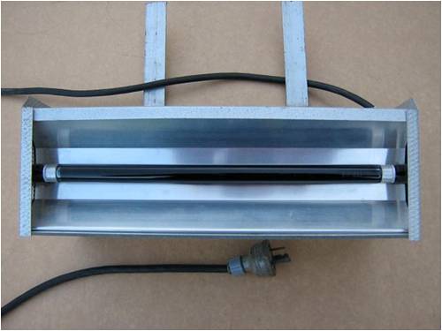
Since trying UV leds have not used the zapper fluro again. Now the step by step. Prepare your circuit artwork on the computer and print it off onto plain white paper in a high quality setting for the printer. Print in black ink. The image needs to be printed in a mirror image to what the copper view will end up to be. (back to front) Most pcb design artwork packages will print the bottom side of a board (as used for single sided boards) in a mirror image as standard. The reason for this is we need to place the ink side down onto the pcb for exposure. With the black ink in contact with the uv sensitive film no light can reach that part of the uv coating and will not be exposed. Cut the image from the paper sheet and sparingly apply a light coat of cooking oil (vegetable oil) over the Back side of the printed paper with a tissue. Rub it gently to get the oil to work into the paper. You will see the printed image appear quite clearly through the paper. Clean off any excess oil with a clean tissue. ( It pays to discard the paper after use and print a new one if several days has pass after oiling it) 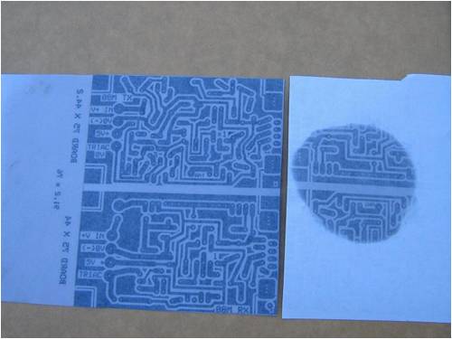
Cut the board to size ( a hacksaw works) and clean up the edges so no copper burs remain. Remove the plastic film covering the board. This will expose the green uv sensitive film on the board. Try to do this under low light levels and preferably with a incandescent light as this has no real UV light spectrum. (fluros do) 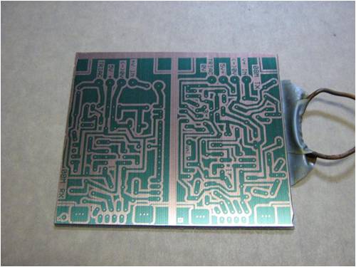
Align the printed artwork over the board ink side down Place a sheet of glass over the top of the paper to hold it firmly in contact with the pcb. Check that all is still aligned correctly, Start the uv light exposure. I find 10 passes (5 ups and backs) of the uv leds travelling at 300mm/min (slow) at a height of 100mm from the circuit board gives a good print. If the leds are used stationary than exposure time is 10 times less, as the leds only cover a strip as they travel up and back along the board. My uv light scanner was made from the carriage section gutted from an old inkjet printer and Uv led clusters. ( 2 rows of single leds work just as well) 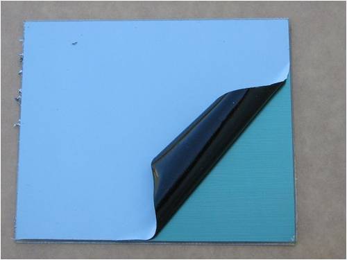
It is important to have the leds start off the board and travel the length of the board and off the other end before they reverse and return, otherwise the ends where it stops and reverses will get double exposure and wont develop uniform. 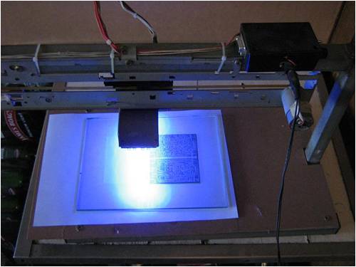
Once the exposure is started, wait till its completed 10 passes and has switched itself off. Remove the pcb and attach a piece of electrical tape to the backside of pcb with one end wrapped back around some plastic coated wire for a handle to hold/hang it from. (Not such a good method for double sided boards. Works well on single sided.) 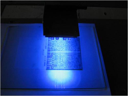
Place the pcb in the caustic solution and gently keep it moving in the solution. The image will start to appear this may be quick or slow depending on the strength and the temperature of the caustic solution. You will need to ensure all the green coating between the tracks has developed away as a light hard to see film remaining will make for a poor etch. I find that a fine line along the edge on the artwork can give a good indication when over developing is happening, as this line will tend to be noticed to disappear first. Rinse the board and inspect a few times during developing and you will soon see when it has developed fully. After developing the board should look something like this. 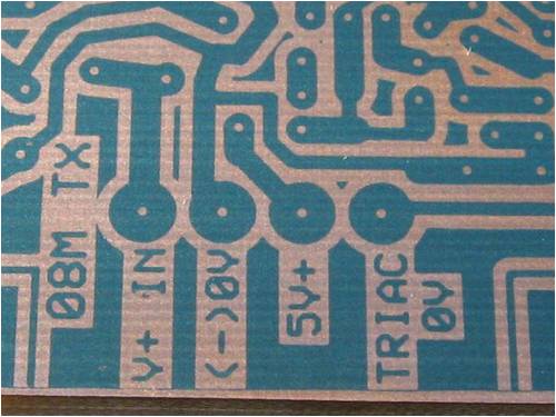
Check the board for any defects and correct them. If you have a bridge between tracks then put a scratch in the green coating, as it will then etch there. If you need to repair a track, I find a CD marker pen works well. Next etch the board and afterwards it should look like this 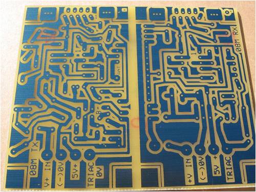
It is easy to see the quality of detail that can be achieved 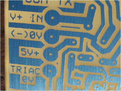
Once the board is etched the green protective film can be removed with methylated spirits on some paper towel. The board cleaned off. 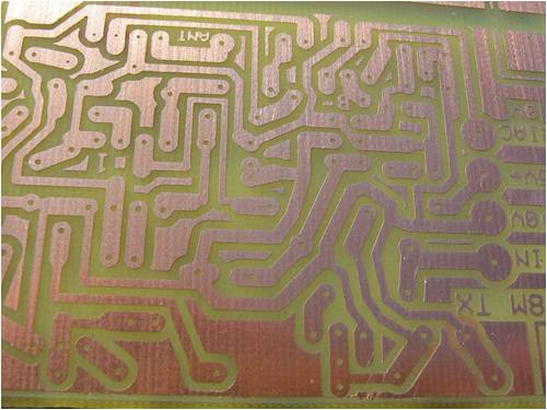
The board is tinned before drilling (or it plugs some of the holes up) I tin my boards with a solder paste and use a electric heat gun. After heating to melt the solder paste, the excess paste washes off in water leaving a thin solder layer behind over the copper areas. 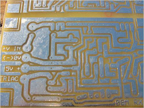
Drilling holes. The part we all love to hate. The better you set up for this the easier it gets. Old method used. I had a dremel tool mounted in an old hand drill press I had found in council rubbish that served me well for many years. A fish aquarium air pump was used to blow the dust away from each hole during drilling 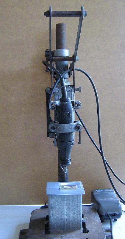
The addition of a ultra bright white led in a under table position shining upwards makes it much easier to see the holes in the pads for drilling. One was mounted in a piece of steel tube with a acrylic clear top attached. Powered from a plug pac off a discarded nokia phone. (note the anti-glare tape. Bright little blighters) 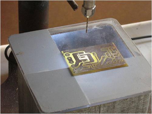
New method. As I loathed the though of drilling another board and with eyesight deteriorating with age alone, and a desire not to have to drill little bloody holes, I built a small desk top cnc router out of junk to do the job for me. Best thing I ever did!!!! 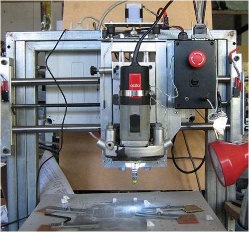
Tungsten carbide 0.85mm drill bits. Well worth the cost for how well they drill. They drill so clean and leave no burs around the holes. Good life to if you don�t break them. 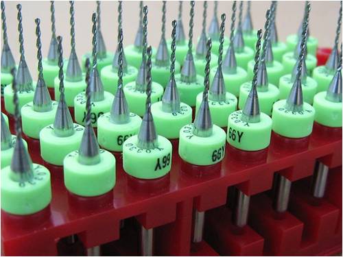
Drilling in process. 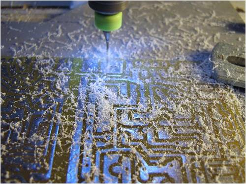
Once drilling is complete I route the board out to the shape required. 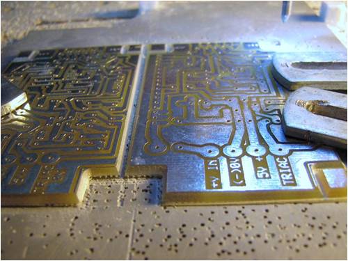
A rather well used, blunt looking pcb router bit 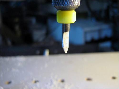
Check if all fits within the intended box. It did. 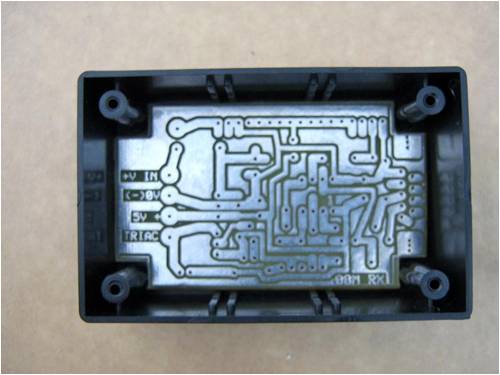
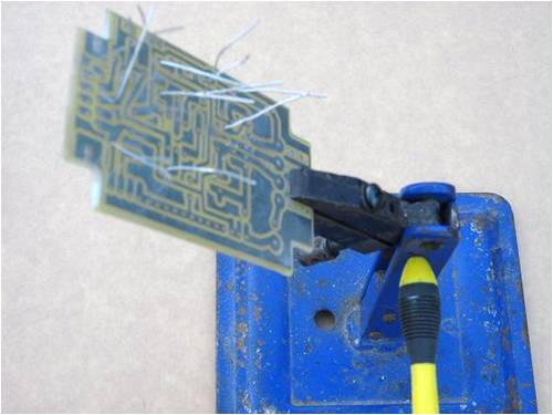
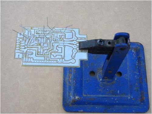
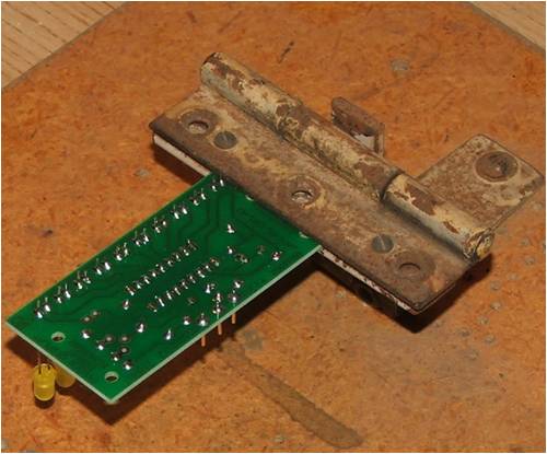
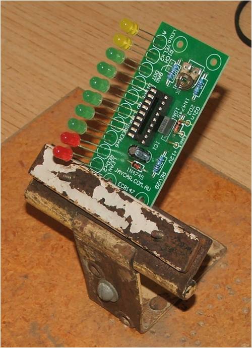
Board assembly As you will all know, one of the awkward things about assembling a board is holding the little bugger while inserting components and soldering. The little helping hands gator clips thingies are more than useless in my experience. There had to be a better way! I fabricated a pivoting clamp that can flip over one way to insert the components and flip back the other way to solder thing in place. It was another project that was well worth the effort and has given many years of service. Have since made several for others and now include a edge around the base to form a tray, as when you unsolder a component for an alteration all those used little bits end up in the tray and ready to be reused again. (or at least found) 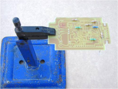
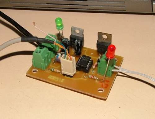
The finished boards 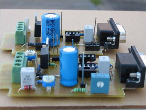
The whole process is a bit rough but it works for me and gives a workable board at the end for minimal effort and cost. The process allows me to produce a reasonable board in less than an hour from printer to assembly and if doing several boards together than this time is reduced greatly per board. You never stop learning with making pcb�s and I hope this helps others to produce fair quality boards of their own. I also hope this inspires others to post their methods of making pcb�s regardless of how simple or complicated the method is. We often use ideas from many sources to find a way that suits our needs best as I have done. What is your method? A few more tips. I think Epson has a much better inkjet, ink than canon and others for printing the artwork as it is an alcohol base ink and not water based. It prints sharper edges and is a blacker ink. I use a laser printer now but ink jet was all I had for years. There is no need to wash the board to remove any oil film, as there shouldn�t be any if used correctly. Besides caustic is a great degreaser anyhow. Design software This is a personal choice to most with what they have or know how to use. My preferred choice is ExpressPCB And can be downloaded free from here. ExpressPCB I find its a basic, easy to use software package that can be learnt quickly. Ammonium per-sulphate I use ferric chloride but many etchants will work. If you use ammonium per-sulphate it is a nice clear liquid to work with, but it don�t last as long as ferric chloride. I found mixing ammonium per-sulphate in chlorinated tap water killed it stone dead as an etchant, so use rain water or buy some distilled water. Home made etchant If you don�t have any ferric chloride or any other etchant than a etchant can be made from Hydrogen peroxide ( 3% by volume from the chemist shop or supermarket) and hydrochloric acid (HCL). From bunnings or a hardware store, even a swimming pool place. ( used as a ph adjuster ) Mixed at a ratio of 2 parts hydrogen peroxide to one part neat hydrochloric acid. The solution will turn a redish colour by memory when mixed. ( or was it green??) The life of the solution will only be a few days as it will oxidize quickly and become slow and take all day to etch. Fresh it will work fast and gives a good result. (10 �15 mins ) Copper recovery If you want to recover the copper from a well used lot of ferric chloride before It is discarded, than place a strip of black or uncoated steel sheet metal in the ferric chloride over night. The next day the copper will be crystal like on the bottom and the dark brown ferric chloride will be almost clear hydrochloric acid again. It will not be any good as a etchant after this. Pour the acid off and recover the copper . It is hard to believe, that this dark thick gunk can change so much with the introduction of a bit of steel. Test strip. Keep all the small little offcuts of the pcb sheet to be used as exposure test strips. A test strip is done by exposing an artwork image onto the pcb in stages of time. An example is. Place the artwork on the strip of pcb and expose it for a minute, than place a piece of cardboard over a small portion of the strip one end (10-20mm), expose it again for another minute, then move the cardboard along a little more and expose again for another minute and so on till you run out of pcb strip. Then develop the strip as normal and you will see at what time period of exposure gave the best results. If the test shows over or under exposure through out, than repeat the test and adjust the time period to suit. It is a test well worth doing and is much cheaper than stuffing up a complete board. Once the exposure time is established than it should remain the same, if the same conditions as always used. ( hence why I use a uv scanner method) It dose pay to do a simular test when mixing a fresh batch of caustic solution as I have stripped a board clean in developing with the solution being to strong ( I think I said whoops , bugger and then *%$#@!!) Short cuts never pay!! A good investment is a head set magnifier and once you have one, you will ask yourself how did you made do without it. 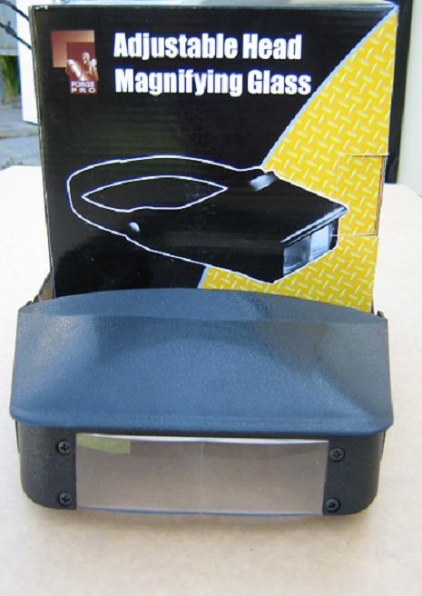
The local $2.00 shop �Cheap as Chips� had these out recently for $5.00 . They have a second flip down lense for double magnification ( maybe needed in future years) Well worth the money. ( I bought a $30.00 set a few weeks before these came out and now prefer using the cheap ones.) I can now read those tiny printed part numbers. I am told they work well if you wear glasses, as there is no need to remove your glasses. Funny how fast the soldering becomes when you can see what you are doing. Best get two sets or the misses will steal them for needle threading or whatever?? or the kids may nic them to burn bugs with. (if kids still do that) Pete. Sometimes it just works |
||||
| Tinker Guru Joined: 07/11/2007 Location: AustraliaPosts: 1904 |
Hi Pete, Your first picture showing the black Bishop tapes and pads brought back memories, I used to lay out PCB artworks for a living back in the seventies. Great fun, double sided boards laid out on a gridded light box with targets for alignment. One track between IC pins was as complex as it got back then and plated thru holes became only standard in my last years working in that field. Never did any etching though, my artworks were sent to a shop that photographically reduced them and then manufactured the boards. Mistakes with that method were expensive and frowned upon by the boss, not many frowns for me  . .
Now its all computer design - will have to give that a go one day - and, thanks to your excellent article above, the etching bit does sound doable even for an old bloke like myself. Well written Pete  Klaus |
||||
| Dinges Senior Member Joined: 04/01/2008 Location: AlbaniaPosts: 510 |
Excellent write-up, excellent pictures. You've obviously put quite a bit of time into it. Deserves a place on the front page, in my not so humble opinion. Have made many etched PC boards in the past (using a spray to make the boards photosensitive, 'Positiv 20'). After initial problems, testing, changing procedures, etc., this method of making boards worked reasonably well for me. It's just something that I utterly, deeply and totally hated doing. And the drilling (even using a proper drill press) that followed it was enough to really spoil my day. The downside to those etched PCBs I find to be the inflexibility to modifications or using slightly different components (different mechanical size) than the designer intended. As basically everything I build is a prototype, I've grown very fond over the years of perf board (not the kind with the strips, but with small copper pads). It's very flexible to use, easy to change things, and, best of all, you can build *extremely* compact circuits using it. I also find that adding SMD resistors or capacitors works fine. Here's one of the latest projects (also very much in progress), a sinker EDM machine: http://picasaweb.google.com/motorconversion/SinkerEDM#539472 7798897988226 Point-to-point wiring takes a bit more time when doing the actual wiring/soldering, but when taking into account the amount of time it takes to make a PCB, I think you'd only be ahead timewise for very complicated projects. Or actual production runs. In my early electronics days I used nothing but etched boards, but nowadays I use nothing but perf board anymore. Though, for RF purposes, I'd still go back to etched PCBs; haven't done much RF in the past few years, so not an issue for me at the moment. The few times I did it was much easier to cut striplines with a knife (in Teflon print). I tried the photocopy method too (heat transfer the toner to the PCB), but never quite got it to work for anything but the very simplest boards. Even though I tried different printers, toners and paper. Admittedly, perf board takes a bit more time building, but using proper procedures, the boards are at least as reliable as etched PCBs. Future modifications are much easier though. And considering the time it takes etching and drilling PCBs, I doubt there's much time benefit for one-off products. Unless you have a CNC router and drilling machine. Incidentally, one of the ideas behind my CNC router (WIP) is to use it for milling PCBs and drilling the holes. I very much like the idea on how to tin PCBs - it never occurred to me to do this your way, seems like an excellent solution. (I do routinely use the heatgun for depopulating boards). And I do agree with the handiness of board clamps - I'm using a Panavise and love it very much. Only regret is not getting one 15 years sooner. Have you considered modifying an old flatbed scanner with an UV light source? Seems like an easy solution, with all the mechanical bits already present; just tap in to the board that drives the stepper motor and add your own pulses/signals to control the motor. In the past I used HNO3 (saltpetre acid) to etch boards. Worked pretty well for me. Fast and cheap acid. Noxious fumes though, must do the etching outside as the NOx really hits your lungs. Of course, one should also etch outside using FeCl, as the vapours are corrosive. NaOH (natrium hydroxide) used to be available in powder form over here. Dosage was pretty important, as a too strong solution indeed removed *all* photoresist from the board, instead of just developing the exposed bits. Also, do not use a finger for stirring the fluid. It never hurt, but the next day my finger nails would turn brown and skin started peeling off the stir-finger... +1 on the carbide drills. Just don't use them when drilling by hand, they're guaranteed to break. Very hard and durable drills when drilling glass (FR4 board), but also very brittle. Good tools make a job so much more pleasurable. Which probably explains why I spend more time building tools than using them.... 
Peter. |
||||
| GWatPE Senior Member Joined: 01/09/2006 Location: AustraliaPosts: 2127 |
I would never use Nitric acid to etch copper boards. The NO2 [brown fumes] is very toxic. Pine box toxic. Well written article Pete. Will help many others. Gordon. become more energy aware |
||||
| Gizmo Admin Group Joined: 05/06/2004 Location: AustraliaPosts: 5185 |
Yes I agree Pete, well written with great pictures. I would like to put it on the main web site as a article for everyone to read, is that OK? That way it wont get lost in the forum over time. Glenn The best time to plant a tree was twenty years ago, the second best time is right now. JAQ |
||||
Dingdoc Regular Member Joined: 23/09/2009 Location: AustraliaPosts: 76 |
Peter (Downwind)- Excellent article - well done! Your CNC drill looks great - I am sorely tempted to start building one but the F&P mill would never get finished!! I was wondering if the carbide bits would work OK in a drill press or would they be to brittle - where do you buy them from? Another way of treating the spent ferric chloride is to add carb soda (Sodium carbonate) or bicarb soda and allow it to stand - the insoluble copper carbonate settles out allowing the clear liquid above to be safely poured down the drain without the toxic copper. Also, re the Epson ink producing better results, their Dura Brite inks are pigmented with microscopic particles which improves the opacity whereas most other inks are dyes which tend to transmit light more readily. Peter(Dinges) - I got a chuckle out of your chemical names for nitric acid and sod. hydroxide - not sure if they are 'old' terms or 'Dutch'
The OHS nazis would freak about your etching with Nitric acid and mixing NaOH with your finger, although I have to admit to rejuvenating my ferric chloride many years ago by electrolysis with a couple of carbon rods from old batteries - not sure if it produced chlorine gas or HCl fumes - certainly wouldn't recommend it!! Trev |
||||
| Downwind Guru Joined: 09/09/2009 Location: AustraliaPosts: 2333 |
Hi , Thanks guys for the kind words on the artical. Its nice to hear about some of your stories to. Yes a bit of work did go into it, and i took over a hundred photos to end up using 20 something of them. It seemed pointless to do a half job, as that would help no one. A picture speaks a thousand words. I left a lot out, as it got big enough, fast enough as it was. (thought Gizmo might growl at me if it got too big) I assumed that people would know how to place the board in etchant etc. As for putting it on the main web site thats fine by me. Maybe hold off for a bit and lets see what input from others we get and if any changes or additions are asked then i will do that for the main page. I feel that i am clogging up the main site with my crap! but if you guys dont mind than i dont either. I have thought about doing a How to make the uv scanner artical as well if there is any interest. I did consider the flat bed option but would rather have the print on top as it is easier to align and to see it is all correct before exposure. Besides old printers are always out in council rubbish everywhere here. One off boards never seem to be one offs for me, so to do prototypes on perf board only means re-doing it all again in a pcb, so i find it quicker to do the proto on pcb and make changes to suit after. Doing the artwork is like doing a crossword puzzle for me.I actually enjoy it. It also allows me to email the circuit to others who wish to do the board. (bit hard emailing a perf board) A tin paste is also available but when i bought the solder paste as a test i thought tin had a higher melting point, I was wrong it is a lower melting point. The only drawback with tinning a board is you use a little more solder as it tends to wick out along the tracks a bit more, but solders much easier. Pete. Sometimes it just works |
||||
| Downwind Guru Joined: 09/09/2009 Location: AustraliaPosts: 2333 |
Dingdoc, The drill bits i buy off eBay out of china for around $20.00 for 10. If you search ebay for "Dremel bits" it should give a vast range of suppliers and lots of different sizes. If i was only to buy one size than it would be 0.9mm as i find almost every thing will fit this size hole, including header pins and v-regs etc. snuggly. If you have trouble finding them that ask again and i will track down the supplier i uses. I have used them in the dremel press ok but you need high speed or they will screw into the board like a screw and snap off. Did you notice in the photo the cuttings from the drill are like little squiggly worms and not so much the fine ground powder the normal bit produce. I still use the normal bits to oversize a hole as they are more forgiving in a cordless drill and its normally only one or two holes a board anyway. The cnc project is well worth having a go at and you will thank yourself for doing it for a long time. The things you will make that you would have never considered having a go at in the past will amaze you. When you get to doing it let me know as i can help there to with where to get some various bits and pieces from. Best P.Y.F.O and finish that mill so you can start a new project. Pete. Edit. I said search "dremel bits" you ned to search for "dremel drills" try HERE Sometimes it just works |
||||
| Gizmo Admin Group Joined: 05/06/2004 Location: AustraliaPosts: 5185 |
Hi Pete I dont think the forum software has any limits on post size, and either do I. Of course if anyone is planning to write up a long post, its always a good idea to type it up in notepad or any other word processor first, it can be depressing to type up a long post online only to have it crash on you before it was saved. I do enjoy the articles contributed by forum members, and there is always room for more. I want the site to become a library of informative projects and articles, and keep it all available for free. I'm working on a better menu system and page layout that makes the pages easier to find, read and print, its a work in progress. I'll give it a few days before I look at combining the posts into a article on etching circuit boards. Now for my own contribution. I've used my own CNC router to make a few small circuit boards, nothing fancy. Below is a test run. 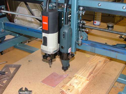
And this is my PicAxe based pump controller. Its not pretty but it worked. 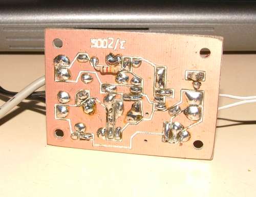
In the latest Silicon Chip magazine there is a review of the Roland EGX-350 desktop cnc router. They are using it to make circuit boards, using a software package called CopperCam http://www.galaad.net/coppercam-eng.html. It costs about 80Euro ( the software, not the router ), but I think there are similar programs out there for free. Glenn The best time to plant a tree was twenty years ago, the second best time is right now. JAQ |
||||
| Gizmo Admin Group Joined: 05/06/2004 Location: AustraliaPosts: 5185 |
Speaking of CNC, I put together a little web site about my own CNC router some time ago. If anyone is thinking of making their own, they find find it usefull. http://www.thebackshed.com/cnc/default.asp Glenn The best time to plant a tree was twenty years ago, the second best time is right now. JAQ |
||||
| Downwind Guru Joined: 09/09/2009 Location: AustraliaPosts: 2333 |
Now thats what i want to see or encourage. Other peoples efforts of "Having a go" I to think knowledge should be free. The name "The back shed" implys to me what many of us do in the back shed. This is a vast subject and i think it is great to have a platform to show these things. I might be rather new here, but would like to get more people to contribute their projects and ways of doing things as we all have a common interest TINKERING and in seeing someone elses project often inspires us to get off our backside and have a go at one for ourself. Gizmo if you would like a dos based program to decode the Expresspcb dxf file into a drill code (G-code) for use with a cnc machine to drill the pcb holes than let me know. Pete. Sometimes it just works |
||||
| Gizmo Admin Group Joined: 05/06/2004 Location: AustraliaPosts: 5185 |
Actually, I have a windows based one I wrote a couple of years ago when I was working at a laser cutting business. It takes a DXF file and creates the G-code to suit. It has a library of materials, speed and costs, and gave a pretty close cost of the job, usefull for quoting. I also used it on my cnc router. I plan to put it on my cnc site when I get the time. Below is a screen shot. It would be good to get these utilities in one place. Glenn 
The best time to plant a tree was twenty years ago, the second best time is right now. JAQ |
||||
| Downwind Guru Joined: 09/09/2009 Location: AustraliaPosts: 2333 |
You are ahead of me. The one i have is very basic but i am new to cnc and need to keep it simple as i learn and move forward. I would be interested in having a play with it if i am able. cnc software is hard to get without spending big bucks. Pete. Ps. expect a large email an some other stuff. Sometimes it just works |
||||
| Dingdoc Regular Member Joined: 23/09/2009 Location: AustraliaPosts: 76 |
Here are some pics of quick and easy board holders. They are certainly not in the same class as Downwind's engineered masterpiece but still beat chasing a small board around the workbench. The first is just a block of wood with one or more cheap mini spring clamps from the two dollar shop screwed to it - 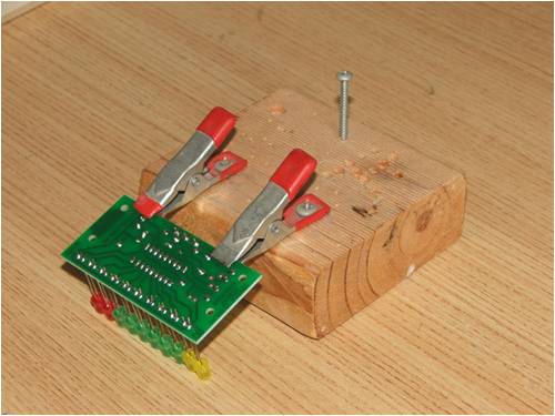
This one was made from an old hinge about 30 years ago - 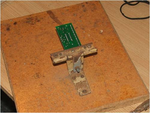
Thanks for the info too Pete - would like to see more details of your cnc machine. Trev |
||||
| Downwind Guru Joined: 09/09/2009 Location: AustraliaPosts: 2333 |
Good ideas Trev. They are simple but practical which is what many are looking for. As for mine being a masterpiece? not sure if i would put it that way. It works. The cnc router is the second one i have built or i should say the first one mach2 as i had rebuilt the Y axis and Z axis on this one, hence the multi layer tubing frame. I had the intension to rebuild the X axis (table) as well but not yet got to this, so Y & Z were adapted to the old frame on the X axis. As the previous Y, Z was kicking about on the floor i built another X axis and reworked the bits off the previous Y,Z to make a complete cnc router for a good friend of mine, so he too can drill boards with ease. There is a mass amount of work in making one and you wont get much change out of $500.00 by the time you buy the few bits and pieces you need. I looked at buying a bought one and prices started at around $5000.00 and jumpped to $50,000.00 real quick. I could not justafie the cost for my needs so thought i would have a go at making one. It felt like a never ending project but i got there. The first run around with a broken drill bit and a paper print out of a circuit, that i could press indents into the paper and not punch through it in all the pads gave me a smile bigger than the grand canyon. I looked at building the motor driver board, but by the time i added up all the driver chips and other components it was about the same price as a complete 4 axis board out of China for $100.00 so i took that option. I use Mach3 as the cnc software and only have the free demo version. This will only allow me to go to 500 lines of code which is very limiting to the work you can do, as a circle cut could be 2000 lines on its own. There is always a way to cheat this but a pain in the butt just the same. I will try to find some time on the weekend to take some photos and put a short discription together. It is far from a work of art as i made use of what scrap (better said without the S )i could find to do the job. I do intend to build another one with all the good bits in it, so i can machine down to 0.01mm as at present i can get around 0.1mm accuracy or better. Trev i can hear your cogs of thought clunking away in the background.
Pete. Sometimes it just works |
||||
| Dingdoc Regular Member Joined: 23/09/2009 Location: AustraliaPosts: 76 |
Oh! If only I had the time!! I think I am going to need several lifetimes to get everything done that I want to!!! Still, its better than being bored. A while ago I bought a s/h Oce A1 size pen plotter with the intention of using the bits to build something like this, but it is such a fascinating machine to watch working that I haven't had the heart to reverse engineer it. It came in handy to draw out a copy of Gizmo's CAD plans full size when I was starting on my mill and I was able to modify them before sending them to the laser cutter. I think I will start collecting bits for the CNC but today I looked at a 'proper' Dremmel to fit to a drill press as a stop-gap. Up till now I've used a 'toy' pcb drill which has been a pain to use because of the slop in the chuck bearing which made it hard to locate the drill tip on the pad. BTW, Pete, I think that the more 'Heath Robinson' a machine looks the better - they look like they've been built by a real person and not made in a factory by a robot. My modded Epson C63 looks much better now all of the covers have been ripped off and you can watch all of the innards working when it prints a board!! I look forward to seeing your photos - I've already admired Gizmo's, one of the first things I looked at when I found this website. Trev |
||||
| Downwind Guru Joined: 09/09/2009 Location: AustraliaPosts: 2333 |
Trev, Do the toy pcb drill have a collet insert for the bit to fit into. A friend had one and found the collet fitted nicely into the low priced Super cheap auto's rotary tool (dremel rip off) as these take a slightly bigger collet than the dremel brand. Dremel is good and i have had 2 in 30 years but would buy the cheaper made ones now if the collet can be got to fit the drills. The carbide drills are not a problem its the normal drills i mean. $40.00 for the cheap'os and $140.00 for dremel El-cheapos life might be shorter but not by 4 times less. and they come with a flex shaft. Pete. Sometimes it just works |
||||
| Dingdoc Regular Member Joined: 23/09/2009 Location: AustraliaPosts: 76 |
There are 5 different size collets in the toy drill Pete. I did not consider the cheaper rotary tool at Mitre 10 because I assumed it would also have too much slop in the bearing and I would be no better off. The Dremmel I looked at did not come with the flexible shaft and was $99 with a selection of accessories. Up till now I've always considered them a bit 'Mickey Mouse' and overpriced - after all, why would anyone muck around trying to remove metal with one of their dinky little grinders when you could lay into it with a decent angle grinder and get the job done quickly!! I'm not sure if the flex would be of much use - what are your thoughts? Trev |
||||
| Downwind Guru Joined: 09/09/2009 Location: AustraliaPosts: 2333 |
Trev, I only bought a flex shaft for my dremel a few months back as found one real cheap and never thought i had a use for one before. I do find it handy for the odd thing like cutting out the box to mount a plug through and things like that but optional. The other cnc router i made runs a super cheap autos brand tool on it (was on special for $20.00 at the time) and has little run out when routing and i think it is better than my dremel in that area, but mine is many years old and done a mass amount of work. I did replaced the bearings in mine resently even though you are not ment to be able to, and buy a new shaft instead, but tool is to old to get a new shaft. I still had run out so shimmed the bearings in the plastic housing and it made a world of difference. Mine has a 2 piece shaft and a bad design as it allows movement between the two. This has been changed in the later models to a 1 piece internal shaft. I would take the collets from the toy drill with me and the tool they fit into is the one i would buy. It is very difficult to get the collets with a small hole for the drill bits and you already have them. I find the little chucks that come with the dremels useless as they dont centre worth crap on fine drills an wobble to much. If you run one of these tools on a cnc router it gets a lot of sideways thrust applied to the bearings and they are not designed to take that sort of load being a hand tool, thats why i bought the el-cheapo ozito router rather than stuff up a $100.00 handy tool. I cut down a flex shaft from a el-cheapo rotary tool to make the adaptor for in the ozito to take the 3mm shaft cutters and drills i use. I think you will find a range in the dremels and the $99.00 ones is in the lower watts range and the lesser quality one as when i looked last i needed to spend $150.00 or more to get something a bit more robust in the range. Dont get lead by all the free cutters and grinding stones some kits have, it might look like a good deal but really they are useless crap you will more than likely never use much if at all. A few good cutters that cost a bit is worth having and you will do more with them than all that other junk put together. So conclusion buy what your heart tells you more so than me. If it was me i would buy a tool the collets fitted and was cheap with minimal slop in the shaft and bearings, then spend those dollars saved on a few good cutters of different styles. When the tool dies in time buy another cheap one and you may still have the good cutters from the beguining. The only reason i have a dremel is it was about the only one on the market back then. Now the range is large and a fraction of the price i paid. Hope this helps. Pete. Ps. they are a great tool for electronic tinkering and small hobby activities with a zillion uses but no i would not use it in the welding shop or carve a canoe with one. Sometimes it just works |
||||
| Dingdoc Regular Member Joined: 23/09/2009 Location: AustraliaPosts: 76 |
Pete Just a quick message to let you know I settled on the Dremel - picked it up this arvo. Tried my collets in the cheapie they had and they didn't fit but thanks for the suggestion. The cheapie seemed to have a little play in the bearing and was around $50 so I figured it was better to pay the extra. My brother has just bought a lathe so I may be able to convince him to make me some collets to fit if I find I need them. Also dug out a drill press designed to take an electric drill which I had collecting dust in the shed (don't think I ever used it) and it will take the Dremel without too much modification. Surprisingly, it looks almost identical to the Dremel one which sells for around $90!! Just goes to show that if you keep that junk long enough it will eventually come in handy (or so I keep telling my wife when she suggests a cleanout). Now I just have to order some carbide bits and I can do something a little boring. Thanks for your advice, Trev |
||||
| Page 1 of 3 |
|||||
| The Back Shed's forum code is written, and hosted, in Australia. | © JAQ Software 2026 |
