| |
Page 1 of 3   |
| Author |
Message |
KarlJ

Guru

Joined: 19/05/2008
Location: AustraliaPosts: 1178 |
| Posted: 10:38am 25 Jan 2010 |
 Copy link to clipboard Copy link to clipboard |
 Print this post |
|
Long story short have some Q's for circuit protection
PVE1200 (GTI) has its own DC breaker so wire batt direct
with no additional circuit breaker
yes/no
Mill end has stop switches -do I need batt isolator also
yes/no (and if so How big -Figure it might see 20A if i'm lucky 20x60= 1200W so 32A (1920W)?)
Batt end to mill
do I need another breaker to mill
yes/no (if so assume same size as mill end)
Batt to PL20
I have a 20A automotove blade fuse to the PWM dump load
(load terminal)
dump 1 is rated at ~870W at 59V 900W at 60V thus 15A max draw.
and 20A breaker in Neg line (from PL20) to batt
PL20 G terminal to relay for dump 2 -nothing.
Jezus 2nd dump (if 1st dump fails or overvoltage occurrs)
this dump rated at 400-1600W @60V
(I will go for 1200W for now)
Connected via relay to batt direct
should I add another 32A breaker?
So I'm thinking I need 3x32A breakers more than I have now.
oh an BTW currently everything is in 16mm2 cable
(about 5Gauge)
Here's a pic of what I think it will end up as
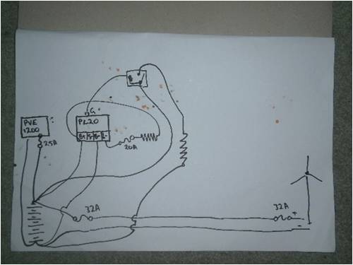
Couple of Other things I would note, under no circumstances should it be possible to have the turbine connected to the inverter without the batteries as I think it may fry something, I think I have this covered in the sketch.
In addition there will be a shunt in the Turbine input for Amp measurement (Volts taken care of via the PL20)Edited by KarlJ 2010-01-26
Luck favours the well prepared |
| |
Hank Onthewater
Newbie

Joined: 24/01/2010
Location: AustraliaPosts: 2 |
| Posted: 01:00am 26 Jan 2010 |
Copy link to clipboard |
Print this post |
|
Hi KarlJ
First a disclaimer: My experience with wind generators is limited to one Air-X, but intending to get more in depth knowledge; hence for me joining this forum.
I have installed some (marine) solarystems, and have some understanding of elec-tricks [sic].
Q1. PVE1200 (GTI) has its own DC breaker so wire batt direct
with no additional circuit breaker
yes/no
Why would you add another in-line circuit breaker if your inverter (PVE 1200) has already one? It only introduces more complexity and voltage drop.
Q2. Mill end has stop switches -do I need batt isolator also
yes/no (and if so How big -Figure it might see 20A if i'm lucky 20x60= 1200W so 32A (1920W)?)
Your drawing shows two 32 Amp fuses in the same line: one at the battery end and one (existing?) at the wind mill end. Your text enquires whether to add an switch (isolator) to the battery end. I can't see the use of 2 fuses in one line. Keep it simple. Although, a switch could be added for convenience if the wind mill end is faaaar away and a looong walk.
In fact I would keep all switches and fuses together at a central point i.e. at the batteries/inverter. Trouble shooting becomes that much easier. Then one switch/circuit breaker would suffice.
Your power calculation has me miffed. I thought that fuses trip on Amps not on Voltage. Yes, fuses may have a voltage rating, but other than that, Watts are irrelevant.
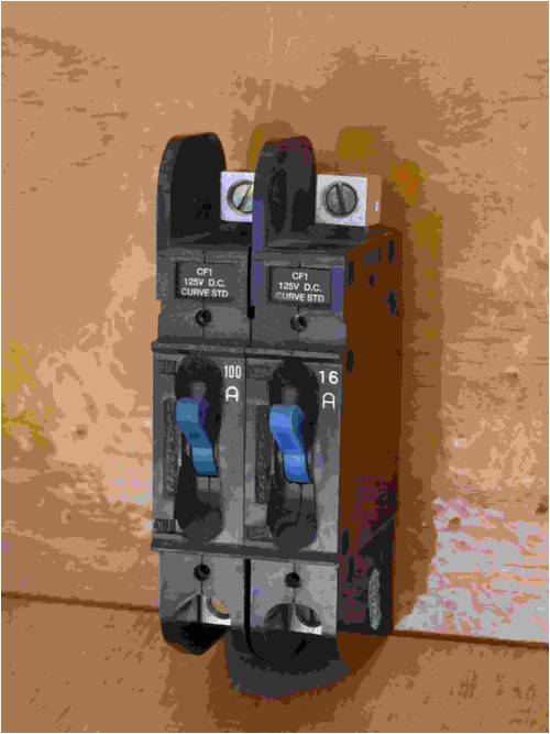
BTW, I have used on many occasions a Heinemann unit (circuitbreaker/switch) as pictured, made for DC (rated up to 125 Volt).
Q3. Batt to PL20
I have a 20A automotove blade fuse to the PWM dump load
(load terminal)
dump 1 is rated at ~870W at 59V 900W at 60V thus 15A max draw.
Again I am confused with Amps/Watts and fuses. I will leave my confusion for what it is: maybe lack of experience, until somebody can enlighten me.
I have installed a few PL20, but never with a wind generator. A 20 Amp fuse in this 'load' line may be beneficial. However if the PL20 is fused in the mill supply line and in one of the battery supply lines (or better: both) and a dump load can not draw more than 20 amps, than a fuse in the load line is not really needed.
Remembering the 32 Amp fuses in your drawing: something does not match here and if the mill is supplying more than 20 Amps you need to consider 2 options:
1. to make a change to the PL60 (good for 30 Amps on the 'load circuit')
2. to use a relay to switch the dumpload.
Otherwise, all these fuses should be of the same value: 20 amps for the PL20.
Q4. PL20 G terminal to relay for dump 2 -nothing.
Jezus 2nd dump (if 1st dump fails or overvoltage occurrs)
this dump rated at 400-1600W @60V
(I will go for 1200W for now)
Connected via relay to batt direct
should I add another 32A breaker?
I can't recall a 'G' input on the PL20. Maybe I worked with older models. Or you are using one of the programmable outputs (voltage activated?).
A relay could be used on the 'load circuit'. In fact I adopt this as my standard-first choice as this option would separate windmill output from the controller: not showing the full amps and voltage on the 'load circuit' of the PL20.
I would not have a second dump circuit. But I am open to suggestions why one would need a second dump circuit.
Fusing: only a small fuse would be needed (to supply the coil current), while the dump circuit would need a fuse to the max output rating of the windmill.
When you are using a relay, add a diode across the coil to prevent spiking/back EmF.
As far as the activation of the dumping of excess load there would be settings to adjust and tinker with on the PL20. I have no experience with that.
Another thought: if you are using two dump circuits both controlled by the same controller, how you do make sure that only one works at one time? If both dump circuits would be activated simultaneously, they would dump more power than the wind mill would generate and therefore flatten the batteries.
If the PL20 were to pack it in, then neither dump circuit is likely to work. I guess in any case the controller is the weak link, not the dump resistor or its wiring. Anyway, maybe another reason to use only one dump circuit.
Sorry for the long response.
~ happy onthewater ~ |
| |
Downwind

Guru
Joined: 09/09/2009
Location: AustraliaPosts: 2333 |
| Posted: 04:15am 26 Jan 2010 |
Copy link to clipboard |
Print this post |
|
FUSES ??
If the fuse Karl has shown at the mill end blows then there is no load protection to the mill what so ever.
The same goes for a line input fuse at the battery end.
If either fuse blew than the mill would be unloaded and you have a runaway mill.
So do you put a fuse on the line input from the mill to the battery??.
If a fuse is placed in the input line, one thought might be to place a relay across the fuse to activate a mill dump should the fuse blow.
This theory is untested and and not completely thought out.
Others points of view on it would be interesting.
Pete.
Sometimes it just works |
| |
KarlJ
Guru
Joined: 19/05/2008
Location: AustraliaPosts: 1178 |
| Posted: 04:15am 26 Jan 2010 |
Copy link to clipboard |
Print this post |
|
some rational
G terminal is programmable so if i set it for an alarm voltage (60v+) it will trigger the big dump load.
the two dump load option was suggested by some really bright guys here on the forum for a couple of reasons.
dump load resistance increases as the dump gets hot, thus inrush Watts and continuous watts are quite different.
if i size it for the full 20A rating at 59V then continuous duty may be only 15A -not enough for 1% of the time.
but the 2nd dump is there for emergencies should I get a cold day and grid goes down I dont want to pop the fuse for the dumpload and the be left with nothing and similarly I dont want to pop the PL20 by not having it fused or by using a bigger fuse.
Murphys law states that if i dont cover all the bases twice something will catch fire or wreck expensive bits like batts and inverters.
reason i thought 32A breakers at either end is it protects the wiring in case of line fault as opposed to mill malfunction. also could be handy if i want to work on mill end as mill must be shorted prior to disconnecting batts as otherwise the caps can accumulate lethal voltages
i like long responses give me more to think about.
Luck favours the well prepared |
| |
KarlJ
Guru
Joined: 19/05/2008
Location: AustraliaPosts: 1178 |
| Posted: 04:50am 26 Jan 2010 |
Copy link to clipboard |
Print this post |
|
Pete,
i like it only prob i see is the mill wont blow the fuse but a failure causing a short would.
so the circuit here needs to be at the mill end
thus the relay might have issues as the voltage may be all over the place.
so what actually happens if the mill is unloaded, will it overspeed a little then furl or will the overspeed cause it to fail to furl at all.
i think if it were set up to furl at max output, say 550-600rpm. then if it saw 700rpm unloaded then furled it should survive at that with some margin of safety (albeit small)
phills mills have both seen 750rpm and some blade damage evident (but still in use unrepaired)
All of this shows me that being a reliability engineer would / could end up quite complex and the complexity always reduces reliability making it tougher again!
Luck favours the well prepared |
| |
Downwind
Guru
Joined: 09/09/2009
Location: AustraliaPosts: 2333 |
| Posted: 08:21am 26 Jan 2010 |
Copy link to clipboard |
Print this post |
|
As i said not thought out completely.
I often see a problem in some circuit ideas posted, albeit up in the 1-5% possiable failure range, The worst end of the range normally, i think.
Do we say nothing, or do we point it out?
If we point it out , then whats the solution??
I dont know how a mill will react in a unloaded runaway situation.
I would think fully furled with no load and good wind, it would still reach high speed.
But i dont know and would not want to find out the hard way.
The relay idea was just a thought i threw out there to be torn apart by the wolves.
As for the voltage to the relay this would be likely not to be too high as the dump load would be sinking almost everything the mill generated.
The dump could be a simple short across the DC lines or across the AC phases.
If the mill power fell below the hold in current of the relay it would open, and as the voltage rose the relay would latch closed again dumping the load.
As you say where do you stop with complexity and say enough is enough.
Pete.
Sometimes it just works |
| |
oztules

Guru
Joined: 26/07/2007
Location: AustraliaPosts: 1686 |
| Posted: 10:38am 26 Jan 2010 |
Copy link to clipboard |
Print this post |
|
My opinion:
1. The only thing I want between the batteries and the mill is the diode block and a fusable link (100A ?) on the batt terminals to mill.
2. The Dump load should be diode isolated from the batteries. This will prevent the batteries being flattened by the dump load in case of malfunction. It can only draw power from the mill, but referenced from the battery.
3. The grid inverter should be directly connected to the batt bank.. with or without extra fusing... what ever makes you feel better. This will have nothing to do with the mill anyway.
4. Keep it simple. The relay system described by Downwind is nice, and can be a catch all..... but if you blow the fusable link it is because of shorted mill, or shorted diodes..... both will shut the mill off.
With a F&P you will not blow a fuse from overpowering anyway. The armature reactance will prevent this. So you only want to protect the batteries from explosive shorts... hence fusable link.
Other than that, you want/need a load on the mill. For a blown fusable link you have catastrophic failure, and this will be a direct short on the battery. The fusable link should release the battery from this without vaporising the thing that is shorting the batts. This will leave it across the mill... just what you want.
Separate diode rectification to the dump load will prevent battery discharge is case of faulty dumping. If their diodes fail, they will just stop the mill.... so no fuse at all... no battery problem.
With Al blades you don't want runaway. With wooden ones it will likely only be the ends which will disappear over the horizon, with Al, it will be the whole blade... so must not be allowed to happen.
.........oztulesEdited by oztules 2010-01-27
Village idiot...or... just another hack out of his depth |
| |
KarlJ
Guru
Joined: 19/05/2008
Location: AustraliaPosts: 1178 |
| Posted: 12:51pm 26 Jan 2010 |
Copy link to clipboard |
Print this post |
|
OK so a fusable link to the Batts from the mill, that way can be inadvertently turned off by an uneducated idiot, and when the educated idiot is playing with the mill and accidentally shorts it at the mill end it wont be like hiroshima in the shed!
can I diode isolate the dump load without putting it (the diode) in the mill circuit?
When you say a fusable link do I need proper fuse link wire? or can I cheat and pinch one off a car alternator circuit.
BTW are you telling me when diodes fail they fail closed!
I would have expected them to fail openEdited by KarlJ 2010-01-27
Luck favours the well prepared |
| |
oztules
Guru
Joined: 26/07/2007
Location: AustraliaPosts: 1686 |
| Posted: 10:24pm 26 Jan 2010 |
Copy link to clipboard |
Print this post |
|
[quote]OK so a fusable link to the Batts from the mill, that way can be inadvertently turned off by an uneducated idiot, and when the educated idiot is playing with the mill and accidentally shorts it at the mill end it wont be like hiroshima in the shed! [/quote]
Yes, it is a disaster catcher only. It stops batteries exploding and fire from overheated lines... no more. So 100A fuse will do for that system. It will not blow under any circumstances other than catastrophic short circuit.
Diodes fused like this I find will fail short circuit. Without the fuse, they try to fail short, but will explode instead as the battery is too lower impedance and so blow the things up to varying degrees of excitement....
So chances are that if the diodes are fused from the batteries, the batteries will be fine, the wiring will be fine, and the diodes will fail short and hold the mill as best a short can. The mill will not have the power to blow the diode apart to open circuit in your case I wouldn't think.
If you have good stud mount diodes or better, the chances of needing the fuse is basically nil..... but better safe than sorry I guess. The fusable links in cars are seldom actually blown. All the other fuses blow first, it is only to protect against fire.
I prefer to use an independent rectification circuit for the dump load directly across the mill. This seems commercial practice as well. This isolates the dump mechanism from the batteries, and prevents battery discharge in case of failure of the dump relay to disengage for whatever reason... or if solid state, it will fail on rather than off... if PWM then same thing. Fets tend to fail short too. (I have read an article on why, but I can't recall the reason now  ) )
So to work properly, you really need the two diode bridges to be connected directly to the mill in parallel.
This will also allow you to use your relay under better circumstances, as the low impedance of the battery will never appear across the points. You will need a fair bit of hysteresis to stop point chatter though. You may have been better off using a fet for the relay, and Ghurds tiny circuit for the dump controller.
..........oztules
Edited by oztules 2010-01-28
Village idiot...or... just another hack out of his depth |
| |
GWatPE
Senior Member

Joined: 01/09/2006
Location: AustraliaPosts: 2127 |
| Posted: 11:39pm 26 Jan 2010 |
Copy link to clipboard |
Print this post |
|
I use MCBreakers as DC isolates on my mills. Usually 63A or abouts. I have had diode failures only once. Trying to use too small Shotkey diodes. All that happened was that the mill stopped. only 1 of 16 diodes went short. No cct breakers tripped.
I have to agree with oztules. Only fuse to protect the wiring. Not much fun trying to find a problem in a buried cable.
I don't use diversion loads, but all my windmill protection systems are diode blocked from the battery, as should be a normal diversion loading. Batteries have too short a life, without exposing them to extra mini cycling caused by a directly connected diversion load.
The parallel loading scheme offers inherant reliability, as if the battery stops accepting charge, then at least the other loading may still offer protection. Not sure about if the battery line fuse blows, and direct battery voltage sensing is used to control the diversion load. I sense the protection/diversion voltage on the mill side of any fusing.
Gordon.
become more energy aware |
| |
Downwind
Guru
Joined: 09/09/2009
Location: AustraliaPosts: 2333 |
| Posted: 02:10am 27 Jan 2010 |
Copy link to clipboard |
Print this post |
|
Karl,
My take on the setup that Oztules is recommending is this.
Might pay to let Oz check it to make sure i have got it right.
Pete.
Edited by Downwind 2010-01-28
Sometimes it just works |
| |
GWatPE
Senior Member
Joined: 01/09/2006
Location: AustraliaPosts: 2127 |
| Posted: 06:56am 27 Jan 2010 |
Copy link to clipboard |
Print this post |
|
Hi Pete,
would not bother with bridge #3.
This arrangement above, would only be applicable with rectifiers on the mill head, with a DC cable run. Normally, the second rectifier set for the diversion load is across the mill AC as well. This gives a lower diode loss. [good on low voltage systems]
Gordon.
become more energy aware |
| |
Downwind
Guru
Joined: 09/09/2009
Location: AustraliaPosts: 2333 |
| Posted: 08:46am 27 Jan 2010 |
Copy link to clipboard |
Print this post |
|
Thanks Gordon,
I questioned the need for #3 bridge (thats why i gave them numbers) when drawing it.
Oz quoted ...."you really need the two diode bridges to be connected directly to the mill in parallel.".... So i put 2 in as i thought he had meant them to go.
Perhaps Oz did not realize Karl has his 3 phase rectifiers at the mill with a 80 metre DC run to the batteries.
Or maybe i missunderstood how he meant them to be placed.
At least a schematic makes it a bit easier to see whats going on, and also makes it easier to chop and change it.
Pete.
Sometimes it just works |
| |
KarlJ
Guru
Joined: 19/05/2008
Location: AustraliaPosts: 1178 |
| Posted: 10:02am 27 Jan 2010 |
Copy link to clipboard |
Print this post |
|
thanks lads,
so there is no way I can get around having a diode block in the mill circuit?
this seems an obvious point of failure to me and thus defeats the purpose.
chucking upto 20A continuous through one of these is going to generate some serious heat, EG a 5W resistor running at 5 W is too hot to touch and my math tells me this thing is going to need to dissipate at max 20A x 1V drop=20W, I know they are rated for 35A but Phill reckons running the four on the mill 3 phase for dual stators gets hot enough that he needed to make some mods, and that was at 750W over 4 diodes in AC, start talking DC~continuous and only 1 of them and this thing is glowing in the dark!
Luck favours the well prepared |
| |
oztules
Guru
Joined: 26/07/2007
Location: AustraliaPosts: 1686 |
| Posted: 10:51am 27 Jan 2010 |
Copy link to clipboard |
Print this post |
|
If you want reliability..... don't use diode blocks. Use stud diodes. If you want to see the fuse blow one day, then use blocks. If you never want to see it tested, use stud diodes.
Somewhere... sometime.... somehow.... diode blocks find a way to fail.
.........oztules
Village idiot...or... just another hack out of his depth |
| |
Downwind
Guru
Joined: 09/09/2009
Location: AustraliaPosts: 2333 |
| Posted: 11:20am 27 Jan 2010 |
Copy link to clipboard |
Print this post |
|
Oz has pretty much said this while i was getting it together.
Will post it anyway.
You can leave them out and risk flattening your batteries.
Without the diodes you dump full wattage every time your dump switches on, where as with the diodes you only dump what the mill is generating.
This might be only a few watts on a normal day, compared with mass dumping from the batteries without the diodes.
If temperature is a concern than use bigger diodes and/or a bigger heatsink.
Gutter an old car alternator and use the big stud/press mounted diodes from it, or 1-2 large stud mounted diode screwed into a heat sink block.
Like these.
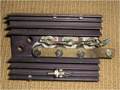
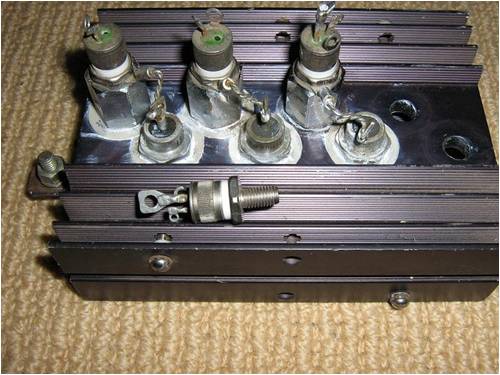
The loose one is a scr to show the size of the stud. (6mm)
There is bigger and smaller ones than these.
Pete.
Sometimes it just works |
| |
KarlJ
Guru
Joined: 19/05/2008
Location: AustraliaPosts: 1178 |
| Posted: 12:24pm 27 Jan 2010 |
Copy link to clipboard |
Print this post |
|
How about one of these puppies with 4 to spare.
http://cgi.ebay.com.au/Rectifer-Diode-130A-400V-Anode-Stud-e quiv-SKN130-04_W0QQitemZ320480301249QQcmdZViewItemQQptZAU_B_ I_Electrical_Test_Equipment?hash=item4a9e1d50c1
I have a couple of small ish heatsinks (ex PC power supply)Edited by KarlJ 2010-01-28
Luck favours the well prepared |
| |
KarlJ
Guru
Joined: 19/05/2008
Location: AustraliaPosts: 1178 |
| Posted: 01:00pm 27 Jan 2010 |
Copy link to clipboard |
Print this post |
|
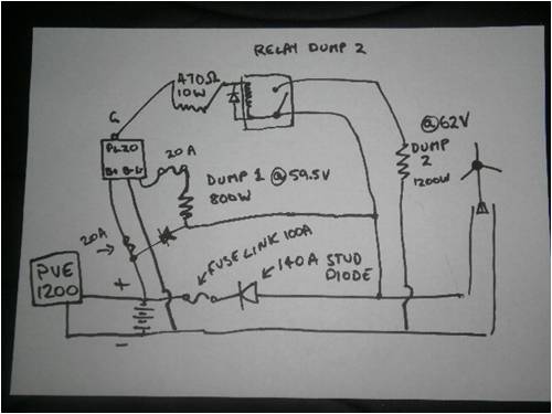
OK so within the confines of what I have (less the huge diode)
this is the schematic I propose
This gives the PL20 accurate measuring of Batt voltage
Protected by 20A breaker/ fuse
Diode keeps dumping to mill side only (at a cost of 20W!)
Dump 1 LSET=10 @ 59.5V-PWM controlled 20A fuse dump rated ~800W(dont actually know if this means it varies the switching based on how much load it needs to dump or not)
-also diode blocked to prevent breaking the PL20
Dump 2 GSET=8 @62V for alarm voltage trips relay (diode across the coil-drawn the wrong way in the sketch!) connecting dump 2 could have a fuse but no longer matters as diode blocked from battery and mill never make 1200W, even if fuse link blew would still work to control the mill
I'm happier since OZ / Pete recommended the stud diode, I could never see those little blocks doing full rated power in DC, regardless of their 35A rating.
Luck favours the well prepared |
| |
KarlJ
Guru
Joined: 19/05/2008
Location: AustraliaPosts: 1178 |
| Posted: 01:17pm 27 Jan 2010 |
Copy link to clipboard |
Print this post |
|
Actual mounting of the stud I was thinking could go on heatsink size appropriate??
Fly lead goes to mill, stud goes to sink which goes to battEdited by KarlJ 2010-01-28
Luck favours the well prepared |
| |
Downwind
Guru
Joined: 09/09/2009
Location: AustraliaPosts: 2333 |
| Posted: 01:29pm 27 Jan 2010 |
Copy link to clipboard |
Print this post |
|
Karl,
You let your daughter draw your schematics again. 
Bad luck with the stud diodes you listed a link for, they are all sold. I bought them.
Only kidding, think they would be a scoop buy.
To the point you might want to get 2 sets and do your main rectifier out of 6 of them too.
You can use the block rectifiers for your cap doubler as the current is low through that.
I made a "best offer of $5.00 ea for 2 sets, so will see if he excepts the offer only prob he dont list a postage cost.
As for your schematic why the diode up near the PL-20 ??
Give your components numbers next time so it is easy to referr to a item.
I think the heat sink you have might be a bit light and you will need a chunkier one or a block of aluimium that you can tap for the diode and tap for a bolt to mount your cable to.
Not sure which way the stud diodes listed are...Thread + or -?? as you can get them either way.
Pete.
Sometimes it just works |
| |
| |
Page 1 of 3 |
