
|
|
Forum Index : Electronics : Op-amp charge controller
| Page 1 of 7 |
|||||
| Author | Message | ||||
Downwind Guru Joined: 09/09/2009 Location: AustraliaPosts: 2333 |
I received a message requesting some help in trouble shooting the opamp charge controller. [quote] I've seen you post a few responses to the Charge Controller project using the TL084 op-amp. I have built the circuit and am unable to get it working, I know a little bit about electronics (apparently not enough). I have also simulated the circuit using Electronics Workbench *simulated it after building it* and still can't get it to work. Everything has been double checked in terms of component placement and type. Have you seen the posted version of the project working? Any comments you may have relating to the construction of this project would be greatly appreciated. George [/quote] Hi George, I will try to help if i can but some others might have more information than myself as i have not built this project. It was the clever bear Gizmo that designed this. Firstly opamps are a component i love to hate, they have given me more greif than any other component that i have worked with thus far. So i can understand you having a little problem. Secondly we all make mistakes in circuits that we can not see for the sake of looking. (unless you are dutch and named Peter  ) )
Ok let me ask you some dumb questions so as to eliminate a few possiables. 1) have you made any component subsitutes. 2) have you worked with strip board before. 3) have you cut the tracks/strips where required, there is 14 cuts to be made. 4) what voltage is your battery. 5) Do you understand inverting and noninverting pins on the opamp. The next thing to do is to give some voltage readings for the 4 output pins of the opamps, as this will indicate what is going on in your circuit. If you can answer these questions and give this information than we should be able to start to work out what is wrong. Pete. Sometimes it just works |
||||
| Bub73 Senior Member Joined: 10/12/2009 Location: United StatesPosts: 116 |
I'm building my 4th one on project board. I have substituted a hong kong volt meter instead of the power led. All worked well so far except for one faulty new TL084. I did omit a jumper on the TL084 once and it took me awhile to figure out what I did wrong. They do work nice. Bob 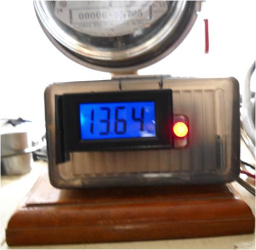
|
||||
George Newbie Joined: 07/02/2010 Location: CanadaPosts: 8 |
Hi Pete, Thanks for the post. To answer your questions: 1. No component substitutions, I ordered everything from Digikey to spec. 2. This is my 3rd or 4th time using veroboard. I have breadboarded many projects in college. 3. I have double checked the track cuts, also I have built the project a second time on a breadboard, with new components. Still doesn't work. 4. Battery voltage was delivered by a variable power supply at 12 and 15VDC. 5. I have double checked the pin outs on the TL084 and compared them with the data sheet. I'm sure at this point, judging from the responses, that I have no doubt missed something. It sounds as though many others have completed this project successfully. My simulation on Electronics Workbench looks identical to the posted schematic on the web site, only the simulation doesn't work(!). Any input on this matter would be greatly appreciated. George George |
||||
| Downwind Guru Joined: 09/09/2009 Location: AustraliaPosts: 2333 |
George, You did see the cut tracks under the opamp? Power up the circuit and give a voltage reading for each pin of the opamp. Can you post a photo of the top and bottom of the board. Have you checked the resistor values with a multi meter to ensure you dont have something like a 22k resistor instead of a 2k2 resistor etc. Pete. Sometimes it just works |
||||
| George Newbie Joined: 07/02/2010 Location: CanadaPosts: 8 |
Hi Pete, My board layout is different than the one posted. I have pictures here to post of my prototype but before I do, perhaps you could help me figure something out. The posted picture of Gizmo's vero board layout shows pins 1 and 8 on opposite sides and opposite corners of each other on the op-amp. My attached photos show the manufacturers pin outs as being on opposite sides but on the same end of the IC (if 7 is bottom left, then 8 is bottom right). I realized this might be a mistake on the posted vero board layout when I started comparing the schematic to the vero layout. Am I missing something or is the posted vero layout incorrect? Before I start posting all my pics, I thought this might be a good starting point for my troubleshooting. Thank-you for your help so far, I look forward to your response. Georg 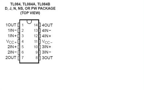
George |
||||
| George Newbie Joined: 07/02/2010 Location: CanadaPosts: 8 |
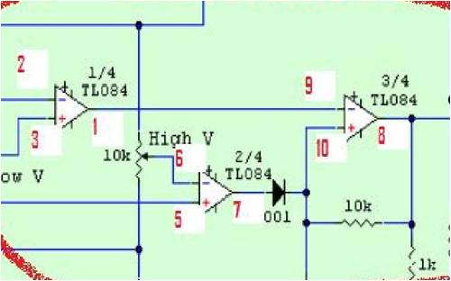
Just to add to my previous post, I have attached a copy of the schematic and have added the op-amp connection pins to it. When compared to the vero layout the pin outs just don't make sense to me. 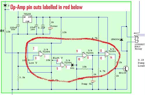
George |
||||
| Bub73 Senior Member Joined: 10/12/2009 Location: United StatesPosts: 116 |
Maybe this will help; I think you got it numbered upside down looking from the top side. Pin 1 should be the first pin on the left near the red arrow in your first pic. 
I could be wrong lets see what Pete has to say. Bob |
||||
| Gizmo Admin Group Joined: 05/06/2004 Location: AustraliaPosts: 5185 |
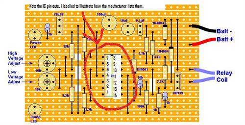
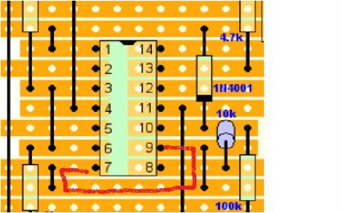
The veroboard is definately correct. I think you've come across some bad manufacturer data or are looking at the pins from the underside of the chip. I've added the pin numbers to this copy... 
This is looking at the component side of the veroboard. the copper tracks are on the other side. Below is a photo of the working circuit while I was prototyping it. I've marked the IC pins. Note the IC legs are facing down, away from you. The IC is in a socket in this case. 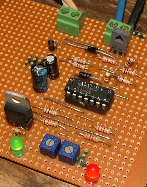
Let us know how you go. Glenn The best time to plant a tree was twenty years ago, the second best time is right now. JAQ |
||||
oztules Guru Joined: 26/07/2007 Location: AustraliaPosts: 1686 |
Perhaps for completedness, you should fix the DB139 to BD139 on the veroboard picture also. ..........oztules Village idiot...or... just another hack out of his depth |
||||
| Gizmo Admin Group Joined: 05/06/2004 Location: AustraliaPosts: 5185 |
Now your just been picky
Thats done. Glenn The best time to plant a tree was twenty years ago, the second best time is right now. JAQ |
||||
| Downwind Guru Joined: 09/09/2009 Location: AustraliaPosts: 2333 |
Talk about confusion!!! If you are not confused, i am!! Gizmo is correct with his pinouts. If you follow the schematic you cant go wrong, it will make no difference which of the 4 opamps in the package is used in what order as long as they are used in sets. The reason i asked for a photo was to see what you have used where to solve some confusion. I think it could be handy if Glenn also numbers the schematic pins as you have done, it will make construction easier for the novis and trouble shooting easier for the rest of us to referr to a pin in text. If you have wired the board as you have labled the schematic it should be correct if you have worked to the pinouts as per the diagram that Bob posted, which is the same as Gizmo posted on the main page. Pete. Ps:- post a photo so we can see what is going on regardless of how you layed the board out. Sometimes it just works |
||||
| George Newbie Joined: 07/02/2010 Location: CanadaPosts: 8 |
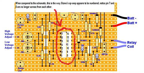
Great, I understand now about the vero layout. The first op-amp in the schematic is labeled 1/4, should that not correspond to pins 1,2 & 3 on the TL084 (labeled output 1, input 1-,and input 1+). On Gizmo's post the actual vero wiring in this case would be using op-amp 2, where the schematic says 1. Right? To try and explain better I have added Gizmo's pic, you can see that pin 7 and pin 9 are connected on the vero (connecting op-amp 2 output to op-amp 3 input). On the schematic it shows op-amp 1 or 1/4 feeding op-amp 2 or 2/4).None the less, right or wrong about the op-amp labeling, Pete is right it should still work. 
George |
||||
| George Newbie Joined: 07/02/2010 Location: CanadaPosts: 8 |
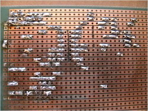
To add to my last post here are some photo's of the board. I apologize for any problems with resolution and will gladly re post upon request. I have toned out connections, as I am aware that my soldering may not be the best. Excuse the messiness. Please let me know if anything looks out of place. 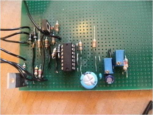
George |
||||
| Downwind Guru Joined: 09/09/2009 Location: AustraliaPosts: 2333 |
Hi George, Gizmo has caused a little confusion between the vero board lay out and the schematic. He has swapped opamp 1 and 2 around between the two diagrams, this should make no difference to operation if you had followed either one of the layouts but if you swap between the two then an error is easy made. Looking at the bottom of your board there looks to be some heat stress on some of the tracks that would imply to me some short circuits on the board.(maybe some solder bridges between connections) I can only count 12 cut tracks on your board and think there should be 14. (this might be due to how you wired the board) Is there any reason why you did not follow the vero board layout that Gizmo has given. Is that 2 different boards we are looking at in the photos as things dont look to match up. Pete. Sometimes it just works |
||||
| Bub73 Senior Member Joined: 10/12/2009 Location: United StatesPosts: 116 |
I can't follow them either, see if you got the basic voltages present I laid out in the image below. I hope Gizmo doesn't mind what I did with his image. 
Its late here I'll check back in the morning. Bob |
||||
| Downwind Guru Joined: 09/09/2009 Location: AustraliaPosts: 2333 |
Hi Bob, I dont think Gizmo will mind at the slightest, its good to have you involvement....Your image works for me. A schematic dont always follow pin for pin to a circuit layout unless the schematic pins are labelled. In this case its created a little confusion i think. Those of us that post a circuit and the layout image, spend a lot more time to create the screen images and data to go with it, than the time it takes us to build the circuit in the first place. We spend a lot of time to get it laid out so anyone should be able to copy it. It becomes a problem when the constructor makes layout changes and it dont work afterwards. Or has a constuction fault. (solder bridge etc) Considering others have built this as per the vero board layout and it has worked, than one can only assume a construction fault. We need to work out where. I will build this circuit when time permits and post voltage readings for all the opamp pins so the constructor can check their board against the readings to isolate the fault reigion...unless someone with the circuit already built cares to do it first. George, If you have a multimeter stick the neg lead to neg on the supply in. With 12 volts on the input take a voltage reading for every pin on the opamp and tell me what you read per pin.... every pin!! How many opamp chips do you have? Pete. Sometimes it just works |
||||
| Tinker Guru Joined: 07/11/2007 Location: AustraliaPosts: 1904 |
George, I notice on your veroboard you appear to cut the tracks with a knife or something similar. There is a *much* easier way to do that, simply use a small (~3/16") twist drill in a small chuck and turn it in the hole of the copper track a few times by hand!. This will cut the track quickly and neatly. Actually, there is a small tool available which looks like a drill bit in a plastic handle - best thing I ever got for tinkering with vero (strip) board. Klaus |
||||
| George Newbie Joined: 07/02/2010 Location: CanadaPosts: 8 |
Pete & Klaus, Thanks for the tips, I think I'll spend the evening rebuilding this thing the way Gizmo has laid it out. I know I can do a better job soldering and cutting the tracks. Pete, after the rebuild if it doesn't work (again) I'll send you voltage readings pin for pin. I'll post back soon with pictures and results. A big thanks to everyone for the great support. This is absolutely the number one site and forum I have found on home built renewable energy projects. George George |
||||
| Downwind Guru Joined: 09/09/2009 Location: AustraliaPosts: 2333 |
George, If i build one of these circuits and get it to work before you do you owe me a $ dollar. >>>>pete considers ...exchange rate = profit  , less exspence = loss , less exspence = loss  >>>> >>>>
If you follow Gizmo's mud map you cant go wrong, Its basically X&Y co-oords on the vero board. Remember 3rd time lucky.. Pete. Sometimes it just works |
||||
| Bub73 Senior Member Joined: 10/12/2009 Location: United StatesPosts: 116 |
Pete; I'm building my 4th now all on different smaller boards and have used the vero board layout for all without many problems except space. I'll try to get some pin out data when I test it sometime next week. I'd post some pic's but the different smaller boards with the hong kong meters may only add to the confusion here just now. Bob |
||||
| Page 1 of 7 |
|||||
| The Back Shed's forum code is written, and hosted, in Australia. | © JAQ Software 2026 |
