
|
|
Forum Index : Electronics : need help with piclog shunt
| Page 1 of 4 |
|||||
| Author | Message | ||||
niall1 Senior Member Joined: 20/11/2008 Location: IrelandPosts: 331 |
at the moment i,m building the piclog logger circuit...the board is finished and i,m starting to think about making the anemometer whitch is a lot of fun however the shunt i,m still a bit confused about...accessing the .1r resistor is a bit expensive here so far so i,m wondering about using stainless allthread in its place the stainless would need to be calibrated in some way and heres what i was thinking off doing 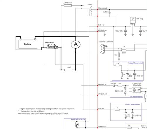
the diagram isnt that clear but i was hoping to put a load on the battery with an ammeter in series then watch the reading ..at the same time the allthread could be adjusted to let the pic come into line with its reading ? i,m not much good with ohms law so would this work ?....it might make a cheap shunt from recycled stuff .. 
niall |
||||
oztules Guru Joined: 26/07/2007 Location: AustraliaPosts: 1686 |
You only need the amp meter, the load as you describe, and a voltage meter across the all thread. For a given current, your voltage drop will be a product of the resistance across the allthread. So, if your load was say 5 amps, then you adjust your allthread to have E=I X R or .1 X 5 = .5 volts. So adjust the all thread to give you .5V and you will have your .1R resistor.(keep an eye on the amp gauge and calculate accordingly if it moves at all while you adjust your allthread) Or if the load was 1 amp, then the voltage drop across the allthread when at .1R will be .1V etc etc. EDIT: I use the PC supplies I have converted to give me set current, so it makes no difference if I change the load, current will remain the same.... much better for this calibration..... ..........oztules Village idiot...or... just another hack out of his depth |
||||
Downwind Guru Joined: 09/09/2009 Location: AustraliaPosts: 2333 |
Hi Niall, Just one thing to add as Oz has given you a setup method. It really wont matter greatly on what the calibration of the shunt is as long as at maximum amps the voltage dont go higher than 4.5 volts, it can be lower but not higher. The max. voltage needs to be lower than the rated voltage of the zener. The actual calibration is done in the piclog software so it dont matter what the shunt calibration is. The picaxe will convert the shunt voltage to a digital value that will have little bearing on the shunt voltage any way, other than a linear digital value up and down in respect to the shunt voltage. You might find the the value from the picaxe will fluctuate as shunts are a rather noisey device. To calibrate piclog all you need to do is take the input value shown in the calibration window and divide it by the actual amps shown on your meter, the value of this is what you need to enter into piclog in the calibration box. Pete. Sometimes it just works |
||||
| niall1 Senior Member Joined: 20/11/2008 Location: IrelandPosts: 331 |
ok.. 
that all looks promising ...i,ll try the simpler method of calculating the v drop and then look at the pic software adjustment ...i just want to play with the piclog for now till me and it get to know each other better.... cash is tight ....so the wardrobe will be suppling a lot off stuff for now the anemometer seems a nice starting point 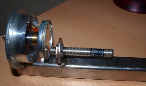
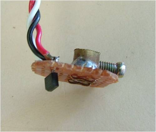
its just an old video head assembly with a prox sensor tagged on underneath 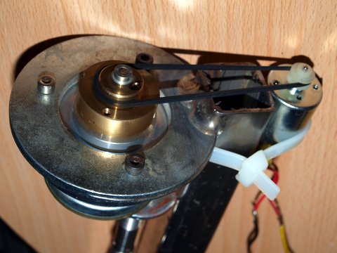
testing the pulse stream seems (i think) encouraging ..i can run it fairly low rpm its a lot of fun niall |
||||
| oztules Guru Joined: 26/07/2007 Location: AustraliaPosts: 1686 |
When I saw the rubber band I panicked.... but it is only for testing... You can cut slots in the wheel to increase the pulse stream, and lower effective rpm limits. They are handy little gadgets. (may have to decrease gap width a bit for better sensitivity for more gaps). What cup arrangement do you envisage for this project? ...........oztules Village idiot...or... just another hack out of his depth |
||||
| Downwind Guru Joined: 09/09/2009 Location: AustraliaPosts: 2333 |
I have built a few of these now and find you really need around 30 or more pulses per rev to have something that will read worthwhile in any thing less than a cyclone. Although if your targets/pulses is spaced very evenly apart then you can use a "pulsin" command (instead of count)and time the interval between pulses to get a accurate count with low pulse rates per rev. Nice work. Calibration is the hard part, unless you can borrow a bought 1 to work out the wind speed from. Pete. Sometimes it just works |
||||
| niall1 Senior Member Joined: 20/11/2008 Location: IrelandPosts: 331 |
i have absolutely no idea... a trip to the euro bargin shop i,m hoping will solve that dilemma... 
i,m kind off getting emotionally attached to the video head...its got 2 nice little nsk bearings in it and is beautifully balanced a baby savionius with thin sections of plastic pipe might be fun if the kitchen section doesent provide 3 candidates keeping the water out will be an issue although this one is partially naturally protected with the bearing layout edit...mmmm...Pete i have 10 sections above the sensor at the moment if the senser can cope with a higher Hz rate i could add more i think by changing the layout fairly easily with a slightly bigger disk on the bottom and tighter pattern niall |
||||
| Downwind Guru Joined: 09/09/2009 Location: AustraliaPosts: 2333 |
The first one i built i used the dome caps off some roll on deodorant. You have just missed the anaometer cup stock sales for this year. (Easter egg molds) I find them light and cheap, and if needed to be replaced it only a small cost as i have a bag of them left over. With a larger hub as you have i found 4 cups worked better but others say 3, to me 3 is ok if you have a small hub and can keep the cups in close. My cups are at about 250mm dia.(125mm radius) I used a vcr head for the first one too and they have great bearings as you say, the only draw back is the weight of the head, and this will come into play but not enough to to effect things greatly. You will be supprise just how slow it will spin on average and is why you need the higher target count. If you search back about a month in the threads you will find a thread i think was called "aneometer build time" that i posted some pictures to and there is some more information in it as well. I added a cheap 433mz transmitter to mine and pick the data up wireless inside the house at the pc. If you need any help with setup or would like to play with wireless, than ask as i dont mind helping if i can. Pete. Ps:- the sensor can cope with a higher Hz rate than you will ever be able to generate here. Sometimes it just works |
||||
| Gizmo Admin Group Joined: 05/06/2004 Location: AustraliaPosts: 5185 |
I built one recently using a motor from a old dead hard drive and a hall sensor from a dead PC fan. I used the magnet hub and bearings, discarded the stator, replaced it with a hall sensor. The magnet hub has 6 ceramic magnet poles, so I get 6 pulses per revolution. Its very ugly, I never meant to show anyone. 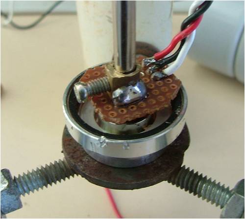
The hall sensor has 3 wires ( some have 4 ), 2 for power and one is output. Below is the finished aneometer and wind vane. My cups are just PVC pipe cut in half, not as efficient as full cups but it seams to work OK, the bearings are good so its starts up in light winds. 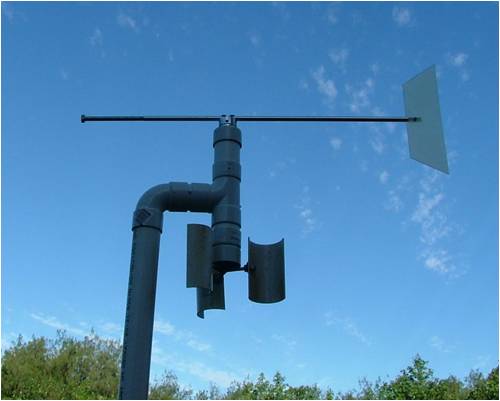
Glenn The best time to plant a tree was twenty years ago, the second best time is right now. JAQ |
||||
| niall1 Senior Member Joined: 20/11/2008 Location: IrelandPosts: 331 |
hi Glenn .... looks good to me...  ...if i can finish up with something that looks as functional as that i,ll be happy...i think i,ll try the paddles as well ...if i can finish up with something that looks as functional as that i,ll be happy...i think i,ll try the paddles as well
Pete... i went back over the thread and seen that you could solder onto the platter so i,m changing over to using that as well , i think i can leave out the flywheel head section now and mount the platter with holes drilled around it to trip the senser getting the most out of this particular sensor like Oz commented seems best know ...one platter might just be needed i,m interested in the wireless link ...i,ll try to get all the nuts and bolts bits out the way first lots to think about niall |
||||
| niall1 Senior Member Joined: 20/11/2008 Location: IrelandPosts: 331 |
just to erm..recap on this 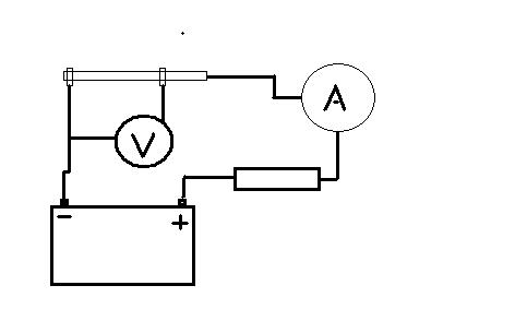
say i set up the circuit above with a load that happens to give 5A draw (it,ll probabely be a bit different but not much) so v = 1*r...12 = 5 * ? so ? or r must be 2.4ohms ...something like a car headlight i,m looking for about .1r shunt so ...5 by .1 is .5 drop so the meter should read .5v in the diagram ? also if i,m reading this right it doesent matter if the supply is 24v ...as long the voltage drop reading is a product of the amp reading and shunt resistance required ?  niall |
||||
| Downwind Guru Joined: 09/09/2009 Location: AustraliaPosts: 2333 |
I dont know if its a typo but this is wrong [quote]so v = 1*r...12 = 5 * ? [/quote] It should read .....V = I x R......or.... volts = amps x resistance Also your circuit above is wrong to, where you have the wire from the amp meter going to the allthread end is wrong, and needs to be moved to the same point the volt meter is connected to, or adjusting the allthread nut will have no effect. Correct this then.............. Look at it this way, connect you "R" being a car headlight or what ever and take a reading of your amp meter, now adjust the nuts on the allthread till your volt meter reads 1/10 of the amp meter value. So if your amp meter reads 6.4 amps adjust the allthread till the volt meter reads 0.64 volts. As OZ said above then check the amp meter again and if it has changed slightly readjust the althread till the 2 match. The aim is for the volt meter to read 1/10 of the amp meter. (at 10 amp the volt meter will read 1 volt) This will allow you to read upto around 30-40 amp in piclog as the zener diode will start to conduct at much less than the 4.7 volt rating, and personally i dont like the circuit for this reason, and think you will find it not acurate as the amps increase. Pete. Sometimes it just works |
||||
| GWatPE Senior Member Joined: 01/09/2006 Location: AustraliaPosts: 2127 |
Hi Niall1, The shunt as used in the original piclog project, and calculated out at say 0.1 ohms as you are going is OK for high voltage, low current applications, but for a 12V system, you can surely see the problem with power lost, just to measure the current. I raised this a few years ago, and don't remember all of what was said. I could not justify wasting 10W out of every 120W at 10A, and 40W out of 240W at 20A, just to measure current. You need to get a higher sensitivity current sensor. The sense element [shunt] should be at least an order of magnitude lower resistance, and this will require an amplifier to make better use of the ADC input on a micro. I would use a shunt with low temperature drift, and it would have a sensitivity of around 50mV for 50A. This will require an amplifier with a gain of about 100. This is a classic case for justifying a different sense element, like a HALL effect curent sensor. These can't be made from scrap though. Gordon. become more energy aware |
||||
| niall1 Senior Member Joined: 20/11/2008 Location: IrelandPosts: 331 |
thanks....stuff dosent usually sink in very quickly...
edited diagram 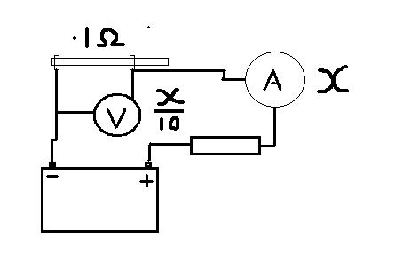
should be able to try it out this week niall |
||||
| niall1 Senior Member Joined: 20/11/2008 Location: IrelandPosts: 331 |
hi Gordon sorry for the double post here..i dropped in to what Pete said after your reply for now its a learning curve about ohms law....its interesting to hear how the shunt could be fine tuned ...i see lots of cheapish very low r block type shunts on ebay erm ....i,ll leave that stuff to you guys... ...mmm....i wonder could this be based on a single op amp circuit.....or is that a simplistic view
edit ....heres my disjointed thinking...a small microphone or guitar pick up produces a very small Mv output this seems easy to amplify to a much higher v...could the same be applied to a low shunt v output ? maybe i should have stuck to the music....  niall |
||||
| niall1 Senior Member Joined: 20/11/2008 Location: IrelandPosts: 331 |
kind of finished the anemometer copying off the work done by others on previous threads , 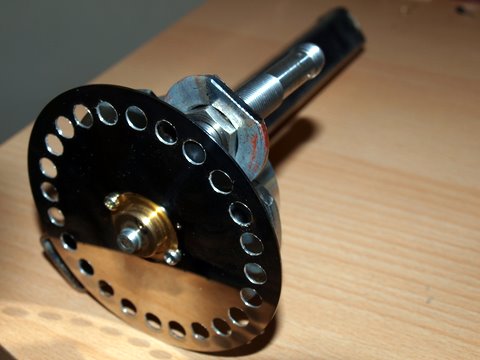
i wanted to use the paddle type arrangement but a last minute look around the local toy store produced some "comet balls"... not to be confused with the "led balls" on the shelf above if your a kid.. the mind boggles... the cable run is very long ...so i tested the signal back to the pic at 12v and it seemed ok , i can put a medium led on it and watch it pulse away i think it,ll run the extra 10m to get it up on the the mill mast ... 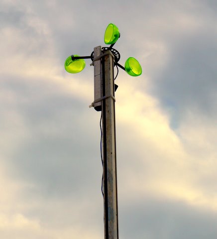
i,m waiting on a cheap handheld anemometer from ebay ..in the meantime i,d really like to hang out the car window with it and do some basic tests which could be a lot of fun niall |
||||
| Downwind Guru Joined: 09/09/2009 Location: AustraliaPosts: 2333 |
You say 12 volt back to the picaxe??? I hope you are not feeding 12 volt into the picaxe pin. 
You will need to reduce this voltage to no greater than 5 volt input to the picaxe. Good to see you have the project up in the air. Pete. Sometimes it just works |
||||
| VK4AYQ Guru Joined: 02/12/2009 Location: AustraliaPosts: 2539 |
Hi Miall Nice job mate I am a bit curious as to how you got such a high voltage. Before you put it up it may pay to give the plastic cups a few coats of silverfros paint to retard the UV degradation a bit as they may not be UV resistant plastic. All the best Bob Foolin Around |
||||
| Downwind Guru Joined: 09/09/2009 Location: AustraliaPosts: 2333 |
Hi Bob, Niall used a off the shelf proximity sensor and most of these work on 12 -24 volt, so i am guessing it is why his signal voltage is 12 volt. Pete. Sometimes it just works |
||||
| niall1 Senior Member Joined: 20/11/2008 Location: IrelandPosts: 331 |
hi Bob/Pete i dont know much about these sensors but as far as i can see they output a signal of equal v (or close) to whats supplied possibly even enough to drive a small relay (but i,m not sure about that ).....this signal goes to the opto coupler through the matching resistor on the pic cct 
the cups are soft plastic alright and mightn't even keep their shape very well , as well as degrade so a couple off coats would be a good thing calibrating to a happy medium is the next learning bit ....it does seem to spin in very low wind and i,m also appreciating now that cup anemometers arnt speed merchants as well... ..all interesting niall |
||||
| Page 1 of 4 |
|||||
| The Back Shed's forum code is written, and hosted, in Australia. | © JAQ Software 2026 |
