
|
|
Forum Index : Electronics : need help with piclog shunt
| Author | Message | ||||
niall1 Senior Member Joined: 20/11/2008 Location: IrelandPosts: 331 |
as far i can tell so far using allthread is practical for low Mv shunts..I havent had much luck trying to calibrate a piece for .1r ...it seems to need to be very long stainless steel wire wrapped around a former might be more pratical for .1r i found this measurment/guide on another site a 1mm by 1mm rod of stainless steel 1 meter long would have a resistance of 0.74 ohms. i did find this cct which seems to amplify a .01r shunt to match a pic chip 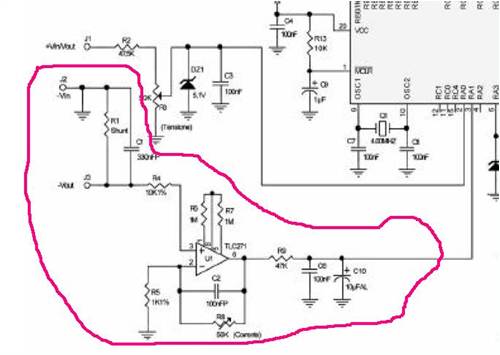
it seems to use a tc271 to match the shunt...dont know if this will work but i went ahead and ordered a few anyway this is the pdf of the cct (its not overly big)....erm i,ll need to brush up on the Italian though... 
2010-06-15_225001_mk3980.pdf niall |
||||
Downwind Guru Joined: 09/09/2009 Location: AustraliaPosts: 2333 |
Hi Niall, Why do you need to use a shunt in the first place. Are you able to access the Ac side before the rectifiers as i feel there is a much better way to measure the current than through a shunt. There is other chips available that work well with a shunt and picaxe but feel they are a last resource and are rather costly. A shunt as you have been trying to use is not very accurate as it will change with temperture. Have a look on fleabay for shunts if you must use one, as they are cheap and in some cases you can get a meter with them for a little extra. Dispite the good intensions of some with the idea of building your own shunt i think it is a waste of time and will give poor results. If you are going to go to the trouble of logging current then you need something that is reasonably accurate to start with. Threaded bar or wound wire just wont cut it. Pete. Sometimes it just works |
||||
| VK4AYQ Guru Joined: 02/12/2009 Location: AustraliaPosts: 2539 |
Hi Niall In the past I have used a strip of stainless steel to make a hi amp shunt as you can move a clamp along the strip until you get the reading you want, but as Pete suggests a shunt from ebay with meter and all for $25 is a good way to go. I am not to sure of the linearity of the shunts though, as the ones I have tried have heating problems at high amps as would any resistive shunt. OK as an indicator but if you want accuracy across the range I found it better to go for a higher reading meter say 100 amps and read the first 50% of its range, after that it gets a bit suspect. Ac current transformers would be OK but unless modified circuit is used are going to read one phase only so all readings need to be X 3 but as Pete said earlier that can be written into the PICaxe as part of the code. 
Just a thought Pete, would it be practical to use the wire from the rectifier to the battery as a shunt as it would have some slight voltage drop relative to the current flow, and that would save including another resistance in series and introducing more losses than you already have. All the best Bob Foolin Around |
||||
| Downwind Guru Joined: 09/09/2009 Location: AustraliaPosts: 2333 |
To start with shunts in the low side (negative) is a bad practice i think as it creates ground problems with other monitoring systems. To me the ground should have the least interuptions in the circuit as possiable. High side monitoring needs a chip that can handle the line voltage and keep the signal output to no greater then 5 volts full scale. There is no reason the wire it self could not be used if it was long enough to give enough resistance to allow for sensitive monitoring.(back to square 1...Resistance) The other problem is long resistive cables introduce a lot of noise into the readings. I would think using a calibrated shunt would be far better and give much better results. Working with crap and expecting good results is just not going to work in my books. Do it right and it will cost far less in the long run, as well you will have results you can actually work with. I am currently testing some chips dedicated for this purpose, with good results, but until they are proven to work reliable and accurate i see no further point in discussing them as it only creates others to go down this path and might be a waste of time and money for them. Also they are smd and less than half a match head in size, so possiable not what the averege home constructor is able to work with. Pete. Sometimes it just works |
||||
oztules Guru Joined: 26/07/2007 Location: AustraliaPosts: 1686 |
I tend to think we have used shunts to measure currents for the last hundred years or so, and there was no reason to think that they were or are crap.... that's a little bit over the top I feel..... even got to the moon without pics. We are after all, only talking about pic log measurements, and they are time slices only, and may not be high accuracy to the real world. What happens between the slices is ignored, and averaged I suspect... and fair enough too. The problem with temperature compensation is a purist argument, and not relevant to mills, they change continuously, and if the resistance is low, should not be problematic to this kind of exercise. Bob, I tend to agree with the use of using the wire itself as the resistance, and used this on my battery leads on the car to register the current in and out of the battery.... that wire is 1/2" thick copper, about 18" long.... not a lot of resistance.... particularly when most here will experience less than 100A Pete, I am happy to put the shunt in the negative leg, and do so in my PSU conversions. I fail to see how they affect any other measurement, when we are talking microvolts in a lot of cases where we amplify as Niall has suggested. (I do that too in the PSU conversion, and it seems to keep tight control of 50khz systems, living on the edge of extinction with each cycle. There is no room for failure here. It does not seem to cause problems with the voltage regulation, all it does is establish a new negative... some microvolts away from where it would have been. All referencing in those circuits will be from that point on. I fail to see any problem with designing around that proviso. The real resistance that causes problems is in the stator and wiring run.... temp, armature reactance etc etc. A single turn extra on the stator will have more effect voltage and resistance wise than a decent shunt Until I see different, I will trust a S/Steel threaded bolt shunt with a analogue meter over any electronic solution that may not compensate properly for wicked harmonics that get generated from the diode block..... and more so at high current..... and filters skew the results... maybe frequency compensation as well here for the filter bandpass. Using the magnetic field and measuring that will still have the noise, as those spurious spikes and harmonics still generate magnetic interference to your transducer.....unless it measures so slow as to miss them..... so what were you measuring again?? Interesting, perhaps you may not see the PF problem here??... ie VA is not necessarily watts, and I'm not sure what that means to magnetic field - current measurements in systems with poor PF. The hash in that signal is real filter territory..... and your non-linearity (diode) can be problematic here..... hmmm...sometimes an analogue solution is still good. I'm being a bit harsh here, but if you do not compensate for everything, then your results will be subject to the garbage in garbage out. syndrome..... a synthetic figure if you will. The moment you simplify a system to make calculations simpler, is the moment you start to leave reality..... weather bureau springs to mind here. Or is close enough good enough............
I don't know what system you are currently adopting, as your oblique reference to it's operation tells me little of how to interpret your argument, or in fact what you are suggesting as an alternative.... but if it is an average of time slices in a highly dynamic system.... you'll only be close at best. If it is a bunch of time slices in a dynamic system with a line of best fit.... ditto. And if you can measure the wind accurately..... I will be very very surprised indeed. I tried three commercial ones within feet of each other.... and they were all different. They all exhibited different inertial characteristics, different sampling rates and different wind speeds, as the wind changed all the time, they ran amok all the time. A steady wind may have been different..... but that does not seem the nature of wind. This kind of logging is not going to change anything, but will provide a base line for further fiddling. If fiddle one does better than fiddle two, then it is probably better, but the wind speed will render it useless from an absolute perspective, so whatever bias is built into the system via shunts or whatever, providing they are linear in nature, should not affect the overall picture. A calibrated shunt is no better than a sensible shunt, unless you are doing very sensitive work...... this aint that.... it's just a windmill with time slice voltage, time slice current, time slice wind speed, in a highly dynamic system....
A grubby little shunt has seemed to have served the world fine up till now.... perhaps it still can. .............oztules Village idiot...or... just another hack out of his depth |
||||
fillm Guru Joined: 10/02/2007 Location: AustraliaPosts: 730 |
I agree completly with what Pete has said , spend a bit of cash and do it right and you will have a reliable logger . I origionally used the shunt / resistor on the neg , one of the main problems it created was raising my battery voltage to high which in turn caused my dump load to come on , loosing power through the shunt and dump load & not to mention damage to the batterys. I spent arround $40 to buy the allegro sensor and problem is solved , and the ones Pete is using that measure on the Ac sound even better. PhillM ...Oz Wind Engineering..Wind Turbine Kits 500W - 5000W ~ F&P Dual Kits ~ GOE222Blades- Voltage Control Parts ------- Tower kits |
||||
| Downwind Guru Joined: 09/09/2009 Location: AustraliaPosts: 2333 |
My point being for $10.00 off fleabay you can buy a calibrated shunt of a rated amp range to suit your needs. Threaded bar and nuts and other junk to make a dodgie shunt will more than likely cost you more than that. In Oz own words ....Garbage in equals garbage out..... Yes i can make a shunt that will work and you can too Oz, but not all are like us so why bother when for the same money you can get something that will work out of the box. (its still using your grubby little shunt) As i said above i am playing with some dedicated chips for reading a shunt for use with those who need to read the DC current and not the AC (like DC with solar for interest) If they prove to be as good as they first test to be, than it will solve a lot of problems. They need a good steady mV known range and to expect to use a dodgie shunt is asking for problems right from the start. I would think it better to guide people to a better product that they can add to later without the need to purchase a whole new system. I doubt we went to the moon with allthread shunts (well the Russian maybe) and diode noise is a big problem with current measuring on a windmill and needs filtering to reduce it. I am all for home brew stuff but there is some things that is just not worth the ass ache of going down that road, as it can get costly in the long run. Niall has already commented the lack of success with his shunt and may end up as time and money wasted for him. Yes it will always be time slices with budget end logging and the information gained if still far better than glancing a a meter in huge time slices. Pete. Sometimes it just works |
||||
| niall1 Senior Member Joined: 20/11/2008 Location: IrelandPosts: 331 |
thanks for the replys and info ..the shunt is a bit on my brain at the moment... 
there seems to be lots of variables and a knowledge of instrumentation electronics would help ...but thats beyond me........ i know it,d be better to buy an off the shelf shunt but i dont even know if the amp will work...
the opamp seems to be the crucial bit....not as much the shunt ? there seems to be lot off shunt variations and using Bobs idea off keeping away if possible from the limit seems interesting maybe it,l be possible to test it out using stainless at low power ..then get the low drift commercial one i,m using (gratefully) the piclogger as a learning tool...it does push you in that direction off putting a pen to paper and trying to work out wattage loss , voltage drop etc....so for know i,ll stick with a simple shunt...hopefully the lowest resistance thatl work with amplification ,...if it dosent work it,ll only have cost the price of the few opamps i,m using which isnt really that bad.......if i go to buy i might understand what suits my wants a little better then..... if i can get reasonable performance with as little loss thats reasonable that,l be ok for me ..a little extra line resistance might possible help anyway as at 48v breaking stall is sometimes an issue (my mill has its builders finger print in there a bit) ps...just an ammendment to something i posted earlier...the resistors i,m using for the 48v sample v are know 47k and 2k2 metal film with a 100n decoupler and no zener i know this has been discussed in the past and is a moot point but i,ll let it run this way for a while ,dont know if this is right but i cant resist poking the thing...
niall |
||||
| Downwind Guru Joined: 09/09/2009 Location: AustraliaPosts: 2333 |
AS for you voltage divider combination, i use the same arrangement for 48 volt system but have a 27K resistor where you have a 47K resistor. So i see no problem with your setup except your values from the picaxe will be lower than mine and thats just a need for a different calibration factor in Piclog. It should work fine. Pete. Sometimes it just works |
||||
| VK4AYQ Guru Joined: 02/12/2009 Location: AustraliaPosts: 2539 |
Hi All I checked the voltage over my inverter negative lead, it is 48 inches long welding cable rated at 500 amps and gave a .02 volts drop at 200 amps draw at 26 volts system voltage and it was stable in voltage readings that increased across the range from 50 amps up to 250 amps, couldn't get any change from ambient temperature in the conductor over a five minuet test at 200 amps with digital probe thermometer. DVM readings, tried a analogue meter as well and it was more stable in reading due to not switching characters as in the DVM Cable ends are soldered to avoid diode effect in crimped terminals due to oxide film between strands of the conductor. Not saying its the best Hi Tech solution but it works without introducing any other links into the chain, I put the cro on it and didn't get any measurable noise other than background from the inverter, which I would assume you would get from anything connected into the circuit while it was active, I connected it to a earth stake 3 foot of copper driven into the ground as a lightning earth for antenna and it reduced he induced noise slightly. All the best Bob Foolin Around |
||||
| oztules Guru Joined: 26/07/2007 Location: AustraliaPosts: 1686 |
Phill, I'm surprised the batteries knew they were a few volts above true ground, and I would have thought you would hook up the dump load to measure the terminal voltage... not the terminal plus shunt voltage. Your problem, not the systems. The losses were due to you not using a much lower shunt as Niall is suggesting, and a 10c op amp to drive the output.... . or better still, just using the last part of your battery "in" lead as the shunt (as outlined by Bob above). No introduced resistance, an amp and a pi filter. No cost and bullet proof. Temperature drift will not be a problem... probably more stable than a calibrated unit as the thermal inertia is much greater. I do have 2 mills that have put out over 70A each, and over 5kw each. I know what current is, and I know how to throw a few "dodgy" shunts together. They are very effective. They don't interfere with terminal voltage measurement, and the electronics I have built to automate the system. Same in the electric car for the 300amp meter. I could have bought an off the shelf pretty meter for lots of bucks.... but I would rather the one I built from one from an old battery charger from the tip with a 50 amp scale. (X10) (It too uses one of the batt leads as the shunt... no extra losses.) Knowing it is above ground, just means a new frame of reference, and is not a reason to hook your dump load reference up wrong and cook your batteries.... thats careless. (thats why I call it terminal voltage... you can't fail then) Pete, Your correct, we can both make shunts.... or use the in circuit wires/cables On a DIY site.... thats what we should do. It is slowly becoming apparent, that we shouldn't try things anymore, we should just buy them. We shouldn't build our alternators anymore, we should just buy them... why try and build one... that would be fun. We shouldn't make blades anymore so we can understand how they actually work, and improve them as a hobby.... we should just buy them. We should worry that it takes us umteen attempts to build a shunt that works the way we want it...... why. If you take out all the trial and error, and the "make it from what you have bit", you have a simple site that just discusses products that can be bought... wow how silicon chip! Now there are a lot of ways to surmount problems that crop up from time to time, and this is the place for them to be tried and shared.... thats a shared hobby.... not an end, but an entertaining, and enjoyable means to an end. None of this is really rocket science, but it has a lot of nuances, that need help from those who have been there before. Now we can buy a system ready made and off the shelf, or we can build it. Ebay is where you can buy all of it off the shelf..... here is where you can learn to build it, and ask questions about how to. Niall has persevered with his projects over a period of years, and from what I have seen, tried most things from alts, to blades, to towers, to wiring... dump loads pic loggers.etc.... even chainsawn blades (and very nice too) He could have had these things in a week off the shelf.....or over time, built up the skills to make them in a week.... (know which one I want) start to finish. I hope he uses a home brew shunt or home brew current measuring device out of scrounged up bits and pieces. I hope he gets it to work as he wants. It will then be his to look at and see something in it more than a hole in the checking account... and he will know why it works, how it works, and just as important, what does not work, and why. Thats what this site is supposed to be about, but I'm beginning to think that I am just a dinosaur for thinking this. From a purely electronic point of view Pete, you may be right, but after fixing a lot of different pwm systems lately, it seems that there is still nothing wrong with op amps doing the thinking, rather than dedicated pwm chips or pics. For all the frills and high tech in the modern pwm chips, they don't seem to do any better in practical applications than discrete circuits..... they all fail... the last 11 were micro controller H bridge types 200Amps. Failure rate of around 20% in the first year on that particular brand of machine. So not just Niall is having trouble with micro's reading current (in truth, I suspect it has a bit more to do with the regenerative braking pulses .... but.... ).
When the wind is blowing, and the bigger mills we play with are pushing out their 100kw+..... we use "ole fashioned" shunts to measure the current..... seem to have worked for over quarter of a century. I will leave it alone, I hope you get it sorted Niall.... DIY style. If you finally give up, I guess Pete has a solution in the wind (and I have no doubt it will be good) off the shelf from the sounds of it.... but I'd stick at it.... I'd want a solution I can build from as scratch as possible.... it's a Scoraig wind kind of thing I think. The mainlanders here are getting all trendy, they only want the new stuff.... Maybe living in an extremely remote location makes me appreciate this more than the city slickers..... or maybe they are right, and I'm beyond help. ..............oztules ps and you can keep your lousy SMD stuff. I can't even see em to get em glued on the damn boards. (few to fix yesterday.... magnifying glass (thanks Pete), tweezers etc.... it's no way to live I tell yer... and they call it progress  Village idiot...or... just another hack out of his depth |
||||
| Downwind Guru Joined: 09/09/2009 Location: AustraliaPosts: 2333 |
Im not sure how you are measuring this Bob as you quote a 0.02 volt "drop"?? A shunt is measured across it and not through it. You would need to stick a probe of your meter each end of the cable and read the millivolts flowing through the meter. 0.02 volts for 200 amp is 0.1mV per amp which is hardly measureable outside of 10 amp or greater steps. I think you have made a mistake here somewhere. As for temperture its a matter of your shunt being an relevent size to what your maximum current will be, and not too much bigger or the resolution of the readings is poor. With keeping the shunt size to as low as possiable it will start to increase in heat as the current draw reaches the upper level of its rating, for this reason the material used in commercial shunts is chosen to give the least resistance change with temperture, and as i was told recently the big solid blocks on the ends that we use to bolt the cables onto are also designed to act as heatsinks as well. Its not that there isnt other ways that cannot be used for shunts, its a matter of having one that will function with good enough resolution across the range required. Pete. Sometimes it just works |
||||
| Downwind Guru Joined: 09/09/2009 Location: AustraliaPosts: 2333 |
Oz i dont disagree with building stuff from scratch and i to work with more junk than i should at times. And yes a shunt is a very practical current measurement device. As you should well know when it comes to measuring current digitally its not so cut and dried as a analog meter, and is why i said to buy a shunt of a suitable range to suit the application. If you are going to log something then you need to have the best resolution as you can across the range. When you start to look at graphs of the recorded current you want it to be as close to linear as you can get from low to high. With the picaxe Niall is using he only has a narrow window to work with and needs to squash as much resolution as he can within the window. To use a chunk of welding cable will work but will give poor results for what he requires. I have nothing agains using shunts or building them either, but there is some applications it is better to buy a calibrated one and i feel this is one such application. Why record less accurate information, it seems silly to run a computer and record data that is not close to accurate across the range. You appear to have a bee in your bonnet with shunts and me surgesting to buy one rather than build one. I am only surgesting to buy one for this application not for all shunt requirements. I hope that clears up the situation and you swat that bee. I will Buzzzzzzzzz off now. Pete. Sometimes it just works |
||||
| VK4AYQ Guru Joined: 02/12/2009 Location: AustraliaPosts: 2539 |
Hi Pete What you suggested was the way I measured the voltage drop across the cable and you are right that at low readings my meter wouldn't read as it didn't have enough resolution digits, also the flashing between digits on transition was annoying however the analogue VTVM read it quite well across the whole range, even giving a reading at idle .7 amps to the inverter. I think the thermal inertia of the cable and terminal blocks at the end would stabilize the temp unless it was a constant heavy draw which dosent happen in practice, average draw is 355 watts hr on a daily basis. I have a 300 amp digital amp meter with a commercial shunt in place to read the draw from up stream of the cable to the inverter as there are several other things on line as well. On the pic log unit it is a different kettle of fish as the unit needs to be tied together with its various known components to be of any use, and I think from my point of view that I would be way beyond my depth of skills trying to do one myself and its only with your help and input that it will ever happen, and I am looking forward to that unit to be able to define the output and performance of my little mills. OZ, your comment on doing our own thing and experimenting with things for the fun of it also applies to hi tech things such as the logger as in my case it is the steepest learning curve that I have tried for years. Simple ways to do things are great and in most cases more reliable than HI Tech that's for sure, but there is a place for both, and I don't think it is a good Idea to present one side or the other as the best / worst on the forum. This forum has been the best thing that I ever come across and wish I had it years ago when I had to do everything myself without any help or input from those who knew better. I know that I use low Tech solutions in most cases, thats because I Can and they work, Hi Tech for me is a learning curve as I did my electronic training at the introduction of transistors and I said that was Hi tech at the time and look at where we are now. The first computer I worked on had thousands of twin triode valves and flashing lights and spat out cards with holes punched in them, look at what we have now and we make use of them without understanding them {in my case anyway} There is a place for both, and even the old stuff we use that is discarded in the tip was once HI Tech. I just wish there was more available to me as I would have my shed more cluttered than it is now. All the best Bob Foolin Around |
||||
| oztules Guru Joined: 26/07/2007 Location: AustraliaPosts: 1686 |
Bob, I like to think I dabble in a bit of low tech stuff, and lower tech stuff. The problem I see here is that we are trying to pretend that we should have very accurate measuring devices for very accurate measurement of current.... and because we are going to measure more accurately.... the result will be accurate in a absolute scale (Amps) This sounds a bit interesting to me. Pete or Gordon can redirect me and show me why I am wrong, as I don't have any experience in actually playing with the pic log,(as it seems trivial).... so I will give you want I think really happens. We need to simply get the current as measured by a normal current gauge, at any instant, and convert that current to a digital value and do something with it. On the surface, this sounds simple, an analogue to digital converter (the picaxe has an input for that), and off we go. We get to the part of the program that says, get value on whatever pin, and convert this to digital, and store it or massage the figures or what have you, and we should be happy. Here an accurate current measuring device (of whatever description) will improve our accuracy, and the right value for the range I want translated to the mv range the ADC can usefully read and do what we want.....in this case maybe I buy a calibrated shunt as Pete says. Whats wrong with this to me? 1. Unless we strobe the reading, we will measure the current at what stage of the waveform (yes it is DC, but it is pulsing with a three phase full rectified waveform imprinted on it).... so what does this instantaneous figure really mean?... nothing really. 2. We have just rectified the 3 phase with a non-linear device (diodes) all generating harmonics at all different frequencies. These will have significant spikes associated with them... what do we do with these.... and it will get a lot worse as the current goes up..... well we can't use these figures, they are jibberish... I think Pete had a circuit ready to go, until he came face to face with an AXFX that showed him what real noise was. 3. The frequency of all this is changing dynamically, the hash will have different amplitudes with different rpm... this is not my idea of an ideal environment in which to measure the current and convert to digital. We are time slicing, and the signal will be just as crappy on the ac side of the diodes. So a shunt or other current measuring vector won't work.... accurate or not. What would I do now? Well we need to filter.... extensively. So a pi filter will probably get us going, and the results settle down a bit. They will depend on the Q of the circuit, and the frequency of the waveform. The attenuation will hopefully resolve the noise into a useable waveform....... we can measure that. So what have we measured, a frequency dependent time lagged unstrobed value The filter will probably need to carry the peaks and troughs to get us somewhere near a result, filter out the hash.... oh joy... we have a number at last. But did it matter what the true calibrated value of the shunt was? No. Could we use the value of the shunt to calculate the current alone.... hell no. We only used it as a conduit to give the filter something to process. Without the filter we get nothing useful at all ....so whats important here for me. I want a temperature stable shunt.... any kind who cares.... or even the allegro. But which ever, calibrated or not, it is the FILTER that is the difference between jibberish and a result we can then do an algorithm on and project what we think the current was, and store that. So I want a piece of cable, that is big enough to have stability across the range (welding cable if you will) ., a good filter, and I want a linear amp to drive the mv into the working range for the filter to deliver a signal to the pic, that will reasonably reflect what we think the current actually is. It's not high tech, it is a century old problem, but when we time slice with digital stuff with wild frequency and no sync pulse to direct the logic, we face this problem now. Once we could use the inertia of the needle to give us a readable meter... now we have to use filters to fabricate a reasonable facsimile thereof. It is the filtering that will dictate the accuracy, and how you calibrate against that to try and get somewhere near an analogue measured result (which is real) So yes, we get garbage in from the calibrated shunt/allegro/chunk of copper, it is how you deal with it that will dictate the figure that is claimed as real.... There IS a difference between a calibrated shunt, and a battery cable..... the cable is probably more stable/better, and you can calibrate it yourself to get the window you want by changing the amp gain...... which you would need to do with the calibrated shunt.... So Bob, thats my take on it. It is the filter that holds the show together, and sadly that is frequency dependent... so no matter the expense of the shunt.... I think it is the filter that will control every aspect of what signal the Pic will see on it's adc pin. In absolute terms, I don't believe the figures from the piclog are accurate, but the line shape is indicative, and can be useful from that perspective.... so in relative terms they are useful, in absolute terms they are questionable, and rely on the filter and offsets to give a semblance of truth. Niall, sorry about this thread, but maybe you can trawl through the mess and find out something of value. ............oztules Village idiot...or... just another hack out of his depth |
||||
| VK4AYQ Guru Joined: 02/12/2009 Location: AustraliaPosts: 2539 |
Hi OZ I agree with you on all points as everything is relative to the position in the circuit and noise levels in the circuit, common analogue gauges are by far my choice for visual monitoring but they don't give a recordable in the magic box that the logger does, as I agree it will never be 100% accurate due to the parameters you have defined but I don't think that we need 100% accuracy of the logger for it to be a important and very useful tool in the R&D process, if we where using it to do a scientific paper well then we could be chasing 100% but never get it in reality, I do draw your attention to my experiments and data collection with a carbon cored wood encased word processor and relatively crude measuring instruments that you and Gordon pointed out where wrong, and that is what started me on the interest in a logger that will give me a reading and a point to point 24/7 data stream that I can see and present to others such as yourself with some degree of accuracy. Other times I am very happy to look at my analogue gauges giving me a reading at the time I look at them. On the filtering, I have found that the battery is the best filter we can get as it seems to absorb all and sundry, and the HF transients of the diodes are minimized by a turn of the feed wire through a torriod and a couple of small ferrite beads on the input line to the logger, not perfect but it helps,also keeping your measured shunt or whatever at the battery. I spend half my life fixing and modifying old good junk as you do, and enjoy it as my hobby, but am interested in advancing my skills as much as possible too. Sorry Niall for the of topic rants but it may help a bit I hope. All the best Bob Foolin Around |
||||
| Downwind Guru Joined: 09/09/2009 Location: AustraliaPosts: 2333 |
Oz well said and i could not agree more with you. Filtering is the hard part to get right and i have spent many hours playing with this, to get a except able result for the window one has to work within. There is always limitations and trade offs, and as you say it is only a representation of the actual current we get to record. I see it a pain in the ass to cut and splice a cable to get a except able shunt of a required value when a simple 100mm long bolt in section will work well. From a beginners point of view its not as easy as it sounds to make a shunt somewhere near the range needed. Perhaps you could post some recommendations of wire size and length for say a 100 amp shunt at 75mV for a guide to assist in this. The chips i have are a shunt monitor that full scale is set by the supply voltage (5v for our purpose) and are great in the ideal world for what they were designed for, but as you say with windmills they are very sensitive to noise, and need filtering to make them usable. I know a opamp can be used with a handfull of components to achieve the same result but often requires a cro to be able to get the setup to function reasonable with minimal noise on the signal output. Not everyone has a cro to work with so i would like to offer a solution that can be used with minimal equipment and understanding ( a bit like the alegros) I would rather people go off and do their own systems if able to, as it make it much easier for me, but not all can do this so feel it be good to offer an alternative,"like if you use this with that", you will get a result that is workable. Why should those who struggle with some simple wiring jobs miss out on venturing into recording data should they desire, because of a lack of knowledge of how to design a circuit that will work. A chunk of #8 fencing wire for a shunt is not the approach i would take for this situation even though it can work. You are all about having a go for yourself, and i fully agree with this, there is others that just want to be told how to do it and with what, and that is who i am also trying to help. I see it as 2 levels and we should be prepared to help both without it being seen as a off the shelf buyers market only. It is why i intend to post all the guts of my work where possible so others can follow and do their own, and if unable to then buy a system if that helps. Pete. Sometimes it just works |
||||
| Gizmo Admin Group Joined: 05/06/2004 Location: AustraliaPosts: 5036 |
We do see a lot of this back and forth discussion about building versus buying on the forum. And I dont have any problems with it ( so long as its kept under control ). Its good to see both sides of the argument. I'm the sort of person who will spend an hour cutting up a corn flake packet to make a $2 gasket. Its not so much the cost or time, its the "Looks at what I made" feeling I get thats the reward for me. Plus I'm too impatient to order stuff online, if I cant buy it from the local Jaycar, I'll make something that does the job from what I can buy locally or find in the bowels of my scrap bin. At the same time, I break my own rule when it comes to the PicAxe. I would rather write some software and upload it into a PicAxe chip than design a circuit using discrete components and IC's. Pete's the same, he'll use a SMD current sensor instead of a length of stainless thread, but build his own dump loads from stove elements instead of buying a high watt resistor. Its kind of fun to see how different people approach building versus buying. Me, I like the idea of a home made shunt using all thread, I've made a couple like that and they work very well. But I do use current transducers from time to time as well, it depends on the application. Glenn The best time to plant a tree was twenty years ago, the second best time is right now. JAQ |
||||
| Downwind Guru Joined: 09/09/2009 Location: AustraliaPosts: 2333 |
Its not that the smd sensor replaces the shunt it works in conjunction with the shunt (or it could be an opamp instead of the sensor) This is where its a juggling act to balance everything out. We need a shunt thats able to cover the range of amperage we want to monitor, but the shunt needs to fit within the gain of the sensor chip so we stay within our 5 volt window we have to work with. If the shunt is too large then we loose the bottom end of low amps and vise versa if its too small we go outside of the 5 volt window at the top end (high current) I dont say you cant build one to suit the purpose but its not so easy to get it right unless you have a patten to follow or dont mind doing a lot of testing and design changes. Its not easy to be able to load a shunt to max and read the current flowing through it to know if its within the ball park needed. Thats why i say just buy one that someone else has already done the testing for you and have given the operating parimiters that fits within your needs. I too spend hours building stuff that i admire my work of for some time, only to find it has limitation and end up turfing it out and replacing it with a better item and mutter to myself...i should have done that in the first place. Still i had learnt something from it and its these sorts of builds that have given me the knowledge and abilities i posses today. Sometimes i feel its not worth others going down the road i have traveled and offer advice against the direction they have choosen to take. I thought this is one of the reason we are all here on the forum, and ask question about things to eliminate wasted time and exspence in areas that others have previously learnt from, and to seek out better ways. Pete. Sometimes it just works |
||||
| niall1 Senior Member Joined: 20/11/2008 Location: IrelandPosts: 331 |
thanks again for all the input...i never thought a humble shunt could be so interesting ...i,m still waiting on the opamps to come so this post dosent contain as much as i,d like i made up the/A very doubious Mv pre amp board in the meantime.... 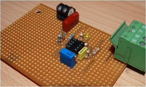
surprisingly what was actually a lot more interesting was putting a simple piece off stainless shunt on the batts ground and putting the multimeter across it ...never thought i would actually find a use for that Mv setting setting on the meter ....it is a lot off fun but all the while the windmill seemed to be looking down saying ...do your worst , if i could care less i would...i guess it knows something i dont.... it usually does niall |
||||
