
|
|
Forum Index : Electronics : Charge controller
| Page 1 of 4 |
|||||
| Author | Message | ||||
readyakira Senior Member Joined: 17/07/2008 Location: United StatesPosts: 114 |
So I was bored the other day and built the charge controller posted in the forums. the Tl084. It did not work as expected. I did substitute a different diode for the 4001 (I think I used a 4004 or 3) and when I was to turn it on both leds would light with 11.7v applied and I could not turn one off but adjusting the trimpots. I went over and over the circuit and could not find the problem. so I am assuming I threw a bad part in. But anyways, I heard there were some changes made to the circuit that may or may not have made the original article? I went thru the pages of post on it and couldnt get clarification from it. can anyone help me with this? I intend to fully rebuild the circuit from scratch and try again incase I put a bad part or two in. but my question is what would it take to make this charge charge at different rates? say once battery reaches capacity it changes to a float charge? It would also be nice if a pulse circuit could be added to allow de-sulphation in one unit. but I think it much better to just be able to float charge. IDK You all may very well explain to me why a float charge is not needed in this type of setup. Don't you think Free/Renewable energy should be mandatory in new buildings? |
||||
| Gizmo Admin Group Joined: 05/06/2004 Location: AustraliaPosts: 5185 |
Hi readyakira I'm pretty sure the web page is up to date, and the circuit does work as others have built it. Are you useing a variable power supply to set up the controller? Glenn The best time to plant a tree was twenty years ago, the second best time is right now. JAQ |
||||
| readyakira Senior Member Joined: 17/07/2008 Location: United StatesPosts: 114 |
I was using a modified PC power supply I Was going to build the basic voltage reg with the lm317s but seeing as I muffed up two attempts at the charge controller board I am losing my confidence. I built the first on vero board and after screwing with it a bit it now don't light up and the voltage reg gets hot almost instantly. so, I built a second on not vero board and was not getting any led lights at all... :( so now I am too frustrated to continue tonight. Not to mention I will probably need to place another order with digikey for more op-amps and voltage regs :( anyways, I'll have to order more tomorrow I guess and try again..... I have more of the non-vero board but it is such a pain to make the jumpers on the back side I'll need to order more of that as well. At least my 60w worth of chineese soalr panels have been doing good. I gave the battery a good charge from the wall to bring the voltage up to where it should be and now the controller that came with the panels frequently switches to a float charge. it would be nice to use that leftover sunlight to power something else not to mention I will someday get my F&P up and running. Don't you think Free/Renewable energy should be mandatory in new buildings? |
||||
| Bub73 Senior Member Joined: 10/12/2009 Location: United StatesPosts: 116 |
You will need a variable power supply to set up the controller properly; Glen just posted some nice circuits for variable power supply's on the projects page. Also some photos will help others to assist you when you have a problem. I have built several of these controllers on different boards and they all work very nicely. Bob |
||||
| Bub73 Senior Member Joined: 10/12/2009 Location: United StatesPosts: 116 |
Here is a copy of my work graphic that I put together while building these controllers and comparing notes with Pete and others; maybe it will help. Glenn check it over I make mistakes and I'm not good at graphics. Bob 
|
||||
| GWatPE Senior Member Joined: 01/09/2006 Location: AustraliaPosts: 2127 |
If the Vreg is overheating, this suggests a short. Have you cut all the tracks under the chip on the veroboard, as is required, but not very clear in pics???? Gordon. become more energy aware |
||||
Downwind Guru Joined: 09/09/2009 Location: AustraliaPosts: 2333 |
Several things here. As has been stated, you can not set this circuit without a varable power supply, and would have guess there may not have been nothing wrong with the build, just the way you tried to adjust it without a variable power supply. Now you have screwed some thing up with the reg over heating. I doubt you have damaged the reg as they have thermal shut down in them. As Gordon said ...look for a short between tracks, its happened before with a solder bridge. If you think the opamp is damaged remove it from the socket and see if the v reg gets hot without the opamp fitted. The page on the site really do need more detail instruction on adjusting the set voltages....Step by step details, as i think this is where many fail to set the circuit up correctly. I wonder if Bub73 has a board handy to be able to put together some detail setup adjustment instructions. 
Sometimes a fresh look on a new day reveals previous over looked mistakes. Dont give up as the circuit works well and has always been a construction error in the past. Its a rather hard circuit to damage badly as there in not much to damage in it. Check your work step by step you will find the problem. Pete. Sometimes it just works |
||||
| Bub73 Senior Member Joined: 10/12/2009 Location: United StatesPosts: 116 |
I don't have a board handy just now; I reordered some yesterday and i'm using my last one trying to layout the AC Desulfator on strip board. Layout software for linux seems to be lacking. I have some photos and adustment instructions somewhere; just changed computers so I'll look. I'll try to sharpen that graphic up a bit also' it seems to have lost a lot of quality when I scaled it down for up load. Bob |
||||
| readyakira Senior Member Joined: 17/07/2008 Location: United StatesPosts: 114 |
I need to find a good place to get more vero board... digi-key sells a ton of boards but not much in the way of vero from what I seen. Most are just perf board.... Radio shack used to sell a bunch but lately their selection really sucks. Edit: Just ordered a dozen vero's from Futurlec.com Will look over the board again tonight.... I did locate the proper diodes and replced the one that I sub'd. Don't you think Free/Renewable energy should be mandatory in new buildings? |
||||
| readyakira Senior Member Joined: 17/07/2008 Location: United StatesPosts: 114 |
ok, so I did find a solder joint that had crossed over to another. I guess way to much solder/desoldering. Anyways back to step one.... here are my voltage readings. with 11.75v applied: Pin 1 11.75 pin 8 6.42 Pin 2 2.57 pin 9 3.96 pin 3 2.75 Pin 10 6.12 pin 4 7.91 pin 11 0.00 pin 5 4.00 pin 12 11.20 pin 6 2.75 pin 13 7.47 pin 7 7.47 pin 14 6.12 until I build the lm317 reg the best I could do high side is 17v which I suppose would not work to well as comparison. Don't you think Free/Renewable energy should be mandatory in new buildings? |
||||
| readyakira Senior Member Joined: 17/07/2008 Location: United StatesPosts: 114 |
, built the reg here is 14.4v readings Pin1 14.4 pin14 6.41 pin2 2.57 Pin13 3.96 pin3 3.40 pin12 6.17 pin4 7.91 pin11 0.00 pin5 2.85 pin10 13.84 pin6 3.40 pin9 1.33 pin7 1.33 pin8 6.16 oops just noticed I labeled the second row pins upside down. They should all read high to low on the second row. I was able to fix it in this post but not my previous one. Don't you think Free/Renewable energy should be mandatory in new buildings? |
||||
| Bub73 Senior Member Joined: 10/12/2009 Location: United StatesPosts: 116 |
Check pins 1,2,3 again pin one looks too high to me, then if you are able to adjust the high and low pots with the supply you have you should be able to tweak it in when you get your variable supply built. I usually do the final adjustments after it is in its enclosure. Bob I tried to sharpen this graphic a bit, hope it uploads better.. 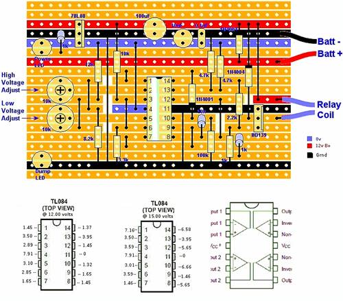
|
||||
| readyakira Senior Member Joined: 17/07/2008 Location: United StatesPosts: 114 |
ok getting closer.... I can now get it to turn off at 12v but I can't get it to turn on when I raise the voltage any unless I take my pos probe from dmm (neg is connected to batt-) and touch it to pin 1 any raise of the voltage seems to do this no matter where I set the high trim pot Don't you think Free/Renewable energy should be mandatory in new buildings? |
||||
| Downwind Guru Joined: 09/09/2009 Location: AustraliaPosts: 2333 |
Yes as Bob said there is something wrong with pin 1 for starters as it should never be able to go above the voltage set by 8 volt reg. I hope you have not mistaken the use of the LM317 and replaced the 8 volt reg with it. The LM317 is used to adjust the voltage supplied to the circuit and not used in the circuit it self. It is posiable you have a solder bridge on a track as power input runs next to a track that goes to pin 1. check your wire connection to the board for the positive battery wire in. And the wire jumper to pin 1. Note to Bob. I no longer have a board for this circuit here and is why i asked if you could do some setup instructions. If you are able to do this i think Glenn will add it to the front page as i feel it is information that is lacking from the build instructions. Concidering how many people build this circuit it would be valuable information. Not all are as understanding as you with this circuit and your input would help many as you have already. Pete. Ps- I like your graphic layout of the pin voltages, it is very clear way of showing what the pin voltages should be close to. Sometimes it just works |
||||
| readyakira Senior Member Joined: 17/07/2008 Location: United StatesPosts: 114 |
nah didnt use the 317 I used the 317 I had to build the vps (which works great I must add.... I must build the other one now so I can get full use of this rather large transformer I have that is a bit bigger then a large grapefruit Don't you think Free/Renewable energy should be mandatory in new buildings? |
||||
| Downwind Guru Joined: 09/09/2009 Location: AustraliaPosts: 2333 |
Now you have sorted some solder faults out what is your pin voltages for 12 volt and 14-15 volts. Try running a screwdriver or knife scratch along between the tracks to wipe off any more slithers as it is not uncommon to get them even to the best of us. Disconnect the power first. By memory you need to set the high pot first so set your input voltage to 14.4 volts then adjust the hi pot till the led comes on. Stop adjustment as it is now latched and will remain latched regardless of further adjustment. Decrease the supply voltage to 12 volt and see if the hi led stays on if so adjust the low pot till the high led goes out. Now you should be set so when you increase the volts to 14.4 again the hi led should light up and remain on till you decrease the voltage back to 12 volt then the led should go out. If so the circuit is working correctly. You can now adjust either pot to give the disired cutin/cutout voltages required Just a note- but i cannot remember which way you need to turn them. The high pot needs to be turned down before starting setup. The low pot needs to be turned up before starting setup. Check pin 2 has a low voltage reading before starting setup (2-3 volts) Check pin 5 has a higher voltage reading before starting setup (6-7 volts) Adjust you pots to give this before trying to adjust setup. Now do the setup as above. Pete. Sometimes it just works |
||||
| Downwind Guru Joined: 09/09/2009 Location: AustraliaPosts: 2333 |
Ready, The other power supply (LM-723)is one i done about 20 years ago and is the best thing i ever built for doing electronics. Mine is setup with amp and volt meters mounted in the panel like a bought power supply and would recommend you do the same. It has current limiting and this allows for things like the leads being shorted out without blowing the power supply up. There is a thread some ways back that would be worth fishing out to read, that i orignally posted it to the forum on. Any questions just ask when you get to do it. Once built it will serve you well for a long time. Pete. Sometimes it just works |
||||
| Bub73 Senior Member Joined: 10/12/2009 Location: United StatesPosts: 116 |
Pete; all I use for final setup is the setup instructions Glenn has on the front page already. To set up the charge controller, you will need a variable power supply and volt meter to measure its output voltage. * Turn the Low trimpot to min (ccw) and the High trimpot to max (cw). * Attach the variable power supply and adjust its voltage to upper charging voltage limit, eg 15v. * Turn high side pot down until the LED lights up and the relay clicks in. * Adjust the power supply to lower limit, eg 12v. * Adjust low trimpot till relay drops out. * Now raise and lower the voltage, checking the relay clicks in and out correctly. * Finished. Maybe I could add them to the graphic, it seems to me many builders of this circuit are missing or not understanding these final steps. I do this at least twice once when the board is complete to make sure everything is working as it should and the final tweak when it is in the enclosure, if it isn't working as it should its has always been something I did or didn't do hence the pin outs on the graphic. I drill a couple holes in the enclosure so that they line up with the trimpots and use a small nonmetallic screw driver to make the final adjustments then plug the holes with a couple short screws. This makes it easy to readjust should there be a need at a later time; like a change in battery type or whatever else comes up. Its late here I'll check back yesterday morning Bob |
||||
| readyakira Senior Member Joined: 17/07/2008 Location: United StatesPosts: 114 |
same here bob, will have to work more on it in the evening tomorrow.... Don't you think Free/Renewable energy should be mandatory in new buildings? |
||||
Bryan1 Guru Joined: 22/02/2006 Location: AustraliaPosts: 2136 |
A real easy way to ensure one doesn't get shorts between the tracks on veroboard is to get a broken hacksaw blade and run the broken edge down the space between the tracks. I do this all the time now as shorts on veroboard gets every frustrating when you first power up and the magic smoke appears. Cheers Bryan |
||||
| Page 1 of 4 |
|||||
| The Back Shed's forum code is written, and hosted, in Australia. | © JAQ Software 2026 |
