
|
|
Forum Index : Electronics : Charge controller
| Author | Message | ||||
readyakira Senior Member Joined: 17/07/2008 Location: United StatesPosts: 114 |
Down, could you help me build that supply? I will put an order into digikey but need to figure out what else would be needed for the supply with lcd display's. The transformer I have is capable of putting out quite a few amps I suppose as it is as big as a normal computer power supply case. But, either way I plan to build it capable of using much larger xformers in the future like maybe a automotive battery charger with 100amp start and 24v. Don't you think Free/Renewable energy should be mandatory in new buildings? |
||||
Downwind Guru Joined: 09/09/2009 Location: AustraliaPosts: 2333 |
Hi Ready, Stick with a 10 amp power supply to start with, and dont go planning a 100 amp system just yet. For the LCD displays i would say have a look on Fleabay (Ebay) at a store called "Sureelectronics" as they have a good range and rather cheap. You will be able to get a volt meter and amp meter to match. Only problem is most lcd volt meters will only go to 20 volt, (you might find higher) in most cases this is more than enough for average bench work. The next problem with lcd is they often need a seperate power supply and can not use the same supply as the voltage they are reading. SO....you might want to concider a couple of analog meters and i think they work well to, but its up to what you want and need to do. You will need a large heat sink to mount the 2N3055 power transistors on, as they generate a fair bit of heat. The transistors i used are T03 package and take a bit of space up. You will need something like 6" x 4" or larger heatsink to mount the 4 transistors on, It can be 4 smaller heatsinks to make up a larger one. The 2N3055 transistors in T03 have the case as collector and will need insolator mounts or the heatsink will be + live. (Can use mica or silicon washers insolators.) There use to be mounting sockets available for T03 packages and these make mounting easy for a small cost but dont know if you can still get them easily. (not needed but handy if you can get them) It will be worth sourcing a decent size box to mount every thing in, so you have a good front area to mount the displays on as well as power switches, voltage and amp control dials, banana plug posts for DC out, indicator lights, etc. you dont want to over clutter a small space if you can help it. I have used an old computer tower cut down before and made a new front panel for it, but much easier to buy a large plastic enclosure if its cheap enough. Take some photos of your transformer and what ever you have that you might use to build this and post to a new thread. I will take some photos of my 20 year old supply and post as well. That way you can run a thread on you build and others might find interesting, rather than lost in this thread. I will form a list of extras required as i think there is a basic parts list in the original "Variable power supply" thread. Its a simple build but a fair bit to do to make it practical. Pete. Sometimes it just works |
||||
| readyakira Senior Member Joined: 17/07/2008 Location: United StatesPosts: 114 |
The xformer I currently have is this one http://www.cardomain.com/ride/2327820/4 Its at the bottom of the page. It is out of a battery backup. The low voltage wires are rather large I would guess 8ga maybe 10ga but more likey 8. I have a friend with an old battery charger that needs switches but I would prob get the thing for a bit of nothing. I use a 50v 25a bridge rectifier with a CPU heatsink w/fan to keep it cool. The brdige will still get hot under load. I used this for a while when I was playing with HHO like in the pics above on that page. the last fuel cell I still have but it sits dormant on a shelf. Don't you think Free/Renewable energy should be mandatory in new buildings? |
||||
| GWatPE Senior Member Joined: 01/09/2006 Location: AustraliaPosts: 2127 |
If you are talking about HHO, then the device you mention would be an electrolysis unit. Fuel cell I believe relates to a bi-directional device that can convert water to elemental hydrogen & oxygen with electricity and reversibly convert elemental hydrogen and oxygen to water, with the production of electricity. Gordon. become more energy aware |
||||
| readyakira Senior Member Joined: 17/07/2008 Location: United StatesPosts: 114 |
Yes but I beleive it all depends on how you look at it. Both of our terms would be correct. The "cell in my case was actually a series of cells, like a battery that emit a fuel (hho) thus a fuel cell. But as you state it is more commonly used in terms of the hydrogen cars in how it emits electrons. Fuel cells are also used in racing and are merely a container that holds fuel, usually suspeneded for safety. but either way I was more interested in the transformer. Upon looking more inspection the low voltage wires are 10awg so in theory it should be capable of? I now in 220v situations it will carry 30amps. is that so in dc low voltage? or does it maybe have more to do with the watts? My semi-educated guess would tell me it should be able to handle 30amps. I will have to get some measurements on vac out on the diff wire combos. I think yellow to white is about 26-27v but I will measure and post shortly. Don't you think Free/Renewable energy should be mandatory in new buildings? |
||||
| readyakira Senior Member Joined: 17/07/2008 Location: United StatesPosts: 114 |
so, yellow to white gives 17.3vac either purple to either yellow or white gives 8.65v I am in states so these are done with 110vac in. when I rectify it with a bridge rectifier I get 15.95vdc from white to yellow but, when hooked to the vreg I get 22.03vdc out? How does the reg increase voltage? Don't you think Free/Renewable energy should be mandatory in new buildings? |
||||
| Downwind Guru Joined: 09/09/2009 Location: AustraliaPosts: 2333 |
Hi, Just had a look at the photos and i thought you posted a photo of your bong in the first photo  i was wrong and its a hho cell. i was wrong and its a hho cell.
The trany looks like at least 10 amp and should do fine. After your bridge and before the v reg you will need so large capacitors, somewhere from 1000-10,000 uF to smooth the ripple out. If you add the caps you will find the voltage will come up to around the 22 volts you reported. Its not the vreg increasing the voltage its the caps smoothing the ripple and the meter reading correctly. If you could look at the wave on a cro then you would soon see the peeks and troughs after the rectifier without the caps, and with the caps they charge on the peeks and dump on the troughs giving a steady flat dc output. As the trany is going to give about 20 volts than a lcd display would be ok as you wont get much above 20 volts anyway. Pete. Sometimes it just works |
||||
| readyakira Senior Member Joined: 17/07/2008 Location: United StatesPosts: 114 |
Got the Controller working thx guyz!!!! Musta been a few trace problems. Now I need to order the parts to build that better supply. Sooner I get that done sooner I can play with the other ups I have!!! Don't you think Free/Renewable energy should be mandatory in new buildings? |
||||
| readyakira Senior Member Joined: 17/07/2008 Location: United StatesPosts: 114 |
kewl Think I have a good source for some seious HS. I have an old kenwood stereo amplifier that burned up and rather then getting it fixed I'll use the parts. It has several large amps in it, and they are mounted to a HS across the whole length of the enclosure. Don't you think Free/Renewable energy should be mandatory in new buildings? |
||||
| Downwind Guru Joined: 09/09/2009 Location: AustraliaPosts: 2333 |
Can you use the old stero enclosure and add a new face to it. Good to hear the controller is working. As i said its always a construction fault why these dont work, but most dont want to believe its a problem with their work. At least you stuck to it and worked it out. Pete. Sometimes it just works |
||||
| Downwind Guru Joined: 09/09/2009 Location: AustraliaPosts: 2333 |
One thing that would be worth asking when you order the parts, is to ask if the 2N3055 transistors can all be supplied with the same batch numbers. The reason is all transistors are not exactly identical and ones of the same batch will be much closer to each other than from odd batches. It wont matter greatly, but if you have the option than take it. (if you dont ask you dont get) The old stereo might even have 2N3055's in it as it was common in past years. If so there will be likely a batch of 2n2955's as well, which is the PnP version of the NpN 2n3055. Have a close look at what you have. Pete. Sometimes it just works |
||||
| Gizmo Admin Group Joined: 05/06/2004 Location: AustraliaPosts: 5036 |
Yeah good to hear you got the controller working. 
Sometimes its better when a project doesn't work first time, you'll learn more trying to work out whats wrong with it. I do need to improve those set up instructions though. Glenn The best time to plant a tree was twenty years ago, the second best time is right now. JAQ |
||||
| Downwind Guru Joined: 09/09/2009 Location: AustraliaPosts: 2333 |
Hi Ready, You asked about why the voltage was different after you rectified it and then it changed when you added the v reg. I took some photos of the voltages on the CRO for you to see and help to understand what is going on. Firstly your meter will not read peak to peak of the wave and will give an average of the voltage. For the photos i used a 12 volt rated transformer and as you will see the peak to peak voltages are much higher than this. Each graduation from bottom to top of screen is 5 volts. This is the straight 12 volt AC out of the transformer. 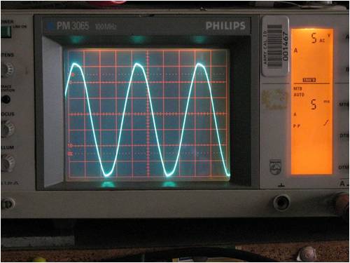
As you can see from the bottom of the wave to the top it is 35 volts peak to peak. This is with a bridge full wave rectifier added. 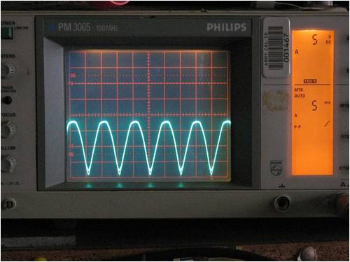
Here you can see it is rectified but not a smooth DC output, and is about 17 volts peak to peak. Remenber you meter can not read to the peaks, so you see and average of this. Final photo is with a 3300 uF capacitor added for filtering. 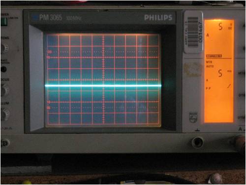
Now we have a nice smooth ripple free DC output of about 17 volts. Your meter would now read 17 volts. It should be noted that there was no load on the circuit when the photos was taken and a load would drop the peak voltages back some. I had done this some years back to proove to a so called expert in garden lighting why Led lights kept blowing up after a short time in use. His answer was leds are crap and was not worth using, so he advised people to use the 20 and 50 watt halogen lights. (experts for you??) The problem is Leds draw so little power the peak voltages they were subjected to was way over their 12 volt AC rating (more to 35 volt) and would burn them out. The use of 400 watt transformers did not help either. The simple practice of adding a rectifier would drop them back to 17 volt peak which they could handle and gave a long life of use. I have seen the use of down light transformers do the same and give reduced led life. But who am i to comment as im not an expert like some claim to be. I hope this answers your earlier question some what. Pete. Sometimes it just works |
||||
| Downwind Guru Joined: 09/09/2009 Location: AustraliaPosts: 2333 |
I posted some photos of the original variable power supply i built in the "Variable bench power supply circuit" thread. Looking back it was not pretty work but has served me well for many years. Pete. Sometimes it just works |
||||
| MickWh Newbie Joined: 08/05/2010 Location: Posts: 19 |
Hi guys, I am having troubles with the controller circuit, or more specifically maybe, the relay. I have only just read this lot, so will be checking pin voltages Monday. The current "problem" is that the relays are not clicking in or out nice and quick, they tend to click in and out repeatedly over a range of say 12 to 12.1 volts. This would seem to be detrimental to the longevity of the relay. Also same behavior at higher voltage range, eg 15V. Also out of interest just wondering about the behavior of disconnecting the turbine at less than 12V battery voltage. This would seem to be that if the battery has a load on it and drops the voltage under 12v it will disconnect the turbine from charging during a time when the battery needs it most. I am currently having troubles with the circuit activating the relay at only one adjusted voltage, not 2. Sorry to have so much generality in the issues, will try and be more specific as I know what I am looking for. |
||||
| Downwind Guru Joined: 09/09/2009 Location: AustraliaPosts: 2333 |
Your problem is simple. You have the low voltage set to low By increasing the low voltage to 13 or 13.2 volts when the circuit trips to dump it will stay latched till the battery voltage falls below the low setting, then there will be some time the battery will take charge for again before the relay latches again to dump. This should stop the toggling of the relay you have at present. Pete. Sometimes it just works |
||||
| Shelly Newbie Joined: 22/12/2009 Location: SpainPosts: 25 |
I have just finished putting together the controller, it doesn't work  . As an electronics newbie I don't know quite what has gone wrong. What is happening is that the relay clicks in at the set voltage but when I reduce the voltage to set the low volts the relay immediately clicks out. I made mistakes in the construction. The v reg overheated because of shorts, that has been replaced. The biggest mistake I made was to forget to put breaks in the vero board between the op-amp pins. Could this have been damaged? Here are the voltages at the pins. They do not follow those on the diagram. . As an electronics newbie I don't know quite what has gone wrong. What is happening is that the relay clicks in at the set voltage but when I reduce the voltage to set the low volts the relay immediately clicks out. I made mistakes in the construction. The v reg overheated because of shorts, that has been replaced. The biggest mistake I made was to forget to put breaks in the vero board between the op-amp pins. Could this have been damaged? Here are the voltages at the pins. They do not follow those on the diagram.
12volt Pin 1 7.07 Pin 14 1.24 2 2.55 13 3.96 3 3.56 12 1.44 4 7.95 11 0 5 4.16 10 6.53 6 2.82 9 7.55 7 7.36 8 1.48 15volt Pin 1 7.07 Pin 14 1.25 2 2.54 13 3.96 3 3.56 12 1.47 4 7.95 11 0 5 4.16 10 6.53 6 6.56 9 7.35 7 7.35 8 1.48 Any help and suggestions would be greatly appreciated. Thanks |
||||
| Bub73 Senior Member Joined: 10/12/2009 Location: United StatesPosts: 116 |
Could you post some photos of your board ? Also make sure all the traces are cleanly cut the ones for pins 8,9,10 look suspect buy your voltages. Bob |
||||
| Shelly Newbie Joined: 22/12/2009 Location: SpainPosts: 25 |
Hi Bob, I'll post a couple of photos tomorrow. I don't have a photo manipulation program on this computer. I've cleaned yet again the traces and checked that the resistors are correct. The voltages at pins 8 and 14 are dependant on the position of the low volts pot. I presume this is correct? The relay still clicks out when I reduce the voltage to adjust the low volt pot. I or someone will get it sorted out one day!  |
||||
| Bub73 Senior Member Joined: 10/12/2009 Location: United StatesPosts: 116 |
Hi Shelly. Turn the Low trimpot to min (full counter clockwise)it should stay latched when you lower the the input voltage on your supply to where you want it, then turn the Low trimpot clockwise till the relay drops out. Bob |
||||
