
|
|
Forum Index : Electronics : Warpspeed’s MOSFET mounting method
| Page 1 of 11 |
|||||
| Author | Message | ||||
| azhaque Senior Member Joined: 21/02/2017 Location: PakistanPosts: 131 |
Having seen and repaired a number of inverters with blown MOSFETs I had been on the lookout for an alternate method of mounting the MOSFETs. However I think the two parallel rows with capacitors in-between is now a de-facto world standard being followed in making of the MOSFET Boards. In the thread 'Building an inverter from scratch' Warpspeed has spoken about such an alternate method. There is also a photograph (albeit a shot from afar) of MOSFETs mounted horizontally using connectors. Warpspeed describes the unit in that thread briefly. He writes about the MOSFET legs being clamped/screwed down rather than being soldered. There are obvious advantages of this system, the most important being the doing away of de-soldering and re-soldering for diagnosis and replacement of blown MOSFETs. I would like to discuss this method in further detail since I am starting to build an inverter (3 kw) and if feasible use this method instead of the standard one. Warpspeed's experience and comments to the above end would be very helpful. Also a close up of 'the beast' should set the ball rolling in this thread quite nicely- Thank you. azhaque |
||||
| Warpspeed Guru Joined: 09/08/2007 Location: AustraliaPosts: 4406 |
If you use the larger TO-247 packages (instead of TO-220) the legs are 5mm apart which corresponds to the readily available 5mm pitch screw terminal blocks. Unfortunately my cheap crappy camera has blown up for good, and I plan to buy something better with a macro lens that will take decent close up pictures. But I cannot afford to do that right now, so no photographs unfortunately. Anyhow these are the terminal blocks, and you can get them in either side entry for mounting your mosfets horizontally onto a flat heatsink. Or the top entry blocks will allow the vertical mounting of your mosfets. 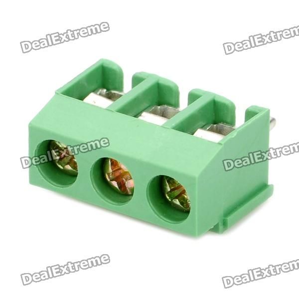 It saves a HUGE amount of work if you have a blow up, and you can remove test and replace mosfets many times without the circuit board killing unsoldering and resoldering process. Here is an old picture of a project using flat mounted mosfets. 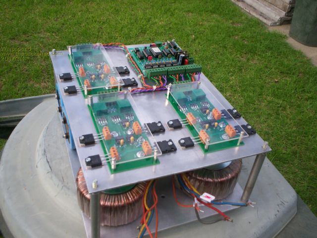 If I had to, I could replace all twelve of those devices in just a very few minutes. Cheers, ĀTony. |
||||
| azhaque Senior Member Joined: 21/02/2017 Location: PakistanPosts: 131 |
Thanks Tony. The many advantages are obvious. I can't fathom the reason why this mounting method is not used more frequently when blown MOSFETs in power electronics is a reality of life. Maybe it is the infatuation to make units smaller and more compacts which prevents this. Anyway some supplementary questions. The picture shows that the connector that you recommend has these pins sticking out at the bottom which are normally soldered onto the bottom copper. In your inverter I see that these connectors are soldered onto the top copper. Can you please expand on that. Secondly I don't see the big capacitors, near the MOSFETs. And how does the (+) and (-) buses get into the Boards? Is it thru the 3 screws that we see on each of the Boards? I hope these are not too many questions for one post. Guess this is the cost of being a Guru  azhaque |
||||
| Warpspeed Guru Joined: 09/08/2007 Location: AustraliaPosts: 4406 |
My circuit board has tracks both sides with plated through holes. The terminal blocks just solder into the holes in the normal way, and connect to the tracks on both sides. The power connections to each board are through the four 4mm nuts and bolts that you see, with bolted lugs underneath, connecting to +dc, -dc, ground, and output. The large aluminium plate is completely cut away underneath the circuit boards,(except near the corners) so all the high power connections to the boards are made from underneath. This is not the usual high frequency PWM type of sinewave inverter, but three individual low frequency square wave inverters with the outputs combined through transformers to produce a multi stepped output waveform. The output has 27 steps and looks like this compared to a true sinewave: 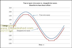 It looks totally different because it is totally different. The large capacitors for the positive and negative high voltage supply are just peeking out from underneath the top aluminium plate at the back. This was all in the final stages of completion when I took the picture about a year ago. Its running right now and supplying all my power during the day, and has been for a long time with total reliability. Cheers, ĀTony. |
||||
mackoffgrid Guru Joined: 13/03/2017 Location: AustraliaPosts: 460 |
Warpspeed I've seen a couple of your posts (on the various OzInverter posts) regarding the Trace style inverter and a brief description on your high voltage dc converter and inverter. This style of inverter sounds perfect for a workshop inverter (hence my interest) and especially like the low frequency aspect. I'm trying to imagine how the Trace style inverter works in more detail. Is it simply three or more transformer secondaries in series? And what do they call this mode of inverting? Many thanks for your considerable contributions Andrew |
||||
| Warpspeed Guru Joined: 09/08/2007 Location: AustraliaPosts: 4406 |
I have no idea what it is called, or if it ever had a specific name. The idea is not new, it has been around since the very first push pull bipolar transistor inverters, probably since the 1960's. Long before PWM or microprocessors came on the scene. The fundamental idea is to add voltages in the secondary windings of several square wave inverters. Everyone is familiar with digital to analog converters, and how complex waveforms can be generated by a d/a converter by adding voltages in a 1, 2, 4, 8 binary sequence. Now a square wave inverter has three possible states not two. Positive, zero, and negative. That is easy to see. We can generate three discrete voltage levels with one inverter. Let's assume +300v, zero, and -300v. That could be a low voltage push pull inverter driving a transformer with 300v secondary, or a half bridge switch fed directly from +/- 300v dc rails. If we get our duty cycle about right, the harmonic distortion is about 40%. Three switches A, B, and C, three voltage levels. We definitely need the third switch (C) because we cannot just open circuit the output with inductive loads. The lagging out of phase current must have a continuous path through the inverter with the output voltage at zero volts. Even with zero volts, there can be many amps still flowing through an inductive load. So this is a simple functional diagram of our first #1 "Big" inverter : 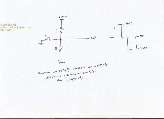 Now we build a second inverter, but this time with a voltage of only one third by using a 3:1 transformer to give us +100v, zero, or -100v. Functional diagram with #2 "medium" inverter added. This now gives us three different but lower voltages with three more switches. Combined we get nine (3x3) possible output voltages : 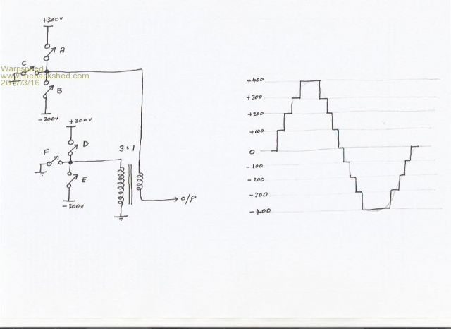 If you are building a 1.3Kw inverter, the transformer only need to carry 333 watts. And the switching is still low frequency, and you can get away very nicely without any output filtering. Also notice the peak voltage goes higher than the dc rails by one third. So we add a third "small" inverter to that with another transformer that has one ninth the voltage. And we get (3x3x3) voltage steps. Thirteen up, zero and thirteen down with even lower harmonic distortion, about 4%. That is probably good enough for most people. The transformer only needs to be one ninth the power rating about 144 watts so its small. A fourth "tiny" inverter with a 48 watt transformer gives (3x3x3x3) 81 steps, forty up and forty down and easily less than 2% distortion unfiltered output. Its simple to build with off the shelf transformers. No high frequency PWM means it will work first time without blow ups GUARANTEED. All the four inverters can use identical circuit boards I am using high voltage rails +/- 235v dc gives me 240v rms output. But if you use a "Big" transformer with push pull or full bridge drive, a low voltage battery inverter is entirely practical. Voltage regulation over a wide input range is also possible, which I have already done, but I will leave that for another post if anyone is interested. The switching patterns are all stored in EPROM, and the addresses are just clocked through in sequence from a counter. The steps are all the same height, but the switching times are non linear which is where the3 sine wave shape comes from. Cheers, ĀTony. |
||||
| mackoffgrid Guru Joined: 13/03/2017 Location: AustraliaPosts: 460 |
Thanks Tony So simple. To be clear, to achieve the 200v, you switch in the 300v and the -100v ? (which screws with my head a little  ) )To drive this from, say a 48v system, you would scale down your design to 48v and then simply use a standard big 48v to 240 v transformer ? or is it better to smps the 48v to 235v ? Very interested Andrew |
||||
| Warpspeed Guru Joined: 09/08/2007 Location: AustraliaPosts: 4406 |
Yes, exactly. Two inverter big/small waveform with 100v steps is still pretty rough, but its easy to explain. small big 0v = 0v + 0v +100v = +100v + 0v +200v = -100v +300v +300v = +0v +300v +400v = +100v +300v So there is a sequence that repeats up and then down for each half cycle. The measured distortion off the grid here is about 4% which is about the same as having a 27 step three inverter set up which I am running right now. Four inverters will give less than 2% distortion with 81 voltage steps. It looks like a lovely sine wave shape, with just a bit of high frequency ripple on it. Filtering that out would be very easy to do. It should be realised that although the voltage waveform has the steps in it, the current through an inductive load will be a dead smooth sine wave even with very few steps. So its a very motor and transformer friendly waveform. Cheers, ĀTony. |
||||
| mackoffgrid Guru Joined: 13/03/2017 Location: AustraliaPosts: 460 |
Thanks Tony Just to be clear I've attached 2 drawings if you wouldn't mind perusing them Are both correct? Which would be the most appropriate (Assuming at least one of them is correct) For a test design: (and replacing a sorry Power Jack) -I have a LiPO Battery that rarely goes under 26v (28v max) - Going for 3kW to handle HWS and pumps Thanks Andrew 2017-03-16_064137_cascadeInverter_2.pdf 2017-03-16_064055_cascadeInverter_1.pdf |
||||
| Warpspeed Guru Joined: 09/08/2007 Location: AustraliaPosts: 4406 |
Two possible ways to do this, use a dc/dc converter to generate voltage regulated positive and negative high voltage supplies. Or do it straight from a 48v battery by making all of the transformers step up transformers and just switching 48v straight into the primary of each transformer. It depends how many steps you want. Suppose you decide to use three inverters which will give (3x3x3) 27 steps. And you want to end up with 240 volts rms. The highest step must produce the maximum peak voltage of 1.414 x 240v = 340 volts. And our inverter secondaries when added together in the same phase must equal 340 volts. So the big inverter has X volts The 1/3 middle inverter .333X volts And 1/9 the small inverter .111X volts All three will be 1.444 X which we know must add up to 340 volts peak. So the big inverter secondary would be 340/1.444 = 235 volts The middle inverter a third of that 78.5 volts And the small inverter one ninth 26 volts If we add those together we get 235 + 78.5 + 26 = 339.5v which is pretty close to our desired 340 peak voltage. Those are the required secondary voltages. Or you can wind some 48v primary transformers to do it direct from a battery. Or you could generate +/- regulated 235v dc rails some other way, direct from solar panels for instance, and not require the largest transformer. If you are doing it straight from a battery, you would wind your three transformers for the lowest expected battery voltage, maybe 40 volts for a 48 volt system. Then have multiple lookup tables in EPROM. The lowest battery voltage will have the full 27 steps in this example. As battery voltage rises you can switch to another lookup table in EPROM that makes all the steps very slightly narrower, so you still get 240v at say 41 battery volts. If you keep going in one volt steps, all the steps get narrower as the input voltage rises, and the very top step may disappear entirely. So you might have twenty lookup tables from 40v battery input to 60v battery input, or whatever you decide you need. A larger EPROM just uses the high order address bits to switch lookup tables on the fly, to regulate the 240v output. An up down counter can do that in hardware, or the whole thing could be done with a microcontroller with a large enough internal EPROM. I did this many years ago with a 68HC05C8 that had 16K eprom and it worked great. Today the HC05 is a dinosaur, much better micros around today. Or you can just glue some CMOS counters and a big EPROM together with some hardware and zero software, and do it that way. Its easier with regulated input voltage because you only need one lookup table. Cheers, ĀTony. |
||||
| Warpspeed Guru Joined: 09/08/2007 Location: AustraliaPosts: 4406 |
Second circuit is correct. But you also need to short out each transformer when it is in the zero volts condition with a voltage clamp. If you plan to use bridges for primary switching, a third winding on each transformer is probably the easiest way to do that. If you make it a fairly high voltage winding, the current will be lower, smaller mosfets will work, and it will provide a more efficient short across the secondary during the zero volt output condition. 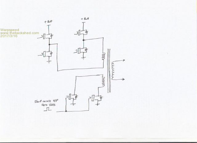 Cheers, ĀTony. |
||||
| mackoffgrid Guru Joined: 13/03/2017 Location: AustraliaPosts: 460 |
Thanks I like the regulation idea. I guess when you zero the voltage on the winding, that the turns current ratio needs to equal the current through the secondary winding? I can see that the transformer and switching costs are higher in this design, perhaps more complexity of transformers and switching, payoff being a lower tech approach regarding FET switching (lower Gate drive issues); after all the heavy current cycle will be turn off milliseconds before zero cross over. Whilst I'm inclined towards the eprom method for reliability, prototyping would certainly be easier with a microcontroller. Very interesting, Thanks for your assistance, Andrew |
||||
| Warpspeed Guru Joined: 09/08/2007 Location: AustraliaPosts: 4406 |
Your example is roughly 4.4Kw, so secondary current of all the transformers will be nominally 18.3 amps. So all of the secondary windings, and whatever clamps the secondary current needs to be designed on that basis. That, plus the secondary voltage determines the Va rating of each transformer. Yes, there are a lot of parts and the transformers are large and expensive, which is why this method is only usually used at very high power levels. At lower powers PWM is a lot more practical, and a lot more cost effective. But there is a practical limit to how far high frequency PWM can be scaled upwards. If I was building a 100Kw low distortion sine wave inverter, I would not even consider high frequency PWM as being a viable option. If you want something absolutely bullet proof, easy to get going, and completely trouble free, this is definitely the way to go. As many here (myself included) have learned the hard way, high power high frequency PWM can cause a lot of tears and frustration when it keeps blowing up. Cheers, ĀTony. |
||||
| mackoffgrid Guru Joined: 13/03/2017 Location: AustraliaPosts: 460 |
I'm a year or two away from house building again. At which time I'll be going nom. 48v system and much larger inverters - I want to be able start a car hoist, or compressor etc. (tempted to go higher in battery voltage but feel a bit insecure as in not being able to get off the shelf inverters , chargers in case i fail) Currently have a nom 24v system, 3kw Latronic (working well) for the house and 8kw (haha) PowerJack that works for a while. I use it for pumping and HWS. Do you see any evidence of the distortion in TV sets, stereo or other appliances with your current setup? I've attached an updated schematic if you don't mind checking the scheme of it. (I've shown back to back Nfets to short the windings - done this before but maybe not at this current) How efficient are these compared to PWM models? I don't expect much difference but I don't fully understand the affects of short those windings. I'm guessing this would cost 20% to 25% more to build ~ But at the end of the day, still cheap compared to brand name inverters. |
||||
| mackoffgrid Guru Joined: 13/03/2017 Location: AustraliaPosts: 460 |
2017-03-16_101348_cascadeInverter_11.pdf |
||||
| Warpspeed Guru Joined: 09/08/2007 Location: AustraliaPosts: 4406 |
The clamping mosfets should have the sources tied together, and the open drain connections to do the clamping. There are several options with the clamping. If you use a separate floating winding the sources of the clamping mosfets can both be grounded, which makes driving both gates through a two input NOR gate extremely simple. When both sides of the bridge are off, the clamp comes on. You only need two data bits out of the EPROM, the clamp is driven via a NOR gate from those two data outputs. All with sufficient dead time provided of course. This clamp could also be placed right between both sides of the bridge, or even directly across the secondary winding. Current will be much higher there though. But then the gate drive to the clamp needs to be fully isolated and independently powered. It all works, but how best to do it is up to you. If you are winding your own transformers, its no big deal to add a third winding with plenty of turns to keep the current in the clamp low. Providing isolated gate drive to a fully floating clamp not difficult, its only a few extra parts on the circuit board and no big deal. I do not watch TV, but I have not had any problems with the slight ripple on the voltage waveform. It would not be difficult to filter, but I have not bothered to do so with no ill effects. As for efficiency, there are several different aspects to that. Arguably the most important for a home inverter is zero load idling power. The biggest villan will be the magnetising current of the "Big" transformer. That is going to be a problem with both this method, or with PWM. The great enormous thing is sitting right across 240v and humming quietly to itself and drawing some continuous no load power. Only probably 10 to 30 watts, but its always there 24 hours per day. If you use high voltage +/-235v dc rails to power this (as I am myself) there will be no "Big" transformer required. So it becomes much more efficient at night when loads are low. If you are building a high power direct off battery inverter either PWM or stepped sine wave and using a very large toroidal transformer, there is really no way around that particular problem. Now the medium and small transformers apart from being much smaller, also run at a faster switching frequency, and the zero load magnetising current will be much less than if they were running directly at 50Hz, so the power loss there is negligible. Its just the big 50Hz toroid that is the problem. I did some testing on toroidal transformers, and as you increase the frequency above 50Hz, the magnetising current slowly reduces as frequency rises up to about 350HZ. Above that the no load current rises very sharply. So for other than the very large 50Hz toroidal transformer, the smaller transformers are operating in their most efficient region for absolutely minimal no load power loss. At full load flat out power, conduction losses predominate, mainly the copper in the transformer and voltage drop across the mosfets. That will be pretty equal for either PWM or stepped sinewave inverters. No advantage or disadvantage either way. High frequency switching losses should in theory make PWM inferior, but the actual losses involved are so very small anyway, that can be ignored. The main advantage of stepped sinewave is how well it handles very difficult reactive loads such as starting up multiple flourescent lights simultaneously, or starting large motors in refrigerators or air conditioners. The zero volt clamps have a lot to do with how well out of phase reactive currents are handled. PWM can be more fragile unless its very carefully designed and protected, as there is really no obvious path for out of phase currents to flow back through a PWM inverter. If you read the fine print instructions for one of those 8,000 watt Power Jack inverters they will tell you how many flourescents or motors you can run without blowing it up. And its nothing like 8Kw !!! My own inverter prototype used transformers I already had, with 7 amp rated secondaries. In theory only 1.68Kw max power. I am using 50 Amp rated IGBTs for switching and clamping, and no current limit circuit (Its only a rough initial prototype) Anyhow one day I was using my 300mm Makita steel cutting saw, and did not realise I was running off my inverter. (I have both direct grid and inverter outlets in my workshop). I was cutting up some really heavy steel I beam sections, and really leaning down on the saw, and the 20 Amp circuit breaker popped. So I reset that and went on cutting not thinking too much about it. A couple of minutes late the inverter blew two IGBTs and a driver chip. Not too bad really, actually I was pretty impressed how tough that inverter is. Replaced the IGBTs and plugged in another driver chip which took about five minutes, and that inverter has not missed a beat since. The final version which is almost finished will have four inverters (81 steps) and 2.8Kw rating. I could have fitted even larger transformers for 4Kw, all are off the shelf items, but simply do not need 4Kw. The little prototype has vastly exceeded even my most optimistic hopes. How many Kw does it take to pop a 20A C curve thermal circuit breaker ? A lot more than 5Kw and it took it for at least a couple of minutes the first time before the 20A breaker tripped. Not bad for a 1.7Kw rated inverter. Cheers, ĀTony. |
||||
Grogster Admin Group Joined: 31/12/2012 Location: New ZealandPosts: 9985 |
This stepped-sine-wave idea is exceedingly interesting. Somnething you said in the previous page of posts was: [Quote=Warpspeed]Its simple to build with off the shelf transformers. No high frequency PWM means it will work first time without blow ups GUARANTEED.[/Quote] Why? What is the difference in the PWM driven concept over the stepped-sine-wave concept, that would GUARANTEE you don't cook MOSFETS? The stepped-sine sounds like the best design, actually for that reason and the fact you mention you use off-the-shelf transformers. Further to that, exactly what off-the-shelf transformers are you referring to? IE: Where did you get yours, and what were their ratings etc. Smoke makes things work. When the smoke gets out, it stops! |
||||
| Warpspeed Guru Joined: 09/08/2007 Location: AustraliaPosts: 4406 |
O/k, the problem with high frequency PWM is mainly the very high switching frequency required, and all the problems with that including stray inductances, grounding, layout, and getting multiple mosfets to not only current share, but switch simultaneously in a controlled way. It looks easy getting ten mosfets to switch 200 amps. But what if just one mosfet turns on slightly ahead the other nine, or is the very last one to turn off carrying all of the current before it can do so ? When you drive a high voltage transformer with a large step up ratio, there will be a lot of stray capacitance associated with the high voltage secondary. This capacitance has to charge and discharge every PWM cycle at high frequency. There is nothing much to limit peak currents during actual switching. Also, its not uncommon with an inductive load to have a high current flowing through the mosfets that are off, in the reverse direction through the internal source drain diodes. These inverse diodes are sometimes have fairly slow recovery times. When the opposite pair of mosfets turn on, there can be a very high reverse recovery current spike which can cause us some real problems. Its not as easy as it looks. All the same problems exist switching at 50Hz that occur at 20Khz, but the less frequent occurrence means the effects are less dramatic and potentially a lot less destructive. Now about transformers............ I am using +/- 235 volt dc rails coming strait out of my MPPT solar controller during the day, and at night from a grid powered transformer rectifier. No battery as yet. This does not require a transformer for the #1 large inverter. Taking the #3 small inverter first, ideally it requires a 9:1 ratio, and the secondary current should be the same as the inverter output current rating. I am using a transformer from Altronics part number M5525. It has a 230 volt primary and a 25 volt secondary rated at 12 amps (300Va) The ratio works out to 230/25 = 9.2 That is at full load. At less load, the output voltage will be very slightly more, and the ratio very slightly less. In any case, it the best transformer I could find to get as close to the optimum 9:1 ratio. Now the #2 medium transformer needs to be exactly three times the voltage and three times the power at the same rated secondary current. Haha, dead easy just use three more of the M5525 transformers. All three primaries in parallel, the three secondaries in series giving 75 volts at 12 amps. Its also a lot easier to package three 300Va toroids than one 900Va toroid even if I could get one with 75v 12amp secondary. The #4 transformer needs to be 27:1 still at 12 Amps. I used a M5309 which is rated 9v at 17.8 amps. It should really be 8.5 volts, but by wrapping one turn back around the core the wrong way I lowered the voltage slightly. Anyhow with four 300Va transformers and one 160Va transformer I get a 12 Amp inverter 2,880 watts continuous rating, and a lot more than that for short bursts. Altronics also have 500 Va transformers that have the same voltages. M5725 is 25v at 20A which would be ideal for a 4.8Kw inverter. If you are going to make something to run off a low voltage battery you will probably need to wind something yourself. But the voltages are all low, both primary and secondary, except for the #1 big transformer. With luck you can probably recycle a large toroid from a grid tie inverter that already has a 230 volt winding on it. The transformer issue requires a bit of thought, but its not a difficult problem to overcome. I was very fortunate that I could use unmodified off the shelf transformers, more luck than anything else. Cheers, ĀTony. |
||||
Madness Guru Joined: 08/10/2011 Location: AustraliaPosts: 2498 |
Hi Warp, Is there any reason preventing you from putting all the windings on one large Toroid and have multiple primaries? There are only 10 types of people in the world: those who understand binary, and those who don't. |
||||
| Warpspeed Guru Joined: 09/08/2007 Location: AustraliaPosts: 4406 |
It could work, and has been done but only for a very limited number of steps. You would have to switch directly between voltage tappings on the primary. The problem with that is you need a set of mosfets to drive every individual tap. Not too bad if you only want a very few steps. With tappings, every tap has to carry full rated power. For 27 steps you would need 13 taps and thirteen mosfet bridges. But by using three inverters with three bridges we triple the number of available steps for each additional inverter. Not only that, each successively smaller inverter shrinks to one third the size and power rating. My prototype used three inverters and I only used six data bits in my Eprom. I though what the hell, build a fourth inverter, its only about 100 watts and use all eight data bits and get 81 steps instead of 27. To do that with tappings would require 40 taps ! Cheers, ĀTony. |
||||
| Page 1 of 11 |
|||||
| The Back Shed's forum code is written, and hosted, in Australia. | © JAQ Software 2026 |
