Notice. New forum software under development. It's going to miss a few functions and look a bit ugly for a while, but I'm working on it full time now as the old forum was too unstable. Couple days, all good. If you notice any issues, please contact me.
mackoffgrid Guru Joined: 13/03/2017 Location: AustraliaPosts: 460
Posted: 05:09pm 16 Mar 2017
Copy link to clipboard
Print this post
Many Thanks Tony
Quite right re: the Clamping Fets (too quick wacking the drawing together)
I like the robustness of this design - so I'll give it a go. I'll make a 3-4ish kW replacement for the PJ . But later, if all goes well, I'll look at making a 48v workshop inverter somewhere between 6kW to 10kW.
I still may do an Ozinverter some time later.
I have some GTI's to scavenge the cores out of, like a 3kW aerosharp and some 1kW GTI cores to make the next smaller transformer. I could buy smaller cores for the rest. So adding some clamping windings should be ok. The idea of clamping the bridge is also interesting.
If somebody knows where to buy transformer Wire from in Brisbane ?
Cheers
Andrew
Madness Guru Joined: 08/10/2011 Location: AustraliaPosts: 2498
Posted: 05:17pm 16 Mar 2017
Copy link to clipboard
Print this post
Any motor rewinding shop has the wire. More old school ones are probably your best bet. I know one place here on the Sunshine Coast that will let me take a spool and charge me for the weight difference when I take it back.There are only 10 types of people in the world: those who understand binary, and those who don't.
Warpspeed Guru Joined: 09/08/2007 Location: AustraliaPosts: 4406
Posted: 05:27pm 16 Mar 2017
Copy link to clipboard
Print this post
Andrew, you can start with just the clock and EPROM and gate drivers, that will keep you out of mischief for quite some time. All that is identical for any final power rating anyway.
One thing you need to watch is that EPROMS put out a burst of crap on the data lines every time the address changes. Using a synchronous counter for the address is not a solution, the problem is the address decoding within the EPROM. So might as well use a crappy ripple counter for the address counter, and latch the data output on the output once it is stable.
If you use a microcontroller with internal PROM there should be no problems.
Another tip. If you make address 0000 the zero crossing point at the beginning of the sine wave, activating reset on the counter will instantly turn everything off and activate the voltage clamps. Ideal for a very fast over current shut down.
I have not fitted current limit yet, but my counter reset pin does come out to an opto isolator which I plan to eventually use for fast inverter shutdown.
I can give you some EPROM data but only for fixed full output voltage. For a battery you will need a series of lookup tables that you will need to derive yourself depending on your own requirements. But I can give you one to get started with if that will help.Cheers, �Tony.
mackoffgrid Guru Joined: 13/03/2017 Location: AustraliaPosts: 460
Posted: 06:20pm 16 Mar 2017
Copy link to clipboard
Print this post
I haven't played with eproms for 20 to 25 years - havent had to think much about the logic involved but its coming back to me :-)
Probably have to use a spreadsheet to work out the table. Anything you have will certainly help.
I presume I'll have to soft start the toroids (aerosharp 3k) ? I could use the smaller transformers to get the mag. cct going in the bigger toroid perhaps?
Thanks Madness - I've checked and there are some rewinders near me. The wire that came off the aerosharps are fairly large and stiff - so I thought I'd try a smaller dia, haven't done the sums yet.
In the meanwhile, you're right about getting the protos going - doesn't take much to keep me off the streets :-) (also need to order a cheap eprom programmer )
Warpspeed Guru Joined: 09/08/2007 Location: AustraliaPosts: 4406
Posted: 06:52pm 16 Mar 2017
Copy link to clipboard
Print this post
Toroids seem to start up fine without any soft start.
One thing you must do is drive each toroid alternately in each direction. That happens automatically with the required switching sequence anyway. Yes EPROMS are a bit old school ancient, but I have a lot of them here and a suitable programmer so it makes them very convenient to use.
Here is the 27 step data, it uses the six lower data bits, and the data is the compliment because the gate drivers I was going to originally use a long time ago invert the gate drive. I have now gone way past that, but the data has remained in compliment form.
Anyhow as a start, here are the twenty seven steps, thirteen up, zero, and thirteen down, and just the raw data bits for each step.
I cannot find my sheet of paper with the addresses listed right now but will post that part later. Its been well over a year since I looked at any of this.Cheers, �Tony.
Warpspeed Guru Joined: 09/08/2007 Location: AustraliaPosts: 4406
Posted: 07:44pm 16 Mar 2017
Copy link to clipboard
Print this post
Ah, just read the actual EPROM from my working inverter. Sorry about the formatting, I tried to put it into neat columns but the Forum bunches it all up.
Warpspeed Guru Joined: 09/08/2007 Location: AustraliaPosts: 4406
Posted: 01:38pm 17 Mar 2017
Copy link to clipboard
Print this post
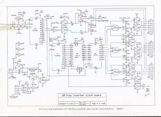
Ok, here is the schematic of the three inverter, 27 step clock board that provides all the required drive signals.
Its all fairly self explanatory except for the mosfet bridge at the top of the circuit. This produces 50 Khz continuous ac power to power all the individual isolated gate drivers through several small 1:1 pulse transformers.
NAND gate U2 generates the drive signals for the zero volt clamps. All data outputs are time coincident coming out of data latch U9, and the 1uS dead time must be provided for in hardware.
Only other thing to note is U4 which is an under voltage sensing chip that holds the main address counter (U7) reset during initial power up and during power down. Holding U7 reset will turn off all the output devices within the 610nS update period of data output latch U9. When reset is released, the sine wave always starts off from the zero crossing point.
This is to provide orderly safe start up and shut down as the +5v supply voltage initially builds up and finally decays. This aspect is particularly important in any inverter.Cheers, �Tony.
mackoffgrid Guru Joined: 13/03/2017 Location: AustraliaPosts: 460
Posted: 06:09pm 17 Mar 2017
Copy link to clipboard
Print this post
Thanks Tony
Only just got my internet back. I was putting all pieces together.
My rough looks very similar to your schematic - no surprise. Though it maybe some of my calcs may differ.
From your data I have 2048 address to step through. (I'm assuming 2048 will also work for 4 transformers?)
So I calculated the clock rate needed is 102400 hz. I selected a 4.096 Mhz crystal and using a 4040 to divide by 40.
I do like how simple the reset is used as a shutdown. I tend to shy away from pulse transformers since I never really worked them and was intending to use isolated power supplies and opto Fet drivers - I'm guessing my way is more expensive. How much can we get those pulse transformers for? Is there a performance benefit?
I can't read most of the writing on the schematic, any chance you could send me a higher res image.
I really can't thank you enough, I'm really getting into this.
Andrew
Grogster Admin Group Joined: 31/12/2012 Location: New ZealandPosts: 9061
Posted: 06:47pm 17 Mar 2017
Copy link to clipboard
Print this post
Yeah, pretty impossible to read. This is the forum software squeezing your image, probably not your actual image.
You can repost as a GIF image(which is not squeezed as much as JPG is), or you could upload to DropBox or similar and post the link.
Looking forward to studying it.Smoke makes things work. When the smoke gets out, it stops!
Warpspeed Guru Joined: 09/08/2007 Location: AustraliaPosts: 4406
Posted: 06:47pm 17 Mar 2017
Copy link to clipboard
Print this post
Sorry about the image quality, I had to scan a one year old printed copy and it has not turned out well at all. I will work on that problem.
My crystal is 3.2768 Mhz which is a readily available frequency. The first counter (U6) divides that down to 102.4 Khz from the Q5 output.
Main counter U7 has ten outputs Q1 to Q11. Eprom is 27C16 which is 2K x 8 that will need to be 120nS version or faster. That all provides 50Hz output. to drive three inverters.
The output latch is clocked at 1.638 Mhz sixteen times faster than the data in the Eprom is changed. The reason for that is so a main counter reset turns everything off as fast as possible.
The four inverter version is identical except the two highest data bits are used to drive an extra NAND gate and extra output drivers.
2K of memory gives a very fine 10uS step resolution, which is far more than really required. If you are going to use multiple lookup tables 1K per table would be quite adequate. 2K is the smallest cmos eprom available, so I just decided to use all of it because it was there.
The upper gate drivers for the bridge, and possibly the clamps will each require isolated dc supplies. I used pulse transformers because I already had a lot of them. Those 1 watt isolated dc/dc power modules would be smaller and cheaper than pulse transformers anyway. I just used up the junk I already had on hand.
Its actually not all that complicated, the only really painful part is calculating the eprom data. Originally I wrote a program in basic to do it all and print it out. A spread sheet would be another way. A scientific calculator might also work.
The battery version with a microcontroller had fifteen 1K lookup tables, and 1K of eprom reserved for the actual running program.
Edited by Warpspeed 2017-03-19Cheers, �Tony.
Warpspeed Guru Joined: 09/08/2007 Location: AustraliaPosts: 4406
Posted: 07:02pm 17 Mar 2017
Copy link to clipboard
Print this post
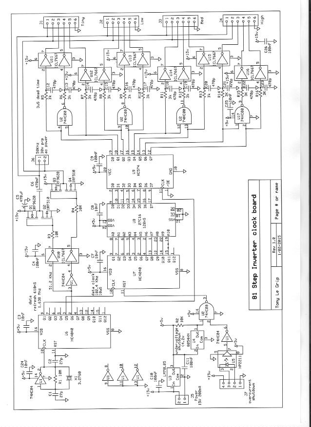
Ok here is the 81 step GT racing version. Its identical, and the above eprom data will work exactly the same.
Cheers, �Tony.
Warpspeed Guru Joined: 09/08/2007 Location: AustraliaPosts: 4406
Posted: 07:08pm 17 Mar 2017
Copy link to clipboard
Print this post
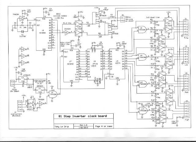
Lets see if rotating it scrunches it up.
Cheers, �Tony.
mackoffgrid Guru Joined: 13/03/2017 Location: AustraliaPosts: 460
Posted: 09:10pm 17 Mar 2017
Copy link to clipboard
Print this post
Thanks, much clearer.
Your xtal frequency is much better, simpler logic.
I was (is) umming and ahhing about whether to use the eprom method or ucontroller (which is much simpler). I am drawn towards the old school eprom method but still add a ucontroller to do regulation addressing and other wizzbang stuff.
All very simple, I like it.
I was going to have a go at working out the values in a spreadsheet, but I did wonder if writing a program would do a better job - we'll see, get the board going first.
I may as well use a 27c256 which will give me 7bit addressing (128 steps) or double if 27c512 is used, probably at the same price. I could use U7-Q12 state change as an interrupt to possibly change regulation Addresses.
My present battery bank is 8 x Winston LiFePO4 (almost 5 years old, and doing well). I top them to kiss 28v then drift down to and maintain 27v all day, almost never drops below 26v except first thing in the morning and if I put the kettle on it may go down to 25.8V . So I dont exactly need a wide regulation range. If my thinking is right, I think I'll shoot for a sweet spot (best sine) for 26.5 Vbatt to translate to 240Vac (best sine). So I think a regulation of 25v to 28v in 100mV steps and use a controller to do the addressing, but where the reg.address of zero is max vBat pattern and go in reverse order.
cheers
Andrew
mackoffgrid Guru Joined: 13/03/2017 Location: AustraliaPosts: 460
Posted: 09:33pm 17 Mar 2017
Copy link to clipboard
Print this post
Tony
Is there much need for large capacitors (as the PWM inverter do) ? I was thinking that the average slow speed would allow for perhaps virtually none or just enough to help the quickest and lowest power inverter?
Warpspeed Guru Joined: 09/08/2007 Location: AustraliaPosts: 4406
Posted: 09:34pm 17 Mar 2017
Copy link to clipboard
Print this post
If you are not flogging your Lithiums hard, a single lookup table might be all you need. Sure the mains voltage will go up and down a bit, but so does the grid.
I cannot remember exactly how my microcontroller software worked, but one mains cycle is 20mS. If you have a 1K lookup table, that means new data on the output port every 20uS approximately. If you have a 2Mhz (500nS) instruction cycle, that is 40 cycles of code between each write to the output port. Its not a lot, but if you write a nice tight program in assembler it should be more than enough.
If you have a microcontroller there you are familiar with, and the means to program it, its going to make things a lot easier. If you have absolutely nothing, the hardware approach is probably quicker.
If you are planning the multiple lookup table regulated output voltage approach, you will definitely need to program your own eproms.
If all you want is a simple single lookup table, I already have all the eprom values for 81 steps that same table also works for 27 or 9 steps. Cheers, �Tony.
Warpspeed Guru Joined: 09/08/2007 Location: AustraliaPosts: 4406
Posted: 09:45pm 17 Mar 2017
Copy link to clipboard
Print this post
You need to realise that the ac current in the load has zero crossings and rises to a peak, and that is reflected directly into current drawn from the battery. It too is pulsing on and off at 100 Hz.
Now if your inverter is up close and personal with a very low impedance battery, very good. If its located a long way, or your battery or battery wiring has some significant resistance, a very large capacitor right at the inverter will really help things a lot.
The requirements will not be that much different to high frequency PWM. Its all a lot easier to do with a higher dc voltage whatever you are planning.
Cheers, �Tony.
Warpspeed Guru Joined: 09/08/2007 Location: AustraliaPosts: 4406
Posted: 10:08pm 17 Mar 2017
Copy link to clipboard
Print this post
Mains regulation does not seem to be that critical. Most important things have voltage regulators, and voltages around the world vary from 220v in the US to 230v in Europe, to 240v in oz.
I have not found anything here that will not work at 200v, although LED lights do dim slightly. All my major appliances and electronics work fine at 200v and up to 260v.
My system here runs about 242v when driven by solar during the day. When the sun sets, it automatically reverts to a grid powered rectifier that drops the mains voltage to around 210v to 220v at night. When the sun rises so does my voltage.
That has worked fine like that for almost a year. There is no practical reason to very tightly regulate the output. I would think an unregulated inverter would work well enough with a lightly loaded higher voltage lithium battery. Not with a low voltage lead acid though.
Try it first with one lookup table and see how that goes. If it falls short of expectations, it might only require a very few lookup tables to fix the problem.
My microcontroller original was for lead acid batteries that worked between 10v and 15v a pretty wide input range. Cheers, �Tony.
mackoffgrid Guru Joined: 13/03/2017 Location: AustraliaPosts: 460
Posted: 10:14pm 17 Mar 2017
Copy link to clipboard
Print this post
I agree, I'm not that fussed about the regulation.
Tinker Guru Joined: 07/11/2007 Location: AustraliaPosts: 1904
Posted: 12:26am 18 Mar 2017
Copy link to clipboard
Print this post
Hi Tony,
All this looks very intriguing to me. If my present inverter build does not soon turn into a trouble free unit I may seriously think of going down your method which, although electronically more complicated, seems to be far less troublesome. Certainly, being retired, time spent is no problem.
Anybody thinking of developing a neat PCB of the schematic you posted above? It might be worth while to have it then made in China, like the one oztules came up with for his inverter version.
So I have a question. There are several large toroid transformers in my workshop waiting to be used. I can re wind them too, lots of copper wire left over.
#1 = 3KW Aerosharp toroid, it has a 230V winding. #2 = 2.5KW Latronics toroid, it has also a 230V winding. #3 = 1.2KW Latronics toroid, 230V winding. #4 = 80W toroid, no windings.
What could I build with these & what total power? I would run it from my 16cell lithium battery. its terminal voltage is between 54 & 56V. Klaus
mackoffgrid Guru Joined: 13/03/2017 Location: AustraliaPosts: 460
Posted: 01:06am 18 Mar 2017
Copy link to clipboard
Print this post
#1 and #3 would be useful for the first two transformers.
I'll certainly be drawing a schematic and pcb in EagleCad unless someone else does. (I'm no genius with pcb design like some but I've done my fair share) The smaller cores I need I was going to buy from a mob in SA.