
|
|
Forum Index : Electronics : time to build a replacement inverter
| Page 1 of 8 |
|||||
| Author | Message | ||||
| poida Guru Joined: 02/02/2017 Location: AustraliaPosts: 1480 |
So, after a little more than 2 years the Victron 3000VA Multiplus inverter has died. Evidently the warranty is 2 years so I have to congratulate the designers for the near perfect product obsolescence. Have a few drinks on me, guys. Anyway, time to make a replacement. I will be using the 3000VA Aerosharp toroid and the aliexpress inverter board I posted a "wanted" entry here, looking for another 3000VA Aerosharp toroid. I think I need to keep experimenting with this stuff so I need a replacement for the one I will use in the home inverter. I hope someone here can help me out. Ebay and Gumtree have nothing at the moment. The inverter I am building will spend a lot of time at power levels less than 1000W. I wrote on this subject at length here I think I will attempt a modest unit with good headroom for when fridge motors start up etc. And so today I report I have rewound the primary to suit 48V supply and rewound the aerosharp choke core with thicker wire. I cleaned out all the welded bolts and crap from the aerosharp steel box. Tomorrow I fit the inverter board, 240V GPO and 10A contact breaker. wronger than a phone book full of wrong phone numbers |
||||
oztules Guru Joined: 26/07/2007 Location: AustraliaPosts: 1686 |
The first one we did runs at very much more power levels than that, and has done 4 years so far That was a power jack conversion.... I would like to think it will be blue skies for you too. I have run a few boards that you refer to, and they easily ran at spec. They will start anything you throw at them compared to the victron... in fact streets ahead. I ran the big welder off one of them to try to break it... I did, but I was on the top setting trying to upset it... mine were the 90 dollar ones, that used to220. The hy4008 ( looks like on yours) can do 16-20kw in the ozinverter for start ups. (5hp induction motors) In normal operation with a decent tranny, you should easily exceed your requirements. Do the transformers in the victron offer any solice? .....oztules Village idiot...or... just another hack out of his depth |
||||
| poida Guru Joined: 02/02/2017 Location: AustraliaPosts: 1480 |
Oz, the transformers are tiny. Think 2 transformers, smaller than 1000VA Aerosharp units. The Victron starts up fine and runs for about 3-4 minutes then it dies with lots of hum, overload light and maybe if I'm lucky under voltage light. This with zero AC output load. I suspect it's the mosfets and or gate driver boards. Inside the box it's a wonderland of through hole discrete design. I will give it a week or so, to wait for the disgust to abate, before I consider hacking the be-jesus out of it with an aliexpress inverter board, it's own or some other choke and it's transformers. Kick the rest into the workshop parts heap. Maybe I'll do a tear-down so we all can have a good laugh.. I rewound the 48V primary with 4 x 6mm2 cable. I do not have anything bigger. This will be OK for my expected loads. I will have temp sensors on both the transformer winding and the mosfet heatsinks, leading to the Arduino to determine if things are OK or too hot. wronger than a phone book full of wrong phone numbers |
||||
| poida Guru Joined: 02/02/2017 Location: AustraliaPosts: 1480 |
The transformers inside the Victron are very much like these (Gumtree) I think someone else has a failed Victron Multiplus wronger than a phone book full of wrong phone numbers |
||||
| oztules Guru Joined: 26/07/2007 Location: AustraliaPosts: 1686 |
They will need some big inductors, or capacitors to use them for battery charging... or they will blow every fuse in the line to the grid if the batteries are any where near flat... the currents would be very high..... this would be the last transformer design to ever call a battery charger transformer without supporting circuitry. You may be scratching to turn it on consistently without blowing the house fuses without some sort of soft start too. ..........oztules Village idiot...or... just another hack out of his depth |
||||
| Warpspeed Guru Joined: 09/08/2007 Location: AustraliaPosts: 4406 |
[quote]The inverter I am building will spend a lot of time at power levels less than 1000W.[/quote] Then you probably do not need an inverter transformer that will be rated at much more than 1,000W. The rest of the inverter needs to have sufficient grunt to support very high short term loads, particularly for starting up refrigerators and freezers. That means sufficient MOSFETS and an inverter choke to cope with high short term loads, but the actual inverter transformer itself only needs to be rated for a more spaced out average maximums that occur typically during the early evening domestic peak consumption. Your logger is fine, but what you really need to know is what peak demand is. Motor starts can last for around one second, and my own refrigerator needs almost 3Kw to get going, even though the rated running power is only 127 watts, and 250 watts during the infrequent automatic defrost cycle. Anyone reading the refrigerator specs might assume a 250 watt inverter would happily run that refrigerator, it most certainly would not. But an inverter rated at 3Kw continuous power output would be overkill, although its probably necessary to start the thing up regularly over long periods without eventual disaster. If you are home brewing something, you can take all this into account and build in a big safety margin for short term peaks, but designing for a much lower long term average power output level. At night the loads are usually absolutely minimal, so very high low load efficiency really becomes important. What this all comes down to is lots of MOSFETS, a smaller inverter transformer and the heatsink needs to be designed with very high thermal mass, but less fin area. Its a heat SINK, not a thermal dissipater. You will do much better with a few Kg of aluminium in this type of application than with a fan. Commercial inverter designers have huge problem (I used to do this professionally myself) they have no idea of how their product is going to be used or what is going to be connected to it. But if you are doing this for yourself, you can build something especially good that will work wonderfully well for what you expect it to do. And there in lies the answer. But if you know exactly what you want, and treat it with some respect, you can come op with something you can be very proud of, and be completely happy with. Cheers, �Tony. |
||||
| poida Guru Joined: 02/02/2017 Location: AustraliaPosts: 1480 |
Warpspeed thanks for your thoughts. I have only two transformers. one 1000VA and one 3000VA. I know my power loading and I choose the 3000VA over the 1000VA. Testing has shown to me that the 1000VA saturates at 1000W output (or input) I will not consider using this since I have records of extended periods of time where the Victron was supplying power levels near 1000W. To run a transformer at saturation for minutes to hours is not going to lead to a happy ending. Idle current during bench testing the 3000VA with 27V supply are of the order of 0.5A or 15W. I can live with this. Typical overnight power levels were 250-300W so the 15W idle is only 5% or so. I have 3 fridges, a tropical fish tank and many electronic things on standby. What is 15W idle loss to me. I agree that mosfets run better when cold. I have read and clearly understood the specification documents of typically used mosfets and the thermal de-rating is clearly a large factor (in both failures and design considerations) I will be sticking with the inverter board's too small heatsinks for now. Designing from scratch I would first choose huge heatsinks and build things around that. But I am not designing from scratch. I will be monitoring the heatsink and transformer temp continuously and in a few weeks it will be clear if the OEM heatsink is up to the task in my application. wronger than a phone book full of wrong phone numbers |
||||
| Warpspeed Guru Joined: 09/08/2007 Location: AustraliaPosts: 4406 |
Power does not saturate a transformer, applied voltage does. Its not generally realized that the flux in a transformer hardly varies at all from no load to full load. What does change is the current flow through the windings, and the heat and temperature rise that creates. The only thing that limits a transformers power is temperature rise. And you can run huge overloads for very short periods without any problems at all, as long as the transformer does not overheat. Check out the specifications for commercial transformer welders, you will see something like "rated at 220 Amps 30% duty cycle". Nobody welds continuously for hours on end non stop, so its a perfectly reasonable way to rate any welder. A home inverter likewise may only have to sustain very high power for fairly short periods. That is not going to saturate the transformer, but it might get a bit hot. Transformers are almost always rated for continuous full power, but that is completely unrealistic for a home inverter. Cheers, �Tony. |
||||
| oztules Guru Joined: 26/07/2007 Location: AustraliaPosts: 1686 |
Yes, heed Warpspeed in this,once you have established that you are not in saturation at no load.. more load will NOT repeat Not saturate the transformer, only a change in voltage (emf) or frequency will affect the saturation point. It is a popular misconception.. and comes from the idea that amp turns is what contribute to the saturation which must inevitably follow high loads.. it is wrong If you look at the equations. you will see it is frequency and voltage dependent... not current. Yes amp turns creates the field... but once you have established that no load is not at saturation.. it is not going to saturate with extra load.... it is only an IR problem. The extra amps is in the wire of the primary mmf working against/with the secondary mmf... that is where the power is transmitted between the coils...the core is an innocent bystander in this now. Once the idle current is established, all losses should be in the I^2 R of the system I think. If that is wrong I expect Warp will set me straight. ( will be interested if I misunderstand this) ...oztules Village idiot...or... just another hack out of his depth |
||||
| Warpspeed Guru Joined: 09/08/2007 Location: AustraliaPosts: 4406 |
Oz is quite right, once you have your transformer wound, and are running at a respectably low flux density, that will give excellent low load efficiency and go a long way towards solving the current inrush problem. From there, its all just the I^R copper losses in the windings with rising load. Adding more turns (per volt) on both the primary and secondary will increase the wire length and very slightly reduce the efficiency at full flat out power. But it will also significantly improve the inverter efficiency at very low loads, which is of much more importance in a domestic inverter, which spends most of its time running at very low average power. What we are trying to do is wind a transformer that will be more ideal for our own rather unusual requirements, and that can be done very successfully. Cheers, �Tony. |
||||
| poida Guru Joined: 02/02/2017 Location: AustraliaPosts: 1480 |
Thanks to both Warpspeed and Oztules for your comments. You clearly care enough to want to spend time and effort in helping me understand things. I have finally got the time and enthusiasm to complete the inverter. 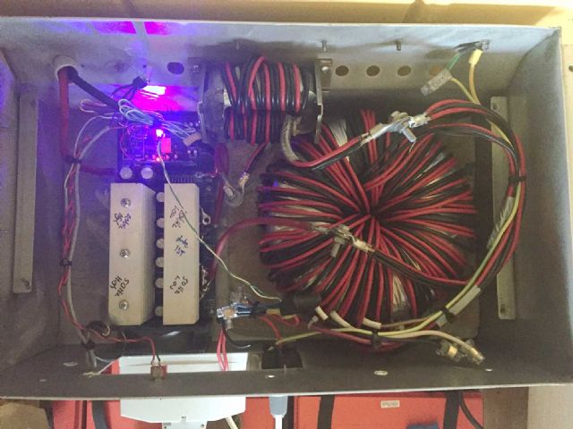 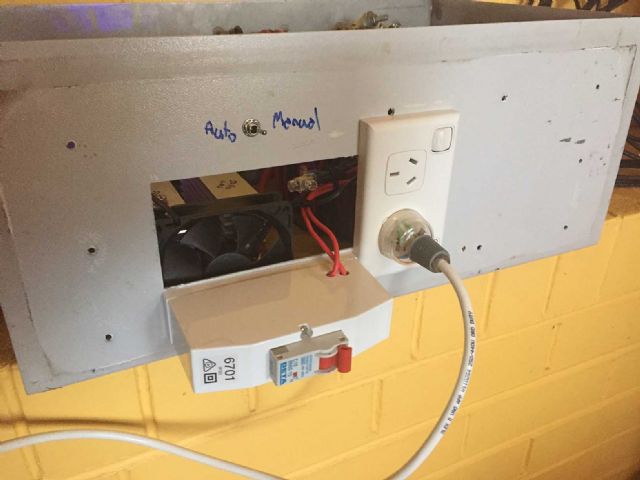 It does the job. The 10A 3 core output has 3 fridges, a fish tank, modem and router, imac and UPS, 2 laser printers, 2 macbooks, 3 monitors and more hanging off it. As at the time of writing the inverter DC input current is 7.3A @ 55V so that's 400W 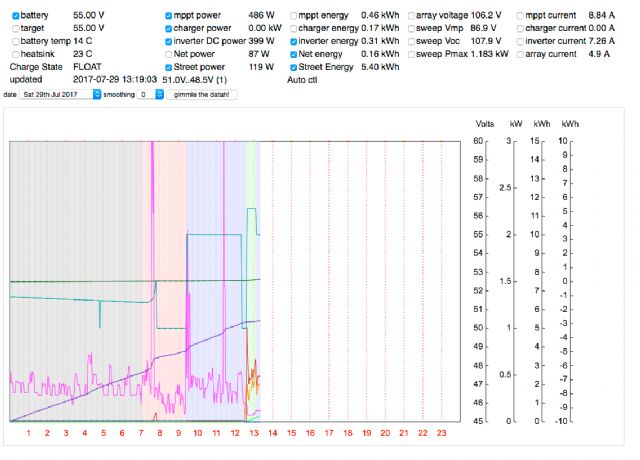 The heat sinks are still at ambient temp, the inductor winding the same as is the toriod's primary. The primary is 4 x 6mm2 copper. The inductor is 3 x 6mm2. I2R losses at 400W would be small enough to accept. I've been thinking over the possible reasons why the Victron kicked the bucket. (Recall it runs fine for 5 minutes with zero load then starts to hum loudly with overload &/or low Voltage LED's lit up. I can cycle this as often as I want) I use a Latronics Automatic Transfer Switch (ATS 40Amp) to automatically switch over the above detailed loads from inverter to street power when the battery voltage drops to a set point. And once the battery gets enough charge, the inverter is switched on again and the ATS senses this and changes over the AC source from street to inverter. Possible failure scenario: Should the street AC phase be inverted compared to the Victron AC output , the switch over even may be putting large current or voltage pulses into the Victron inverter. This might have damaged the mosfets or their gate drives. The Victron did not have any street AC phase sense connected, and I think it has no facility for this anyway. I will find out soon enough when I re-install the ATS and either see magic smoke or not from the inverter board. At least the inverter board is repairable. The equipment connected to the inverter output can in fact handle interruptions of the order of seconds to minutes. NO need to have the immediate 20ms switchover as provided by the ATS. It might be time to build a slow changeover ATS or hack the Latronics unit to change over with a (say) 5 second zero AC output period. wronger than a phone book full of wrong phone numbers |
||||
| oztules Guru Joined: 26/07/2007 Location: AustraliaPosts: 1686 |
I use a transfer switch from england, but which is in fact 4 normal breaker box switches from a normal AC power board,, stitched together.... so they switch very fast when over the center point. That switches hard grid to hard inverter and has done for a long time now. How it would go with 20ms I don't know, as this switch is very very fast. Lights hardly flicker, and it may be as low as 20ms or even less... don't know. This has been done with loads up in the 5kw range, and the inverter has never flinched... so thats as much as I can tell you about the 8010 in that situation. It works, and thats a good thing. .........oztules Village idiot...or... just another hack out of his depth |
||||
| Warpspeed Guru Joined: 09/08/2007 Location: AustraliaPosts: 4406 |
If the lights go out here, I prefer to work out exactly what has happened, and know why, and throw the big switch myself. Anyhow, I finally figured out a cheap and simple way to further protect my Lithium battery from an ultimate catastrophe. I now have a two pole DC circuit breaker coupled up to a shunt trip coil. That operates from a programmable digital voltmeter that has two alarm relays. I have programmable undervoltage and overvoltage thresholds in 10mV steps. It works really well. As far as I know nobody else has done it this way. This works quite independently to the main BMS (software), and voltage levels in the charger and inverter (analog). So it adds a third layer of ultimate protection for both under and over voltage, as well as any unlikely overcurrent. Cheers, �Tony. |
||||
yahoo2 Guru Joined: 05/04/2011 Location: AustraliaPosts: 1166 |
I have tried to trip the 40Amp latronics transfer switch up going back and forth from an inverter to generator under load but it seems to always sort it out and work just fine. I'm confused, no wait... maybe I'm not... |
||||
Madness Guru Joined: 08/10/2011 Location: AustraliaPosts: 2498 |
My old trace Inverters had a brilliant system where it synced to the generator or mains and then closed the relay. This results in totally seamless transfer, I doubt you would see it on a fancy cro apart from seeing the frequency change to match up., There are only 10 types of people in the world: those who understand binary, and those who don't. |
||||
| Warpspeed Guru Joined: 09/08/2007 Location: AustraliaPosts: 4406 |
Yes, jumping out of airplanes with a parachute works too. Until one day it does.'t. Cheers, �Tony. |
||||
| poida Guru Joined: 02/02/2017 Location: AustraliaPosts: 1480 |
I pulled apart the Victron Multiplus 3000 inverter/charger. Let's see how many photos I can post... The useless Blue box. 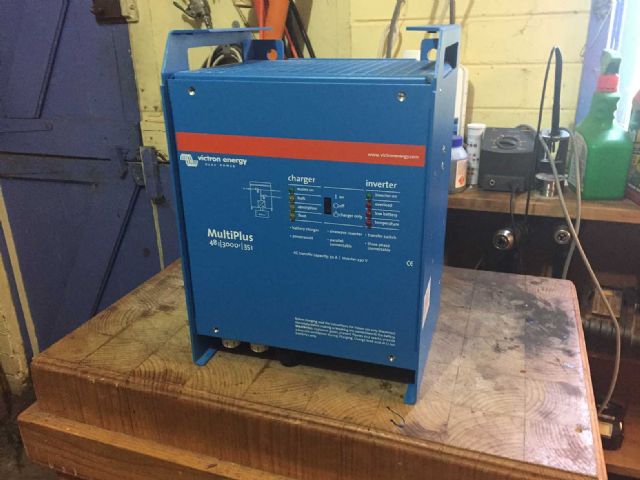 main control board. All through-hole. 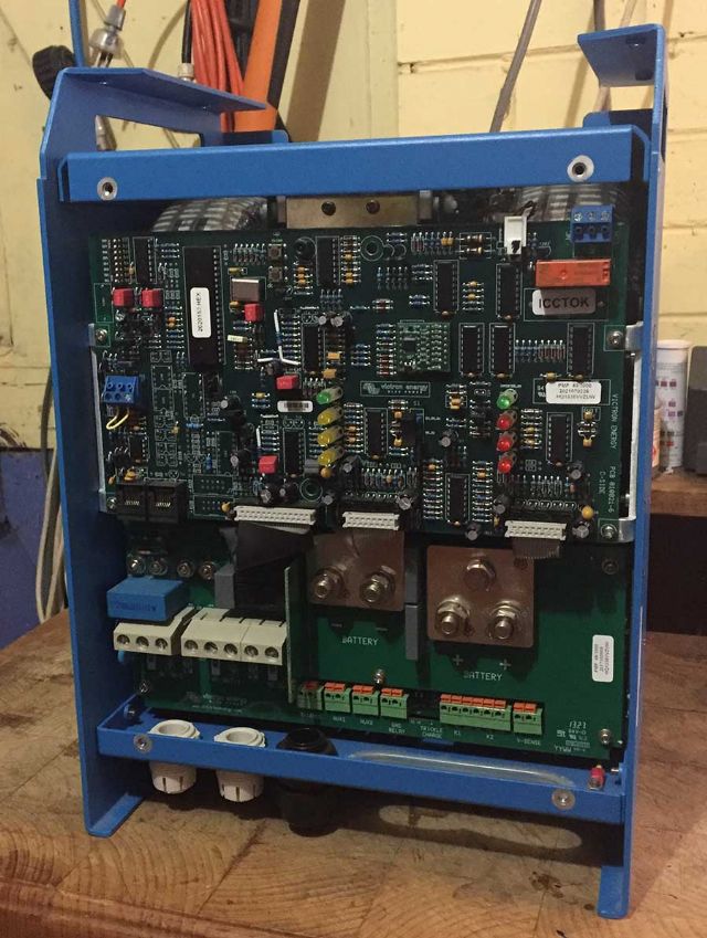 some bodge jobs, front and back of board. 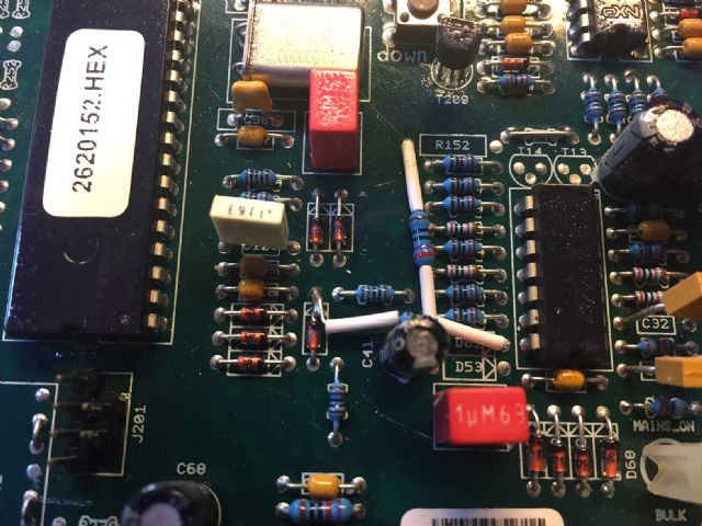 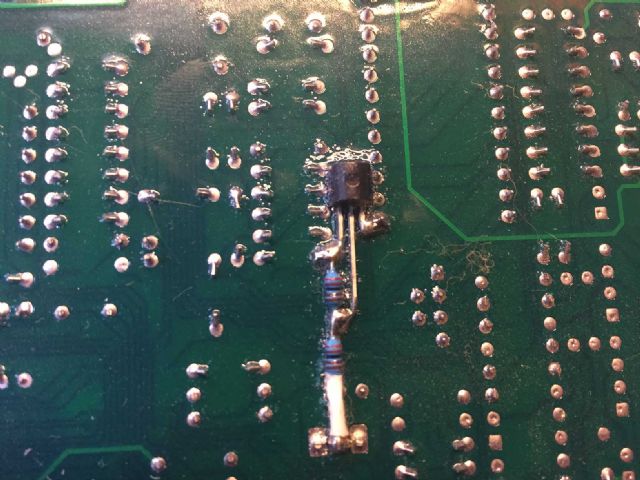 after control board removal, unit upside down. 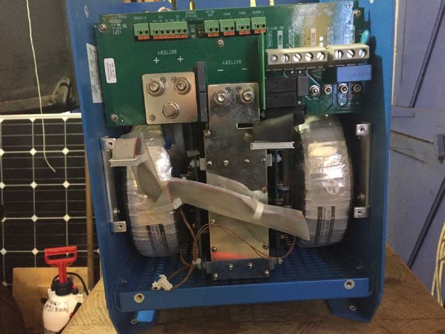 view from top, yet more discrete stuff. 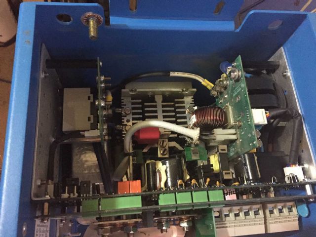 The view of the back side of it. This is the AC switching and charger switching control 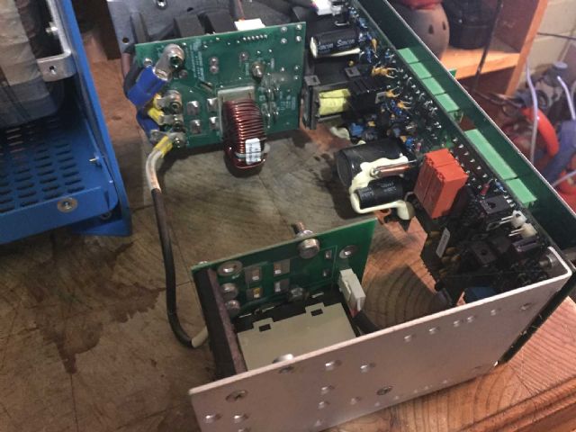 At last we get to the mosfet full bridge and transformers 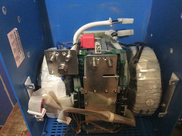 I don't recall subletting the inverter to this guy.. 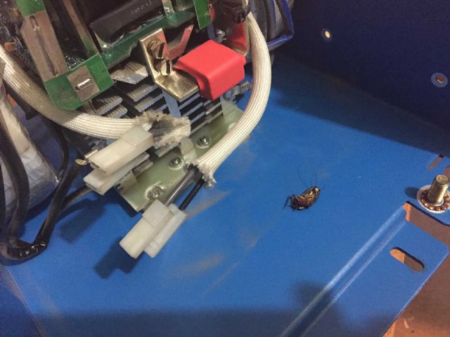 one half of the full bridge gate drive. Oh my God. 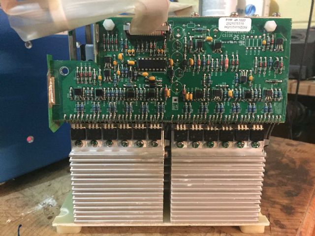 (we now achieve great gate drive via $7 chips and a few components.) 10 big DC bus caps all in a row. 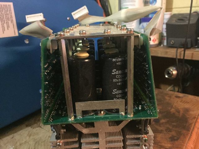 4 rows of 12 mosfets. Fairchild (OnSemi) F75646p mosfets datasheet 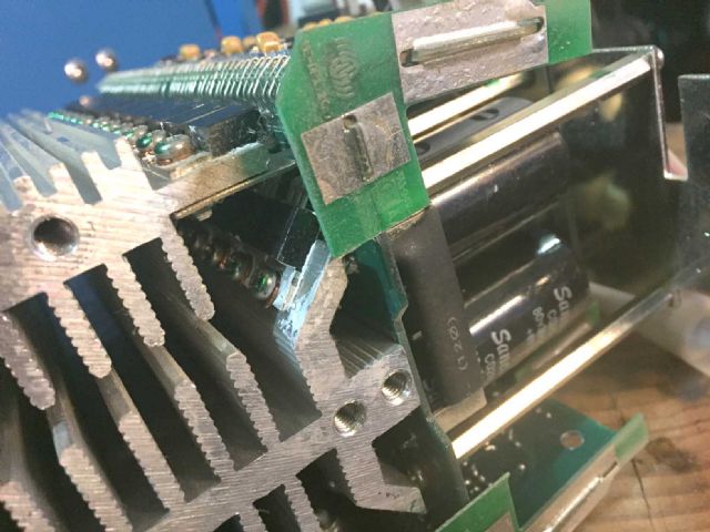 The star of the show, at last. The transformer(s)  only wound 1/2 of circumference, I wonder why. Probably a lesson there. 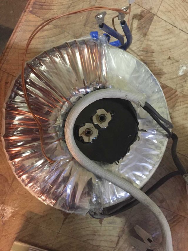 size comparison to a box of Hansons. In the real world these toroids are 1/2 as high and a bit smaller in diameter than the 1000VA Aerosharp. 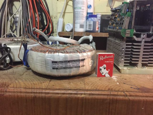 The inverter used one only transformer for low loads and switched in the second one for higher loads. There is no way I will spend any time looking at why it failed. Also, I don't have the skills to understand let alone repair this complex lump of rubbish. To my eyes it looks 15 years old obsolete. The transformers might be worth keeping. Time to get back to working on the important things in life. wronger than a phone book full of wrong phone numbers |
||||
| oztules Guru Joined: 26/07/2007 Location: AustraliaPosts: 1686 |
ditto You have seen how simple it can be ....oztules Village idiot...or... just another hack out of his depth |
||||
| poida Guru Joined: 02/02/2017 Location: AustraliaPosts: 1480 |
I was wondering about the 1/2 circumference wound primary on the two transformers. the reason is here http://ieeexplore.ieee.org/document/6473895/ "Toroidal transformers are commonly used in power electronics applications when the volume or weight of a component is at a premium. There are many applications that require toroidal transformers with a specific leakage inductance value. A transformer with a large (or tuned) leakage inductance can be used to eliminate a (series) filter inductor. In this paper, a procedure to control the leakage inductance of toroidal transformers by leaving unwound sectors in the winding is presented." you can read it here And that 'splains why I did not see any primary inductor. It's not needed. My LCR meter shows about 204uH at 100Hz into the primary with the secondary shorted. I hooked it up to the prototype inverter board and it runs fine (and very quiet) without a primary choke. At 48V DC it needs 0.2A at idle and 230VAC output. 9.6W not bad. With a 166W load, I find 93% efficiency but given the small primary wire area I think things will go downhill fast with +1000W loads. There are 2 x 2.3mm diameter single copper wires for the primary. This is 8.3mm2. When both transformers are running it's 16.6mm2 Not a lot where we come from. wronger than a phone book full of wrong phone numbers |
||||
| oztules Guru Joined: 26/07/2007 Location: AustraliaPosts: 1686 |
I'm not sure about this. The W7inverters had very leaky transformers, and had thoroughly terrible ( 5kwh/day ) losses. It is why I originally went to torroids... and low and behold... it made no difference to the idle currents. It was not until I played with the inductor is series with the primary, that things changed for the better..... the leaky ones were every bit as bad or worse than the torroids. So I don't believe the leakage is of any consequence to idle losses... it certainly is to o/load of the fets. The the big leaky ones never bothered the fets with the UPS functions. The leakage seemed to protect them. Later I got some big trannies from the Hydro over here.... EI types, and they behaved the same as the other W7 EI.. without the inductor they were terrible. Overall, the EI seem to be well less efficient on the high power operating, but for lower power, they are quite good..... but must have the inductors to do any good on idle. So leaky just means leaky.... it still benefits greatly from the lousy few uH we use. ..........oztules Village idiot...or... just another hack out of his depth |
||||
| Page 1 of 8 |
|||||
| The Back Shed's forum code is written, and hosted, in Australia. | © JAQ Software 2026 |
