
|
|
Forum Index : Electronics : time to build a replacement inverter
| Author | Message | ||||
| Warpspeed Guru Joined: 09/08/2007 Location: AustraliaPosts: 4406 |
All this needs a proper design approach, and there are several very basic requirements that must be fulfilled if we are not going to have some very serious problems and limitations. Mickey Mouse PWM works fine at low power. As we start to scale things up we need to be a bit more careful. And a proper design approach is well worth the trouble of investigation. Just making the thing inefficient so it does not blow up is not a great solution. We have significant power being generated at two widely spaced frequencies 50Hz and at the PWM switching frequency. We want the lowest possible attenuation (losses) at 50 Hz and the highest possible attenuation to filter out the PWM switching frequency and its higher harmonics. That is all fairly straightforward. So it has to be a low pass filter of some kind, but we also need to think very seriously about the input impedance of this filter we are building. It needs to be a very high input impedance at 50Hz, and also a very high input impedance at the PWM switching frequency. A low filter input impedance at 50Hz will just absorb significant no load power for no useful purpose. A low impedance at the switching frequency is very likely going to create some fearsome problems for our mosfets in the form of high current spikes. If we get all of this wrong, we can have both a very inefficient inverter and one slightly more prone to spontaneously blowing up. Its not that difficult to do if some fairly logical design steps are followed. The very first thing to look at is the bare output transformer. There is first the requirement for the right primary/secondary turns ratio, plus sufficient copper to carry the full load current without it bursting into flames, but also we need to think about transformer losses. Magnetizing current should be minimised, and so must leakage inductance be minimised, because any leakage inductance in the transformer is going to drop a lot of voltage at 50Hz at full flat out load. In other words it reduces the voltage regulation of the transformer at maximum output power. We still need to have some series inductance, but NOT within the transformer itself, that is the worst way to do it. Having wound our ideal toroidal transformer, it will have a very high inductance because of the quality and permeability of the grain oriented silicon steel. We also reduce the flux density as much as we can, and we use full layered windings to get the best possible coupling to reduce leakage inductance. We then resonate this transformer with a capacitor, ideally in the primary, but for a low dc voltage battery type inverter its much more practical to place the capacitor across the secondary. If its a high voltage grid tie inverter, the primary is probably the better place for this capacitor. If our transformer has excellent coupling and very low leakage inductance, it does not really matter much which side we fit our resonating capacitor. Primary and secondary will be intimately coupled and the capacitor will reflect from one side to the other according to the turns ratio squared, If the transformer has very poor primary/secondary coupling it is not going to work as well as an efficient tightly coupled resonant component. It would be nice if we could resonate it at exactly 50Hz, but that would have the effect of causing a massive buildup of resonant energy at zero load. The output voltage would rise uncontrollably at no load and be very difficult to tame with voltage feedback. So we resonate it at exactly 1.5 times the frequency (75Hz). This tends to damp out the troublesome no load voltage buildup peak, as each cycle is out of phase with the next cycle, there is a kind of self damping going on. But it still behaves as a very effective two pole low pass filter. At 50Hz it will have a very high input impedance, higher than with just the transformer by itself. The resonating capacitor creates circulating energy, like a pendulum or a flywheel that is very efficient at transferring energy at 50Hz, but has a very high and rising attenuation with increasing frequency. That would be fine but for one new problem it creates. The impedance of the capacitor shunting the transformer keeps falling as the frequency rises. At the PWM switching frequency our transformer will now look like a dead short at the primary. So we need to add an external series choke to that, to raise the input impedance back up at higher frequencies. This needs to be external to the transformer, or else attempting to resonate the transformer at 75Hz will not be as effective. How much inductance do we need ? We need enough series impedance at the PWM switching frequency to reduce the high frequency ripple current. Now as we make this choke larger and larger, it begins to add some significant series impedance at 50 Hz resulting in a power loss. So there will be an optimum size that greatly attenuates the PWM switching frequency without adding any significant attenuation (loss) at 50Hz. There is also another problem to be mindful of in all of this. Our series choke will now resonate with our transformer parallel resonating capacitor at some particular frequency. At that series resonance, the input impedance to our filter drops very low. Destructively low ! We need to place that savage impedance dip well above 50Hz, and well below our PWM switching frequency. Ideally spaced the same number of octaves from each. So we figure out that 20Khz is 400 times 50Hz. Take the square root of 400 which is 20. We size our series choke to resonate at 20 times 50Hz (1Khz) and 20 times below our 20Khz PWM frequency. If we are switching at 25 Khz, it would be 25,000/50 = 500 Square root of 500 is 22.4 And our series resonance 22.4 x 50Hz = 1,118 Hz roughly. Now if our transformer resonating capacitor is wired directly across the primary, we size our choke to resonate with that capacitor at 1Khz (in this example). If our resonating capacitor is wired across the transformer secondary, it will reflect back directly into the primary as a much larger capacitor equal to turns ratio squared times the capacitor across the secondary. This will work fine because although there is now a very nasty dip in our filter input impedance at 1Khz, the impedance at both 50Hz and 20Khz will both be very high. Which is exactly what we need. There should be almost zero energy present at 1Khz, only a tiny remnant of harmonic distortion of our 50Hz, and nothing at all from the PWM at only 1Khz. If you do it this way you should have no problems, excellent filtering, and very low no load losses. All this needs to be read through several times and thought through very carefully, its rather a lot to digest all in one go ! Cheers, �Tony. |
||||
| Warpspeed Guru Joined: 09/08/2007 Location: AustraliaPosts: 4406 |
Two further thoughts. The Inspire 1.5Kw grid tie inverters follow the above design philosophy pretty exactly. By measurement, the 5uF primary tuning capacitor resonates the transformer to 75 Hz. That funny looking dc choke in the primary is marked as being 2.8mH, but by measurement its a bit over 3mH. The series resonant point of the choke and the capacitor in series works out to about 1.3 Khz, probably less in practice because the inductance is higher. Its absolutely vital that this choke never saturates. It needs to cope with very short term inverter overloads which might be twice the rated full power or even more. The transformer will handle short term overloads with ease, but the choke once it hits saturation, its all over... So designed saturation level of this choke needs to be very generous. The 1.5Kw inspire uses a 200 volt dc bus, so the primary voltage will be about 140 volts rms, and about 11 amps rms flat out. The peak of the current waveform will be about 1.414 times that, say 15 amps. The dc choke goes into pretty hard saturation above about 28 amps, so its designed for about twice the max full load power. Thats probably a quite reasonable safety margin to have. So the dude that designed this 1.5Kw Inspire inverter definitely knew a thing or two. Some of the other commercial inverter designs out there are simply disgusting. Cheers, �Tony. |
||||
| poida Guru Joined: 02/02/2017 Location: AustraliaPosts: 1389 |
At the start of this topic I asked if anybody here could help me find a replacement 3000VA Aerosharp toroid. I received a PM from Mulver with contact info for a certain person who ends up scrapping dead or replaced inverters. I don't want to publish his contact info here since it is public and he may not want the attention. Today it arrived in exactly the condition I wanted (perfect, with 250V winding intact). Thanks Mr X  PM me for contact info. He is a member of this forum. He has (or maybe had) a single 3000VA toroid on hand 2 weeks ago if anyone here is interested and can get more from time to time. The QuickHack3000 (tm) inverter of mine is working as expected. Perfectly. I suspect it is more efficient than the Victron 3kVA for two reasons. First is I am getting longer run times from the cloudy Melbourne skies. Secondly the heatsinks do not get warm enough to run the fan during the sub 1000VA loading it is subject to. I recall the Victron ran the fans continuously at about 800VA and would keep running until loads dropped below 600VA for extended periods. I was curious to see if the fan would ever come on and if it would be effective enough. I tested by running the pool pump in addition to the house loads. This got the fan on after about 10 minutes. It ran for about 20 seconds then stopped. 2 minutes later it's on again for 20 seconds. This is good. Here is my new spare transformer, ready for the eventual construction of a much more betterer inverter using 35mm2 primary cables, good hardware, better component location, professional looking cabling etc. 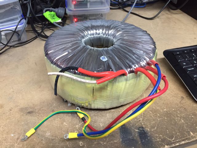 wronger than a phone book full of wrong phone numbers |
||||
oztules Guru Joined: 26/07/2007 Location: AustraliaPosts: 1686 |
Well done... you can rewind the tranny, and use the heap of spare 1.6 to wind the primary with.... as per Madness. Village idiot...or... just another hack out of his depth |
||||
| Mulver Senior Member Joined: 27/02/2017 Location: AustraliaPosts: 160 |
That's awesome poida! Glad you got what you needed! |
||||
| poida Guru Joined: 02/02/2017 Location: AustraliaPosts: 1389 |
It was good going while it lasted. The aliexpress sourced inverter board has blown the mosfets resulting in little bits of TO-247 packaging here and there. The system was not under much load at the time of failure. 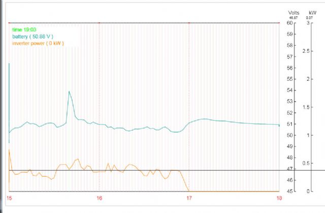 This shows the inverter input power at about 400W (8 Amps at 50V) I will examine the board to see if it's still usable. If so, which mosfets to use? I need a local equivalent to HY4008 but maybe better in some respects HY4008 80V 2.9mR 200A Qg 195nC IRFP2907 75V 4.5mR 209A Qg 410nC I've been learning about dv/dt turn-on and there are some things that you can do to reduce it. I suspect the inverter power bridge is sensitive to this sort of thing. dv/dt effects are proportional to Crss / Ciss HY4008 ratio is 650/7398 or 0.088 IRFP2907 ratio is 500/13000 or 0.038 It's near enough and I would probably increase the dead-time setting on the EGS002 to allow for the longer turn on and turn off. What other parts might be a good fit? wronger than a phone book full of wrong phone numbers |
||||
Madness Guru Joined: 08/10/2011 Location: AustraliaPosts: 2498 |
I have been running at the shortest dead time with HY4008's for the last 4 months nonstop. There are only 10 types of people in the world: those who understand binary, and those who don't. |
||||
| Warpspeed Guru Joined: 09/08/2007 Location: AustraliaPosts: 4406 |
I don't know why, but as Devil's advocate...... As we know, it only needs one mosfet to fail and trigger a total catastrophic failure of the lot, destroying any evidence of the initial cause. Only two possible causes that I can see, voltage breakdown, or a local temperature melt down from thermal runaway. Voltage breakdown could either be voltage spikes originating from stray circuit inductance (non ideal physical layout), or random oxide failure from sub standard mosfets that have poor manufacturing quality control. Temperature meltdown becomes increasingly likely as more mosfets are paralleled and the switching times are not identical or coincident. The first mosfet to turn on, and the last mosfet to turn off in the group can end up having switching losses vastly greater than its parallel neighbours. The more mosfets you parallel up, the greater the potential problem of thermal runaway caused by dynamic unbalance. The theory suggests that the resistance of a hot running mosfet increases, and so that should cause the current to share more equally. That may be true in a dc circuit. If its a switching loss problem, the hot running mosfet resistance increases which generates even more heat. At some tipping point the hot mosfet goes into thermal runaway and then its all over. Because we cannot identify the cause, its not really possible to suggest a cure. If the physical layout looks reasonable, I would first look at the gate drivers and the possibility of using higher voltage rated mosfets of known provenance. That can get rather expensive though, and still may not fix it. But if your low cost "Dragon Brand" mosfets are failing, nothing you can do to the circuit design or the layout is likely to improve things either. Probably the first thing to try would be some higher voltage rated mosfets that will unfortunately have a higher on resistance. If that fixes it with no more blow ups at low power, its very likely to be a voltage breakdown related problem. If that makes it even worse, its more likely to be a dynamic switching problem and the higher on resistance, and greater running temperature makes it even more susceptible to sudden thermal runaway. Cheers, �Tony. |
||||
| poida Guru Joined: 02/02/2017 Location: AustraliaPosts: 1389 |
Oh yes, I like the idea of trying higher voltage devices. The experiment will be a quiet success or a fast track to destruction. I've found IRFP4110, 180A, 100V and 5mR The jump to 100V seems insignificant. IXYS IXFB210N30P3 are 300V, 210A and 14.5mR 5x On resistance and $27 each. I need 12. Over the weekend I will see if I still have a usable circuit board. Then the question of which devices to try will need an answer. (heh, "Dragon Brand") wronger than a phone book full of wrong phone numbers |
||||
| Warpspeed Guru Joined: 09/08/2007 Location: AustraliaPosts: 4406 |
I truly feel your pain, but I cannot really see any other path forward. The only way to try to discover the cause is by changing things and then see what happens. Quiet success or fast track to destruction sums it up very nicely. Another key to all this is making a totally indestructible circuit board that enables very fast and easy mosfet replacement without damaging the board by constant resoldering, or blasting tracks off the board. I am working along those lines myself right now. The basic idea is to use fat busbars bolted to the board (Thank you Klaus!) and also 5mm spaced vertical screw terminal blocks into which TO247 mosfets can be inserted. I have found some good 3 way screw terminal blocks, Dinkle EK500R series. These are rated at 20 amps but will carry current way beyond the legs that any mosfet will carry. https://www.dinkle.com/en/terminal/EK500R-XXP Altronics part number PL2065A and possibly other suppliers that can be found on the internet. The third very useful item are common flat solder lugs ! These invariably have a big end with a 4mm hole, and the tail with a 1mm hole through which you are supposed to insert and solder a wire. The trick is to design your circuit board so that the pin on the screw terminal block lines up with the 1mm hole in the solder lug. And the fat end of the solder lug bolts to the busbar with a 3mm or 4mm screw. You can then lay a solder lug over the copper source and drain tracks, making a neat indestructible current path that greatly increases the current carrying capacity of the circuit board. Its even possible to stack two lugs, or place one on either side of the board. Nothing is going to damage that. Solder lugs are available in many lengths and profiles, and most are fairly short. The longest ones I could find have 0.6 inch hole centres. http://www.ebay.com.au/itm/200pcs-60-2814-51-0030-OSTERRATH-Solder-lug-terminal-0-3mm-M4-%C3%83-4-3mm/263011080994?ssPag eName=STRK%3AMEBIDX%3AIT&_trksid=p2060353.m2749.l2649 Something like this should be able to stand up to any catastrophic failure, and replacing a mosfet then becomes as fast and easy as replacing a fuse. Cheers, �Tony. |
||||
| poida Guru Joined: 02/02/2017 Location: AustraliaPosts: 1389 |
thanks again for your thoughts, Warpspeed. I think failure was due to extended periods of over spec gate voltages (originating from dv/dt), Vds exceeded etc. The heatsinks never got hotter than about 45 C. Continuous loads were less than 1500VA peak. 95% of the time loads were 500VA or less. I have pulled the board out and see 9 of 12 mosfets continuous from gate to source (stuffed, Royally). The board looks fine thanks to on-board 105 Amp fusing which has blown. After this I now get down on my knees and genuflect to the efficacy of fuses. They saved the board. Now, the question is which mosfets to install in their place. I like the IRFP4110. RS Comps does not have stock until 9/9/17 I am open to the option of trying more HY4008 "Dragon Brand" mosfets. Anyone here have 12 they can sell me? I think I will do a few things, all at once. There goes the clear chance to learn things. Oh well, I need an inverter right now. 1/ up-rate the mosfets. Replace all 12. Check rest of board. 2/ install new 105 Amp fusing 3/ customise the EGS002 board so that it provides gate drive producing output synchronised with my 240V AC street supply. No more EG8010 control. Poida Control now. I still think the change over switch of mine can switch at times where large inductive loads feed huge current back into the inverter, depending on the relative phase of the inverter and the street supply. I don't like this. #3 is looking easy for me. I already have a modded EGS002 board which has the EG8010 chip isolated from the gate drive chips. I have flying leads coming from the IR2110 ICs and have cut the shutdown signal inputs (to permit the internal pull-up to permanently enable output). This was hooked up to an Arduino Due running my code with custom dead-time, and a simple feedback control to deliver the required AC output. I will add to this a sample of the street supply (isolated and stepped down to 3V) and then determine a certain phase angle of the supply, comparing it with the PWM 50Hz output and speed up/down as needed to sync up. Only when sync is close will I permit the sinewave PWM to ramp up and run closed loop. I like this idea a lot. The changeover will then be very smooth in all cases now. I ordered another identical board last night so I will be in a position to compare the two approaches over a long term without being inverter-less for very long. I always mod. the EGS002 to cut the shutdown signal to IR2110. Your thoughts? wronger than a phone book full of wrong phone numbers |
||||
| Tinker Guru Joined: 07/11/2007 Location: AustraliaPosts: 1904 |
Tony, the Altronic part you quoted above is only rated at 10 A. But you don't need a right angle version if you do this: 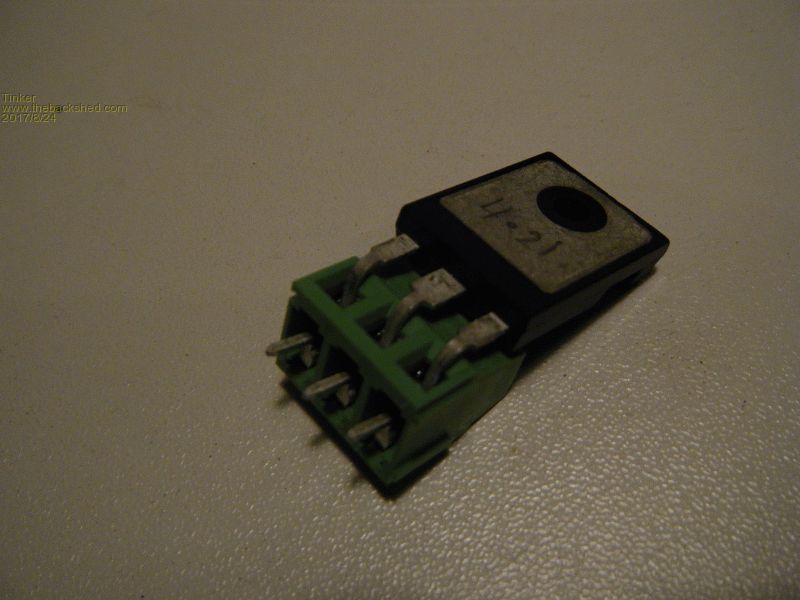 Part # for a 3 way is PL2035A and is rated at 20A, its cheaper too .Regarding the solder lug idea, I just held a magnet to my collection of them and, no surprise, quite a few stuck to it. Tinned steel is not particularly conductive so adding those might improve current capacity less than expected. However, the two packs of lugs I got from RS components did not attach to the magnet, meaning they might be tinned brass. Still not as good as tinned copper though. Klaus |
||||
| oztules Guru Joined: 26/07/2007 Location: AustraliaPosts: 1686 |
Fusing is essential for board coherence after a burn out. Power Jacks did not have this, and you could loose the main and control boards, as the banging and popping went on until it was quiet. I find 2 x 63a AC o/loads seems to work just fine.... never any trace of board stress. Like the synchronising idea, as it will lend itself to using it as the charger as well... and we will have control of how the thing gravitates from one hz system to the next.... very interested in your journey there. 4 x hy4008 will be plenty. Don't know why your board failed, but it will not be from under sized fets. I find 4 x hy4008 ( 16 all up) will get up in the 15kw range without a problem... time after time. I have not had 002 boards out in the wild at any time, so don't know how they run unattended. Quite a few early 8010 units running happily after a year and a half.. so they work long term. The later versions are all doing fine as well at different sites. I have no idea what caused your failure.... I never know what causes fets to self immolate. Following with interest. ......oztules Village idiot...or... just another hack out of his depth |
||||
| Warpspeed Guru Joined: 09/08/2007 Location: AustraliaPosts: 4406 |
Hi Klaus, just checked out the Altronics catalogue. You are quite right, according to them, the vertical P2065A is only ten amps. But the Dinkle data sheet for that part says 20 amps the same as the horizontal P2045A version, so I think Altronics misprinted the current rating in their catalogue. They are both pretty much the same thing, the pins on both are pretty massive, and the whole thing looks mighty tough. The vertical is $1.40 the horizontal $1.30 so not much difference there. Either type will work, it mainly depends which way you prefer the screws to point. My PCB is vertical, my screws are vertical, and the mosfets horizontal with straight unbent legs. Your layout would be perfect for a horizontal board, with both the screws and the mosfets vertical. That is probably the most popular arrangement anyway. Solder lugs are commonly 0.3mm thick, much thicker than the copper traces on the board, so even if they are steel, the current carrying capacity is still greatly increased. Its also possible to directly stack two lugs on top of each other to increase the current rating far beyond what would completely blow out the legs on a mosfet. The big advantage of this is that its cheap and easy, and it looks quite neat when done. I just checked those extra long 0.6" centre to centre lugs I mentioned earlier, they are non magnetic. If using bolted busbars, the busbars or at least the screw heads will need to clear the fairly wide footprint of the screw terminal block. Most lugs may be a bit short to do that easily. Cheers, �Tony. |
||||
| poida Guru Joined: 02/02/2017 Location: AustraliaPosts: 1389 |
Ok, after the failure of the aliexpress board after 2 weeks I thought I'd give another board a go. I did not have any HY4008's hanging around. AND I had stuffed up the first board with inexpert desoldering and hacking. So the new board was installed and it lasted.... (I'm taking bets here...anyone?) Less than a day. Under the same condition as the previous board which lasted 2 weeks. Awesome. AND my wife got to experience the wonder which is "magic smoke" too. Let's enjoy the carnage. Both high and low side fets all blown to the sh*thouse. Load was 1000W DC input. This has 3 x HY4008 fets per leg. Good for "5000W" Chinese watts. 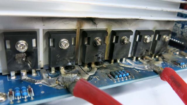 the little 12V buck converter output cap seems to have had a Very Bad Day. 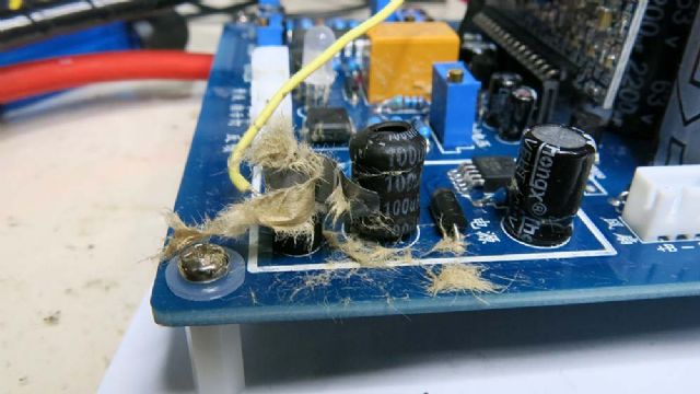 ..which I suspect means Uuuuge volts have been fed back into the control section. Likely the EGS002 board is no longer part of this world. And the comparitor ICs. Finally here is the answer to "What's inside a HY4008?" 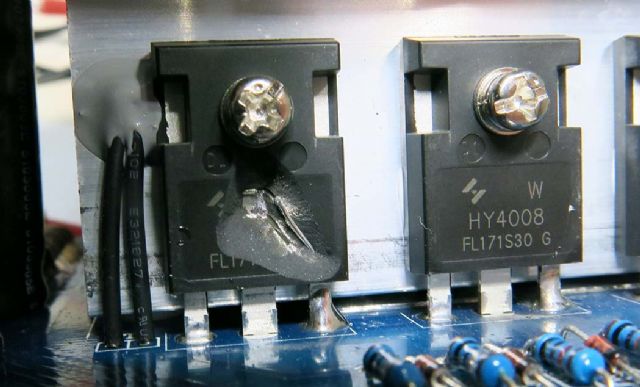 I have on the way from China 20x HY4008, 2 x EGS002 and what I think will be the remedy for all this: a PowerJack 5000W LF inverter. These units seem to be quite repairable when things go tits-up. How long will the PJ last, eh? 2 days? less? All I know is I need to stock up on the PJ power mosfets, opto-couplers, and other things needed to reanimate a PJ inverter. I like the H bridge modular design which makes it easier to replace dead bits without stuffing up circuit boards. I got exactly zero response for my request for a few HY4008. No worries, I have enough to rebuild this second board and I think I will purchase a good many more to have on hand for others who may want some quickly, to be sold at cost. I will have 8 spare in a few days when the first lot of 20 arrive. wronger than a phone book full of wrong phone numbers |
||||
| Tinker Guru Joined: 07/11/2007 Location: AustraliaPosts: 1904 |
Oh dear, Poida, you seem to have joined the club I'm a long time member of. Yes, been there, done that, blowing up HY4008's, and your last picture is very familiar. People hoard their precious 4008's for that reason hence no take up of your plea for some. Mine blew on my own designs though... I suspect these mosfets require a *massive* heat extraction area and, being that close to the edge of the heat sink does not help. Neither does having to place them on insulating washers. With regard to the power jack, my 8KW version has been powering my house for about 2 years with no problems. I bought just the power & control module, wound my own toroid & choke as per the early building your own inverter threads here. I think PJ no longer sells the modules separately - but could be wrong. It might be wise to read through these early PJ threads to avoid more disappointments. Klaus |
||||
| poida Guru Joined: 02/02/2017 Location: AustraliaPosts: 1389 |
Yes, Tinker, what should I look out for? (Never use it as a UPS. Easy, I only will use it as an inverter. Whack a low voltage zener diode across a certain voltage sense feedback resistor? Probably do that too, to keep the inverter running during HV spikes in Dc supply.) I will crack open the case to look for loose nuts and bolts from the assembly process, check tightness of high current connections, etc. Anything else I need to be aware of? The PJ will power the house while I continue to play and learn. My continuous power level is about 600 - 1000W with most time spent lower than 500W. There are large peaks when any of the 3 fridges start up. Oztules rates the PJ LF inverters highly for their surge capacity. So the 5000W PJ seemed about the right size. Of course I will add a temp sensor and readout to monitor transformer and heatsink temps. I have 2 circuit boards for the 6 TO-220/leg bridge inverter system just delivered. The HY1908 fets are due to arrive in a week.see this for pre built boards Let the bodies hit the ground (or rather, Let the Fet's Explode To Bits) I intend to run this board against the 3000VA Aerosharp toroid driven by my Arduino controller with half bridge gate drivers. I figure if I work it so as to permit easy replacement when the inevitable happens I will get plenty of entertainment for about $50 (cost of 2 boards and 30 FETs). wronger than a phone book full of wrong phone numbers |
||||
| Tinker Guru Joined: 07/11/2007 Location: AustraliaPosts: 1904 |
Poida, its been a while since I even looked inside the PJ case (fitted it in an Aerosharp case with a rewound 3KW toroid single core). I do remember the PJ's have a rather high standby current, easily fixed by adding that E65 ferrite choke. The tricky bit with that is to add 3 or 4 turns of a heavy gauge wire into a too small an aperture. I solved this by winding 3x5mm enamelled copper, 4 in parallel I think. But that requires a lathe and a steel mandrel... The inverter on the link you sent is cheap enough but the heat sink looks too small for decent power. I think it requires a decent fan running non stop. Have fun. Klaus |
||||
| noneyabussiness Guru Joined: 31/07/2017 Location: AustraliaPosts: 506 |
Hey poida, may i ask, what " side " blew (if not both) was it the 20khz side or the 50hz side?? Why i ask is i was playing around with isolated drive and a vastly different setup (just cause) and every time the 20khz side would blow and the 50hz side NEVER did... Again, my testing revealed that the eg8010 chip seemed to start with the driver pins doing a "cycle" if you would call it that and was momentary, seems it is in cycle with the h bridge, hence why the 2110s dont mind . If i delayed the startup of the isolated drivers i never had a blow up. Also they were VERY susceptible to noise. To the point i would disconnect my panels (via 2 x 63a breakers ) and it would be a spectacle of blown silicone, yet the very awesome engineered clockmans board i have been using for a month or more now doesnt even blink. .. i have some 75v TVS diodes i can send you if you want, maybe they could help, also some 18v TVS diodes of the same for the driver side?? Cheap insurance... I hope in my rambling i helped.... I think it works !! |
||||
| Madness Guru Joined: 08/10/2011 Location: AustraliaPosts: 2498 |
My inverters gate drive is based on these Chinese 7500W boards they cost twice as much as the 4500W version. I have been running 5 months now with this design and not one hiccup, before that I had blown a lot of FETs with other designs, maybe I just got lucky but seems to me it is more reliable, There are only 10 types of people in the world: those who understand binary, and those who don't. |
||||
