
|
|
Forum Index : Microcontroller and PC projects : MM170 PWM help
| Page 1 of 2 |
|||||
| Author | Message | ||||
Quazee137 Guru Joined: 07/08/2016 Location: United StatesPosts: 603 |
I want to play with the PWM on the MM170 and need a baseline way to build up some testing. the goal is a 0 to 2V or 0 to 3.3V out of a PWM pin. I have never used PWM's and need to know how the Frequency and duty cycle work to make a voltage. The MM170 is reading two 4-20mA loops now making 0 to 20mA is the next part. I started playing with the MM170BP V2 back light getting its voltage. I am going to drive an LM324 to get 0 to 5V feeding 2nd stage 0 to 20mA. The last part I have working with a LM317 and using a 5K pot to 5V/GND with wiper to the 0 to 20mA. I have a gain adj on the LM324 just need the PWM 0 to 2V or 0 to 3V. Any advice would be appreciated. |
||||
| Volhout Guru Joined: 05/03/2018 Location: NetherlandsPosts: 5931 |
Hi Quazeee, Using PWM on the MX170 is very simple. But the PWM output is a digital pulse (not analog voltage). You need to convert that digital pulse to an analog voltage, which can be done by a low pass filter. In simplest form a resistor and a capacitor. Values need to match the PWM frequency. The PWM's in the MX170 MM2 basic are controlled with 0-100% value. To get for 0V that is 0%, For 2V that is 60.6%. I used the PWM in the "Backpack Tracker" project. The basis is: PWM x,freq,value For running PWM 1A at 100kHz, and 2V output, this is : PWM 1,100000,60.6 Hope that helps .... You can look at the code of the backpack tracker to get more insight. The thread is here:backpack tracker IF you want to read analog, and write PWM fast, a high PWM frequency is needed with a suitible low pass filter. Look at the backpack tracker passive low pass filter that is matched to the MM2 100kHz (or 120kHz) PWM output. schematics Of coarse you need to replace the voltage output of the LM741 to a current output (0-20mA). Volhout Edited 2020-09-14 16:59 by Volhout PicomiteVGA PETSCII ROBOTS |
||||
| Volhout Guru Joined: 05/03/2018 Location: NetherlandsPosts: 5931 |
In case you need help with the design of the circuits I may be able to help you. Would need some more information from you though, like what voltage you have available that is higher than 3.3V and 5V (for the backpack). The 0-20mA suggest PLC type sensors and environment, and is designed to work with higher voltages. I.e. 4-20mA sinks can easily require 5V or more as minimum driving voltage. And I need to know the required resolution. The MX170 ADC is 12bit (max). The PWM however is a balance between speed and resolution. At 100kHz (the backpack tracker) the resolution is poor (1% or so), if you need more resolution the PWM frequency must be lower, and the output becomes slower. The lower the frequency, the higher the resolution. For analog temperatures, or DC voltages this may be perfectly OK. Volhout Edited 2020-09-14 17:15 by Volhout PicomiteVGA PETSCII ROBOTS |
||||
| Quazee137 Guru Joined: 07/08/2016 Location: United StatesPosts: 603 |
Volhout It is the frequency part I needed to understand. Here is whats left of the analog way. I cut out all the other op-amps doing some basic adding/subtracting of the two inputs to drive the 4-20mA out. 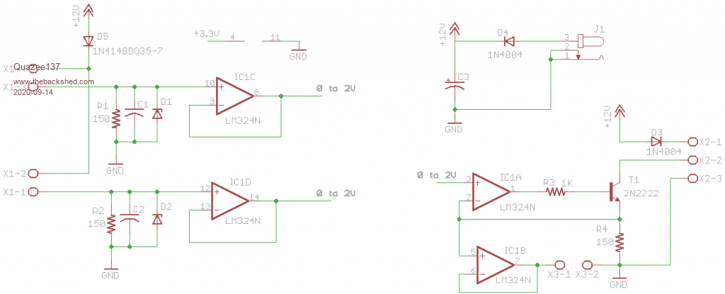 I changed from 5V to 3.3V on the LM324. I wanted to change to the MM170 for its display and touch removing four pots and trimmers. Also can do much more math wise this way. Even setting different curves. I called it a 4-20mA mixer at first but the need to have better control of how they are mixed/blended. Made the analog way to expensive with 10 or 20 turn .1% pots and trimmers. Using the MM170 will give more flexibility and having the inputs and output displayed will be a major plus. Having touch for a menu system over the pots will allow me to play with controlling/testing this in a smaller box. Thanks Volhout for your help. Edited 2020-09-14 18:25 by Quazee137 |
||||
| Quazee137 Guru Joined: 07/08/2016 Location: United StatesPosts: 603 |
I am now looking at a newer way to do this these parts make it even smaller. I could be making a MM170BP size board. Will need to get the 1.8 and 2.4 LCD displays out and see if a smaller touch area will do. 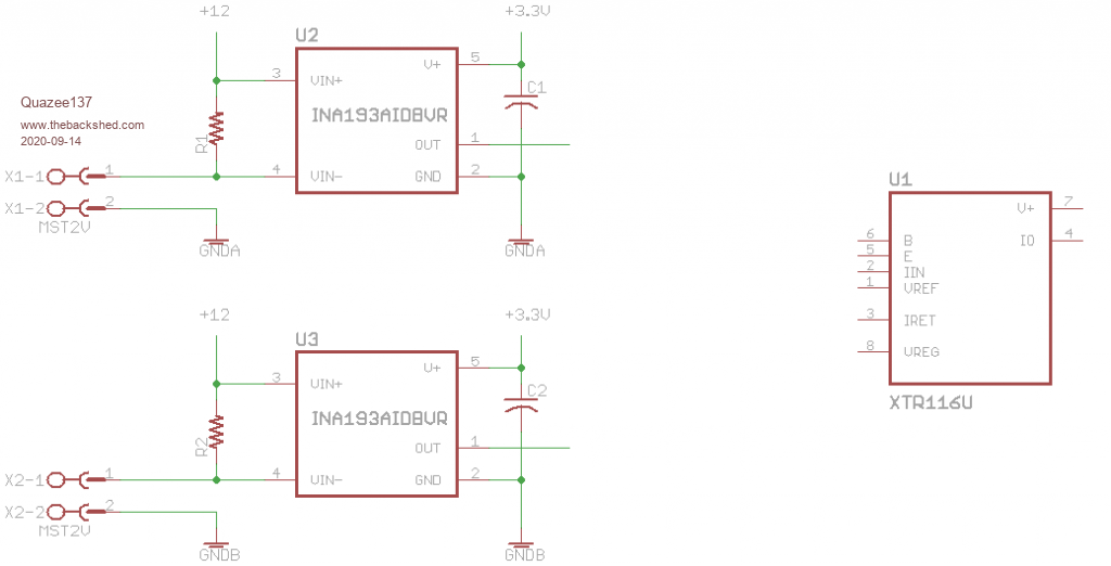 |
||||
| Volhout Guru Joined: 05/03/2018 Location: NetherlandsPosts: 5931 |
The XTR116 is not the most suitible part since it has a current input (not a voltage input), but I think we can make it work. 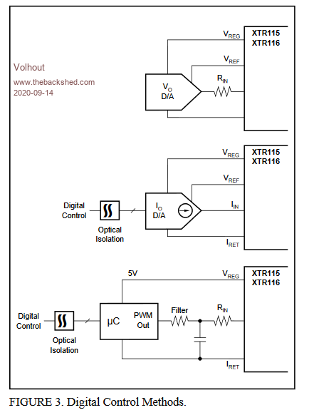 The upper circuit (opamp output = voltage -> through Rin convert to current) would give best linearity, but the lower one (PWMout -> low pass filter -> Rin) can also work if we dimension the low pass filter impedance correctly. I would need to know from you what the fastest change is that you want to support in your circuit. i.e. 10msec, or 100msec. And the resolution (i.e. 10 bit, or 8 bit or...). Then I can calculate the filter and PWM frequency for the MM2. Regards, Volhout PicomiteVGA PETSCII ROBOTS |
||||
| Quazee137 Guru Joined: 07/08/2016 Location: United StatesPosts: 603 |
I ok using the LM324 for the 4-20mA out as I have used that in other projects. I was looking at ways to shrink the board down. So I can use LM324 SOIC package and do both inputs and output as in my original analog work.Just put the MM170 in between the inputs and output to allow for better/lower cost way to do the math. Now thinking of sliders on screen to adj a percentage of each input to output. It makes calibration easier put 4mA save it then 20mA and save it getting the 16ma slope for each input. It also makes adjusting the output slope easy. It now can be used as a tester being able to read and send 4-20mA even 0-20mA. I have the LM324 on the breadboard and will play with it and the MM170 thanks to your letting me know more about how the frequency comes into play. The initial use is flow meter and Turbidity-Sensor feeding a chemical pump. Thanks again for you knowledge with the MM170 PWM. |
||||
| Volhout Guru Joined: 05/03/2018 Location: NetherlandsPosts: 5931 |
One thing to bear in mind is the isolation. In the input circuit with lm324 the pos. input is hard wired to +12v, and the neg. input varies. In the INA193 circuit the pos. Input varies, the neg. input is hard wired to ground. Both are no problem, but indicate that the current Output of your mx170 should be able to handle both. Wich means the output should not be hard wired to ground, or +12v, meaning it should be floating, isolated. The block diagrams of the xtr116 also suggest that. Your LM324 output cicuit will also require a isolation. Isolation of a PWM signal is easy, use a digital optocoupler. And the 4-20mA can power the floating circuit. As the xtr116 circuits show. Do you have good experience using the lm324 at 3.3v? Edited 2020-09-15 04:34 by Volhout PicomiteVGA PETSCII ROBOTS |
||||
| Volhout Guru Joined: 05/03/2018 Location: NetherlandsPosts: 5931 |
Hi Quazee137, I looked up a few turbidity meters, and typical response times are 2 seconds (i.e. Mettler). That means that there is not reason to go for fast response time of the system. I suggest to design for high accuracy. That also makes the choice for optocouplers easier (we don't need a fast digital one). 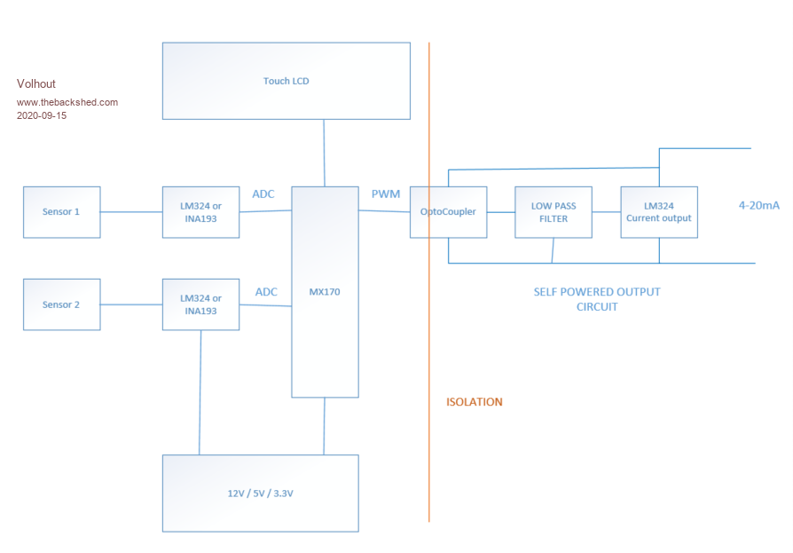 I'll look into the output circuit this evening, have to rush to work now (it's morning here). Volhout PicomiteVGA PETSCII ROBOTS |
||||
| Volhout Guru Joined: 05/03/2018 Location: NetherlandsPosts: 5931 |
Hi Quazee137, The industry standard for connecting 4-20mA sensors ties the + to 24V, and the - to a current sensing pin that connects to ground (exactly as your LM324 input circuit). See this diagram: 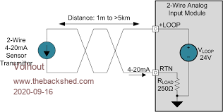 Using this knowledge for the output circuit, we can avoid the isolating opto coupler if we source current (not sink current). In simplest form this would result in following circuit: 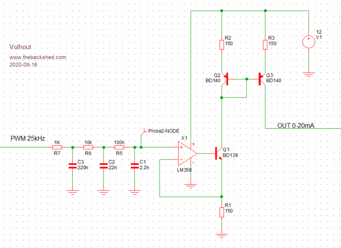 According to the MX170 documentation the PWM has 0.1% accuracy when the frequency is below 25kHz. So we pick 25kHz as PWM frequency. The low pass filter has a ripple that is 0.1% of the PWM input signal, in line with the accuracy. The step response has a delay of 1ms for 63%, and is accurate within 1% at 3ms. That is way faster than the input will vary. The current output (your LM324 circuit, only powered from 12V) feeds a current mirror (Q2/Q3), as a simple solution for sourcing current (not sinking). The transistors Q2 and Q3 should be thermally coupled for best performance. There is one caveat: heat. When powered from 12V transistor Q1 dissipates up to 120mwatt, but Q3 can dissipate 180mwatt. Using 12V you can replace Q2 and Q3 with one dual transistor, in which case the thermal coupling is perfect. For 12V Q1 can be an SOT23 2N2222, and Q2/Q3 can be a BC856S dual PNP transistor (ambient 25C, max 40C). If you use 24V, the dissipation in these parts more than doubles, and you need the transistors (or similar) as shown in the schematics to get rid of the heat. If needed a circuit can be designed that does not use the current mirror (less dissipation), but that will require another opamp. I understood you wanted a compact circuit. This is as compact as it gets... Regards, Volhout P.S. PicomiteVGA PETSCII ROBOTS |
||||
| Volhout Guru Joined: 05/03/2018 Location: NetherlandsPosts: 5931 |
 PicomiteVGA PETSCII ROBOTS |
||||
| Quazee137 Guru Joined: 07/08/2016 Location: United StatesPosts: 603 |
Sorry for being late getting back here. Been having MRI's and blood work done. � �I have to feed all three loops. All three units will be in a box mounted on a �rack and the max length of the 4-20mA loops is less than a meter. �Switching the op amps to LM358 to make it easier to do isolated inputs and �out put layouts. �I am not sure isolation is needed in this case �But still looking at the 5V to 12V DC-DC converters to power each loop. �Power in would then be 5V @250Ma in to a 3.3V reg for the MM170. �I have used the 12V to 3.3V on other MM170 projects. non-isolation would be 12V to 5V reg to 3.3V reg. � The Flow meter has adjustments to give 4 to 12mA for 0 to 1500 gpm. �and the Turbidity's 4 to 20mA will affect the remaining 4mA based on a percentage adjustment viva the touch screen. Having three displayed data. 1st the flow gpm, 2nd the turbidity's input and 3rd the pumps rate. waiting for how they want the last two referenced. The 4th will be the on screen adjustment. � �Thanks again for you work and knowledge here. Edited 2020-09-17 03:48 by Quazee137 |
||||
| Quazee137 Guru Joined: 07/08/2016 Location: United StatesPosts: 603 |
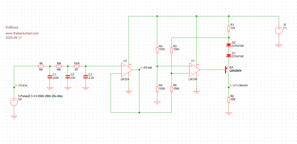
Volhout had time to breadboard the basic PWM to 4-20mA output and two 4-20mA inputs along with a bit of test code to play with. Here is what I am playing with. Things are working. Next adding resetable fuses to the three 4-20mA I/O's. Still unpacking from move in March. I have a box with a few MM170BP's V1 with 2.4" and a few of Mick's boards that should have the one more needed AIN for monitoring the output if/when driven from the pump. 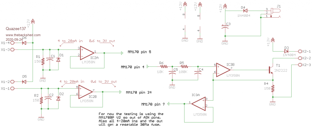 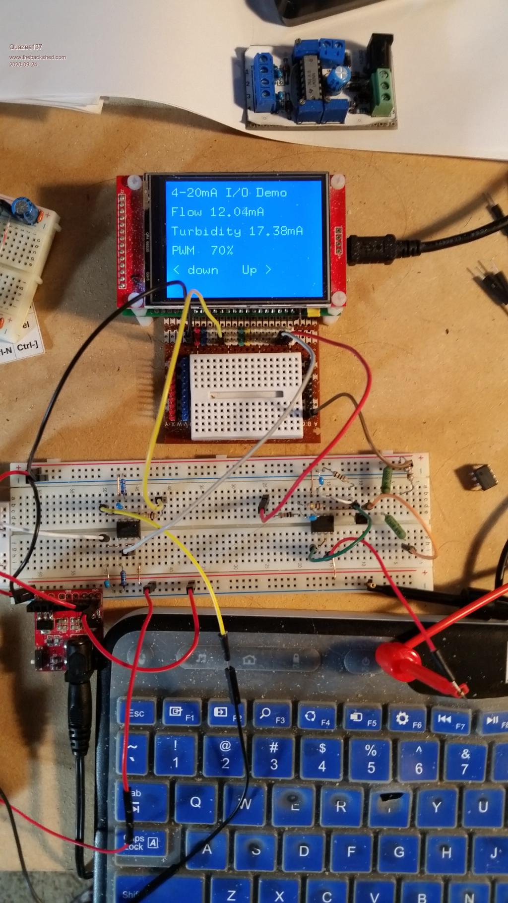 Thanks again for your help. |
||||
| Volhout Guru Joined: 05/03/2018 Location: NetherlandsPosts: 5931 |
Hi Quazee, I think resetable fuses are a good idea. But they are thermal devices. In case one of the sensors becomes a short, the LM358 get's 12V at it's input (it will survive). It's output will also become +12V (actually more like +10.5V). But it will be capable of driving substantial energy into the MX170 analog inputs. I suggest adding a 2.2k resistor in series (from LM358 out to MX170 in), so the current never exceeds 5mA. That will keep your MX170 alive. Regards, Volhout P.S> the series resistors are always nice to have, since they are great jumpers... Makes layout a lot easier. Edited 2020-09-30 22:48 by Volhout PicomiteVGA PETSCII ROBOTS |
||||
| Quazee137 Guru Joined: 07/08/2016 Location: United StatesPosts: 603 |
Volhout Thanks I have a prototype up and running. I ordered 3.3Volt zeners but they are not letting the input voltage above 2.4volts. Here is the latest work 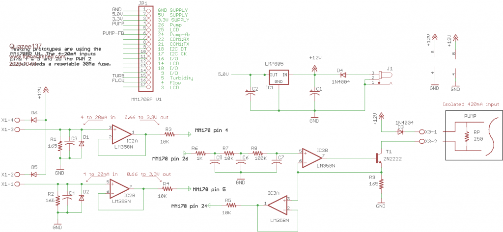 and the testing display 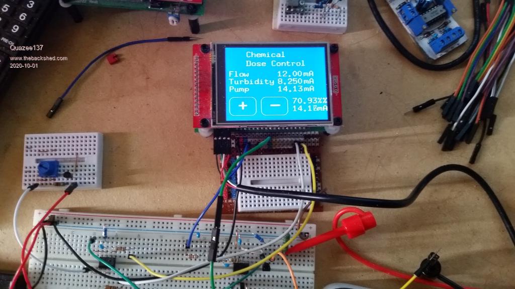 The LM324 / LM358 I have used to read 4-20mA before. Till now did not have a need to output 4-20mA. Your help has given me more ways to go using the MM170. I am using the inputs to index into a table of 2,145 data. The + - touch buttons are to shift the pump data from the table by a few percentile till we get enough data and modify the table. Now it is raw F/T to pump lookup. Having FUN Quazee137 |
||||
| Geoffg Guru Joined: 06/06/2011 Location: AustraliaPosts: 3362 |
That is what it should be all about. Geoff Geoff Graham - http://geoffg.net |
||||
| Quazee137 Guru Joined: 07/08/2016 Location: United StatesPosts: 603 |
Geoff THANKS for the MM170 it has become my main go to for my prototypes. I now get to do in weeks what took months before to do and they like the fact they get the software listing along with the hardware.  I put up a logo on the LCD while the array fills. I had used var save with my test array but the current array is 2,145. Wouldn't you know it just a tad over.  I am hand wiring three prototypes and while working I started thinking. Can the array be filled out and saved in the library like a character set? So it only needs to be filled once to save time on power up? If so then testing array(0,0) for non zero I could skip filling the array. Quazee137 |
||||
| Volhout Guru Joined: 05/03/2018 Location: NetherlandsPosts: 5931 |
Hi Quazee137, It is getting there ! I knew about the zener diodes. Especially the low voltage parts have a very weak cutoff point that starts early. What I normally do is use 1 of those zeners and a pullup resistor to create relatively hard 3.0V. And use 1N4148 diodes (these have low leakage) to clamp inputs agains that 3.0V. Resistor 500 ohm or 1k to +12V. When do you transfer from the desk to the actual industrial plant ? That is going to be FUN... Volhout b.t.w. I understand what you changed the 150 ohms to 165 ohms at the input circuit to exactly map the ADC onto 0-20mA. I suggest otherwise. I always keep some headroom, so you can detect faults. If the current exceeds 20mA (bad isolation or bad sensor) your ADC will measure 20mA. With 150 ohms you will be able to detect the fault since you would measure 22mA, and see that it is out of range. Similar, if you measure 0mA, there is a wire break. Edited 2020-10-03 01:39 by Volhout PicomiteVGA PETSCII ROBOTS |
||||
| Quazee137 Guru Joined: 07/08/2016 Location: United StatesPosts: 603 |
I put 5.1V zeners in for now it should keep the input from going to 12Volts The 165 ohms will be ok as they are setting the input flow input max is 12mA and the turbidity is set to 3.9 to 19.5 for reasons they did not go into. A few other changes are a bridge rectifier 12 and 5 volt regulators. They have 24VAC and a 15VDC so which ever the hook up to should do. At the old house I had all kinds of equipment I could use for testing. Here I wired up a few LM317 making 0 to 25mA test jigs. For the output I had to dig out my old multimeters that have 000.000mA display ability where as my newer ones only have 00.0 on the 20mA setting. While the field testing is being done using the MM170BP's. I will work on a PCB with all the parts and may goto a small I2C Display and a three key touch pad. I fit an early project with the MM170 and four opto isolators and relay into a small din-rail case. This is not much more hardware wise other than the 2.8"display. With the extra pins I can add alarms or auxiliary controls even use the ESP's on com ports 1 or 2 for WiFi to browser for phone/computer use. Also getting around to using the SD-card for data logging. So much FUN stuff that can be done with the MITES and MMBasic. Thanks Quazee137 |
||||
| Volhout Guru Joined: 05/03/2018 Location: NetherlandsPosts: 5931 |
Hi Quazee137, What a nice project .... very very much FUN I can tell. If you are making a PCB for final (not using a backpack), and plan to have SD card for logging, you may want to design around a 64 pin MM+. It has full SD support. And cost wise would not be a showstopper. Soldering the 64 pin is nut much more difficult than the 44 pin MM2 part. For the rest it is the same MMBasic core .... Volhout P.S. I understand you can use the MX170 with SD card with matherp's libraries, but if in few years someone has to dive into this, or replace the SD card, no-one will remember that you need to pre-image the card with a log file that must the be the right size for the maximum amount of data you will collect (look into the future..??), otherwise it won't work. That is my main problem with using this MX170 library. In 2 years time I will have forgotten what limitations exist with this library. P.P.S. Do you have a link to that DIN rail case ? Edited 2020-10-05 21:31 by Volhout PicomiteVGA PETSCII ROBOTS |
||||
| Page 1 of 2 |
|||||
| The Back Shed's forum code is written, and hosted, in Australia. | © JAQ Software 2026 |
