
|
|
Forum Index : Microcontroller and PC projects : Armmite F4: programming the firmware
| Author | Message | ||||
| matherp Guru Joined: 11/12/2012 Location: United KingdomPosts: 11513 |
The pins are wired to the LEDs on the PCB. Remove the LEDs or their pullup resistors and then the pins will behave normally. By default all pins are set as "analogue" This is the recommended state for unused pins on all STM32 chips to minimise power usage. It is different from setting them as analogue inputs. The voltage you are seeing is the LED voltage and they are dimly lit as there is a very small current flowing |
||||
| Cremo Newbie Joined: 21/07/2015 Location: ItalyPosts: 36 |
Hi Gerry, I am very interested in the 800*480 IPS display. I would like to know the status of your work about using it with MM+ at 8 bits. Thank you. Pietro |
||||
| ceptimus Senior Member Joined: 05/07/2019 Location: United KingdomPosts: 130 |
I've have this discovery board sitting idle: it has the -VGT6 version of the chip rather than the -VET6 one - as far as I can see it's the same chip except that it has 1024kb of on-chip Flash rather than 512kb. 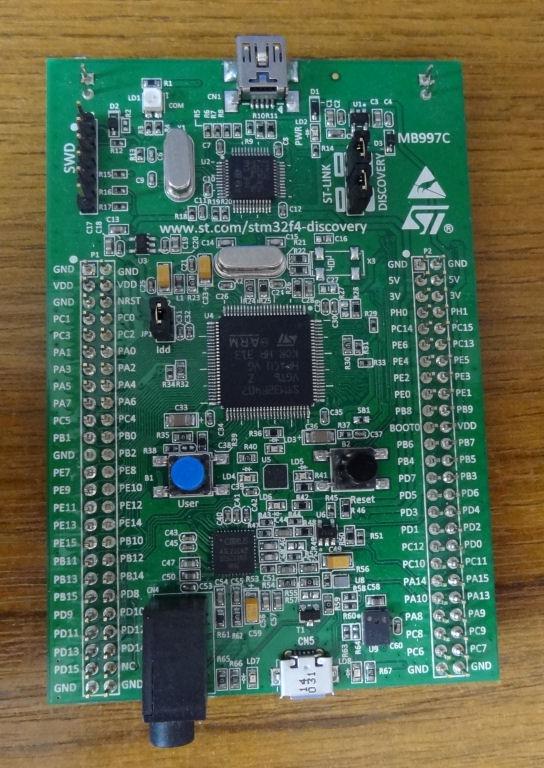 Any chance this would work with Armmite F4? |
||||
| matherp Guru Joined: 11/12/2012 Location: United KingdomPosts: 11513 |
Bug fixes for LOC() and SEEK() BLIT READ, BLIT WRITE, BLIT CLOSE implemented as per MM+ manual ArmmiteF4.zip |
||||
Chopperp Guru Joined: 03/01/2018 Location: AustraliaPosts: 1126 |
Hi Peter, Can this version be updated sometime please if possible? I do have one board using it. Thanks Brian ChopperP |
||||
| matherp Guru Joined: 11/12/2012 Location: United KingdomPosts: 11513 |
PM me with your email address. I don't want to post variants as it will just confuse. |
||||
| Chopperp Guru Joined: 03/01/2018 Location: AustraliaPosts: 1126 |
Done ChopperP |
||||
| matherp Guru Joined: 11/12/2012 Location: United KingdomPosts: 11513 |
Another go at the LOC/SEEK file issue ArmmiteF4.zip |
||||
| erbp Senior Member Joined: 03/05/2016 Location: AustraliaPosts: 195 |
Hi Peter, I have a new problem that has shown up in the latest (2019-09-25_023322_ArmmiteF4.zip) version of the firmware. When I try to load a program from SDCard I get the following error: [1906] End DefineFon Error: Invalid hex word > Here is the code as in the file on the SDCard: DefineFont #8 60200604 44000000 00A04040 A0AEAE00 82406C6C EACC2048 00004460 84204424 E4A48044 00E404A0 00800400 040000E0 00480240 4CE0AAEA 48C24044 C062C2E0 E820E2AA EA68E0E2 8048E2E0 EAE0EAEA 0404C0E2 80040400 0E208424 2484000E 4040E280 4A60E84A CACAA0EA 608868C0 E8C0AACA E8E8E0E8 60EA6880 E4A0EAAA 2A22E044 A0CAAA40 AEE08888 EEAEA0EA 40AA4AA0 4A80C8CA ECCA60AE C04268A0 AA4044E4 A4AA60AA A0EEAA40 AAA04AAA 48E24044 E088E8E0 E2004208 004AE022 F0000000 0C000084 AA8CE06A 608806C0 0660AA26 E42460AC 24AE0640 40A0CA88 22204044 A0CC8AA4 0EE044C4 AA0CA0EE 40AA04A0 06C8AA0C 880662AA C0C60680 0A60444E AE0A60AA E0AE0A40 0AA0440A 6C0E24A6 608464E0 C4400444 006CC024 E0EEEE00 End DefineFont Line [1906] is the final record in the file. I notice that the error message does not include the final "t" in DefineFont, but the file shows the "t" is there. I don't know if this is significant or not. If I reload the previous version of F4 firmware (2019-09-23), I can load and run the same file from the SDCard, so whatever is triggering this error was only introduced in the most recent firmware version.  Regards, Phil. |
||||
| matherp Guru Joined: 11/12/2012 Location: United KingdomPosts: 11513 |
Thanks for the report. Eof is triggering a character early. For the moment the workround is to add a blank line after the End DefineFont Fixed firmware attached ArmmiteF4.zip Edited 2019-09-29 01:56 by matherp |
||||
| erbp Senior Member Joined: 03/05/2016 Location: AustraliaPosts: 195 |
Hi Peter, Confirming that the latest firmware (2019-09-29) fixes the problem. Many Thanks, Phil. |
||||
| ceptimus Senior Member Joined: 05/07/2019 Location: United KingdomPosts: 130 |
I ordered two of the same board from Banggood and they arrived today, but as you can see, they messed up and sent me two different boards. 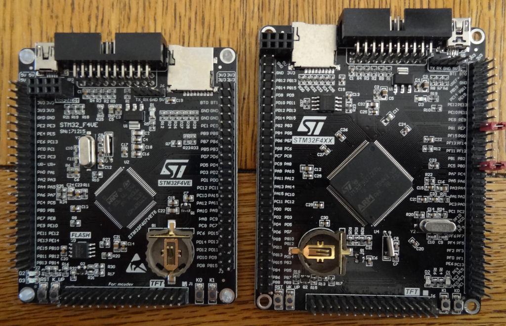 The header pins were badly bent in shipping, but I straightened most of them out before taking the photo. The larger board also has pads for a chip (RAM ?) to be soldered on the back. 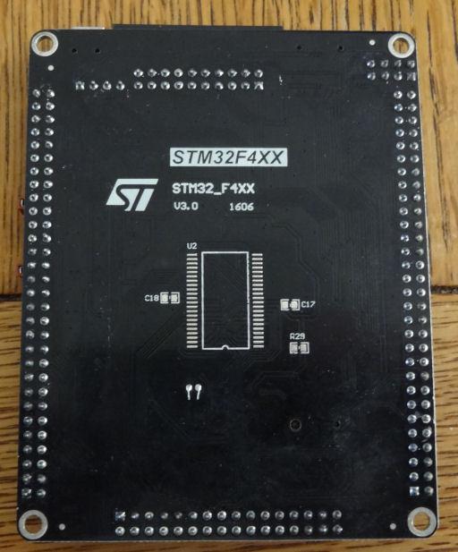 I also ordered a couple of the displays to go with them (they're both the same). �I was looking for some displays with female connectors to dock straight onto the STM board, but the cheap ones on Banggood and Ebay all seem to come with male headers, so I'll need a female-to-female ribbon cable or similar to connect them. �Maybe an old IDE hard disk connecting ribbon would work? I shall experiment with the boards and let you know if I can get either/neither/both of them to run Peter's firmware. Edit to add: Both boards accepted the firmware. �Thanks to Peter for his very clear instructions in the O.P. of this thread. �Both boards report the same memory (144K Flash, 114K RAM). The larger board has BT1 and BT0 swapped side-to-side and "moved up" one pin (there are only two 3.3V pins above them not four). Also, although there is a GND adjacent to BT0, the pin on the side adjacent to BT1 is now VREF+, so you have to use a jumper lead rather than a link to connect it to GND for the first stage of flashing. I've equipped them both with CR 1220 batteries and set the time/date. �Next I'll add the displays. I'm thinking of designing and 3D-printing some kind of case/mount to hold the smaller (standard) board and standard small display. �I'll upload the design here once I've tested it. . Edited 2019-10-02 02:24 by ceptimus |
||||
| matherp Guru Joined: 11/12/2012 Location: United KingdomPosts: 11513 |
The smaller PCB is the ciorrect version and should work fine. However for the bigger..... The MMbasic firmware uses physical pin numbers to protect reserved pins from normal MMbasic operations like initialising the pins state on boot. I'm pretty sure the display won't work on the bigger screen and you may find things like SDcard don't work either. Pin mappings will be all over the place and even using SETPIN PB6 etc won't work as that also maps through the pin number table. Edited 2019-10-02 04:05 by matherp |
||||
| ceptimus Senior Member Joined: 05/07/2019 Location: United KingdomPosts: 130 |
Thanks. �My displays are both ILI9341 3.2-inch 320x240 with 34 pins and a (full size) SD card interface. This one:   � �I figured out the the connections and hooked it up to the smaller STM32 board with a bunch of 10cm female-to-female jumper wires. Calibrated the touch, and the GUI test delivers 1171 circles per second. The backlight command works but higher numbers give a dimmer display - is that the same as with the correct pin-out display module that plugs straight on? I'll look into the larger board and see if I can figure out how the pins are arranged. �I suppose I could complain to BangGood and see if they'll send me another small board for free to correct their mistake, but I won't be sending the bigger one back if I have to pay the shipping - that would cost me more than just buying another small board outright! . Edited 2019-10-02 08:49 by ceptimus |
||||
| Volhout Guru Joined: 05/03/2018 Location: NetherlandsPosts: 5931 |
For one reason or another, the search function on the forum does not work for me at the moment. That is why I need your help. Is there anyone that can point me to the documentation for the ARMmiteF4 (STM32F407VET6 board). I am looking for the pin functions. I am guessing that pin 15 is an ADC channel (10..?) pin 97 and 98 are free for digital IO pin 31 is PWM1 ?? pin 51 is chip select for touch pin 34 is interrupt for touch Is this correct ? Thanks, Volhout I am porting my Backpack Tracker to ARMmiteF4. It seems to run double as fast. Edited 2019-10-02 20:32 by Volhout PicomiteVGA PETSCII ROBOTS |
||||
| morgs67 Regular Member Joined: 10/07/2019 Location: AustraliaPosts: 78 |
Hi Volhout, From page 1 of this topic, http://www.thebackshed.com/forum/ViewTopic.php?TID=11334#134494 cheers Tony |
||||
| Volhout Guru Joined: 05/03/2018 Location: NetherlandsPosts: 5931 |
Thanks Tony, I used this list, but thought I could be using the wrong list since I had problem assigning an interrupt to touch. In MX170: � �'PIC32MX170 initialisation � �'OPTION LCDPANEL ILI9341, L, 2, 23, 6 � �'OPTION TOUCH 7, 15 and in the basic program you assign an interrupt by �' enable touch �SetPin 15, INTL, Touch_Int In The ARMmiteF4 the options are � �'STM32F407VET6 initialisation � �'OPTION LCDPANEL ILI9341_16, LANDSCAPE � �'TOUCH PB12, PC5 And in the basic program (at least that is what I thought) �' enable touch �SetPin 34, INTL, Touch_Int Also tried using "PC5" in stead of "34" but I consistently get following response on ARMmiteF4: [123] SetPin 34, INTL, Touch_Int Error: Pin PC5 is reserved on startup Any idea ? Edited 2019-10-02 23:10 by Volhout PicomiteVGA PETSCII ROBOTS |
||||
| Chopperp Guru Joined: 03/01/2018 Location: AustraliaPosts: 1126 |
The F4 uses the same GUI commands as the MM+ as I recently found out but with all pins already configured. Uses GUI touchdown etc. This gives the touch(x) & touch(y) coorrdinates. Best read the MM+ manual on the GUI. I had to.  Hope this helps. ChopperP |
||||
| JohnS Guru Joined: 18/11/2011 Location: United KingdomPosts: 4335 |
In case it helps, you can improvise using searches in google like: site:http://www.thebackshed.com/forum/ STM32F407VET6 (I understand Glenn is busy improving the site as fast as he can.) John |
||||
| lizby Guru Joined: 17/05/2016 Location: United StatesPosts: 3784 |
Using the forum search for that exact topic, "STM32F407VET6", has worked for me several times lately, and worked just now (but I don't know if anything is omitted). (I do love the google "site:" option for searching--it's good occasionally to put out notice that it's there for folks who may be unaware of it.) PicoMite, Armmite F4, SensorKits, MMBasic Hardware, Games, etc. on FOTS |
||||
| The Back Shed's forum code is written, and hosted, in Australia. | © JAQ Software 2026 |
