
|
|
Forum Index : Microcontroller and PC projects : Armmite F4: programming the firmware
| Author | Message | ||||
| lizby Guru Joined: 17/05/2016 Location: United StatesPosts: 3348 |
PM sent. |
||||
| lizby Guru Joined: 17/05/2016 Location: United StatesPosts: 3348 |
I can't say that went well. I managed to lift a pad on the 1963_PWM link on the 4.3" panel. With the 7" panel, with the adapter jumper on BL, the panel started off very dim. It increased in brightness up to BACKLIGHT 70, but still dimmer than it had been. BACKLIGHT 80 made it dimmer still, and BACKLIGHT 99 made it almost invisible. That was with the adapter 5V disconnected. There was little difference when I plugged adapter 5V pin into 3V3 or 5V on the F4. Switch the adapter jumper to 5V and the adapter 5V pin to 3V3 and all is nice and bright as originally. The 4.3" panel with no jumpers on the panel's backlight settings works fine in this same configuration (with OPTION LCDPANEL changed, of course). GUI CALIBRATE still doesn't work on the 7" panel, but does on the 4.3". GUI CALIBRATE had worked on the H7--I'll try that again. It's certainly possible that I damaged the panel. PicoMite, Armmite F4, SensorKits, MMBasic Hardware, Games, etc. on fruitoftheshed |
||||
| matherp Guru Joined: 11/12/2012 Location: United KingdomPosts: 10181 |
As with the MM+, all my ports expect SSD19623 displays to have the backlight jumper in the 1963_PWM position. The backlight command in the MM firmware sends commands to the SSD which itself runs a PWM output which drives the backlight circuitry. The BL pin from the STM32F407 is a 1KHz PWM which was configured specifically for the ILI9341 display. The output is inverted for the SSD1963 wiring if the SSD is left in the LED_A configuration so BACKLIGHT 0 will give the brightest output for a SSD. The LED_A pin is a logic level on the SSD displays - it doesn't power the backlight. The power comes either from the 3.3V pin (4.3" and 5") or the 5V pin which is only connected on the 7" |
||||
disco4now Guru Joined: 18/12/2014 Location: AustraliaPosts: 1000 |
Hi Peter, I am trying to access the pins on the LCD header, but they all seem to be invalid when trying to access with SETPIN etc. e.g. setpin pd14,dout Error: Pin 61 is invalid > The pin definitions previously posted seem to support this as they show as unused. I was starting to play with writing a BASIC LCD DRIVER but have fallen at the first hurdle. Would it be possible to make the following pins available, 36,61,62,81,82,38-46,55-57,85,86,60,88 Regards Gerry PS I did OPTION LCDPANEL DISABLE, but this did not help. Edited 2019-08-12 21:42 by disco4now Latest F4 Latest H7 FotS |
||||
| matherp Guru Joined: 11/12/2012 Location: United KingdomPosts: 10181 |
The LCD pins are always unavailable to MMBasic. They are configured when you enable an LCD - ILI9341_16 or SSD1963_n_16. The Armmite F4 uses the FSMC port on the processor which maps the display as an area of memory. |
||||
| disco4now Guru Joined: 18/12/2014 Location: AustraliaPosts: 1000 |
OK,understand. I was getting excited about this 800*480 IPS display as the other IPS one is very clear. $AU22 here I made an adaptor and plugged into the F4. Touch calibrated (blind) and seem to work, and BACKLIGHT 0/100 turned the backlight on off. I will try to get it to go as 8bit on an MM+ Gerry Latest F4 Latest H7 FotS |
||||
| Decoy Senior Member Joined: 02/08/2019 Location: DenmarkPosts: 109 |
I just tried this, works great. Thanks for the awesome instruction!! I am just sad that I cannot get VGA output (or composite - even B&W would be great) output, or keyboard input. Edited 2019-08-13 03:25 by Decoy |
||||
| lizby Guru Joined: 17/05/2016 Location: United StatesPosts: 3348 |
I'm baffled by a problem on a PCB I designed for the F4. Among other things it is set up to read 8 DS18B20s on pins 1,4,5,7,15,16,17,18. I tested each of these pins successfully with a single DS18B20 3-pin module with built-in 4K7 resistor. I soldered up my board with a bussed 4K7 resistor array. All the temperatures read fine, but I get "SD card not present" if I issue the FILES command. I tracked it down, and if I don't connect pin 7 (PC13), the other temperatures work and the SD card also works. I went back and checked with the single DS18B20 module. Each TEMPR command works (pins 1,4,5,7,15,16,17,18), and FILES works after each one. I wondered if it might be a power draw, but it sits between 65 and 69 mA. I can find another pin to use besides 7, but I wonder what the reason is for this behavior? (I see that pin 7 has for "Function" "Digital, 3mA total for PC13-PC15", but I'm not sure how this would be related.) 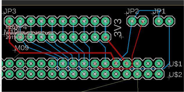 Edited 2019-08-13 07:46 by lizby PicoMite, Armmite F4, SensorKits, MMBasic Hardware, Games, etc. on fruitoftheshed |
||||
| matherp Guru Joined: 11/12/2012 Location: United KingdomPosts: 10181 |
I suspect some sort of crosstalk internal to the chip between PC13 and PC12 (SD-CLK). I had huge problems getting the SDcard to work reliably. Eventually I had to use 1-bit SDIO rather than the faster 4-bit and slow the SDIO clock as I was seeing this sort of problem. Could be an issue with the ST driver or, as I suspect, some sort of hardware crosstalk. |
||||
| matherp Guru Joined: 11/12/2012 Location: United KingdomPosts: 10181 |
Minor update to fix bug in ARC command ArmmiteF4.zip |
||||
| SWA-Guy Newbie Joined: 01/02/2019 Location: GermanyPosts: 24 |
Hi guys, I can confirm lizbys problem with the 1-wire communication on PIN PC13. I use a DHT22 and sometimes I have no connection to the sd-card. If I disconnect the DHT22 the communcation to the sd-card directly works. Greeting from Germany Juergen |
||||
| lizby Guru Joined: 17/05/2016 Location: United StatesPosts: 3348 |
Thanks for the confirmation (and welcome to the forum) and thanks for the explanation (even if the root remains a mystery). Mysteries do abound--I'm glad MMBasic has relatively few of them, thanks to the efforts of Peter and Geoff. Edited 2019-08-14 02:27 by lizby PicoMite, Armmite F4, SensorKits, MMBasic Hardware, Games, etc. on fruitoftheshed |
||||
| lizby Guru Joined: 17/05/2016 Location: United StatesPosts: 3348 |
When I hook LEDs up to pins 92,93,89,91,87,84,77,67, two--89 and 77 (PB3 and PA15)-- are on weakly. They respond normally (with brightness corresponding to the other pins) to, e.g., PIN(89)=1 and PIN(89)=0. What am I seeing here with these pins? After setting them low, "NEW" brings them back on weakly. Are all of these pins OK to use digitally? Is there a way to have 89 and 77 not doing whatever they are doing upon power-up? 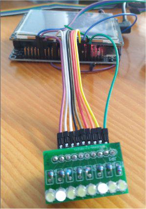 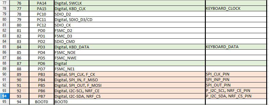 Edited 2019-08-25 01:05 by lizby PicoMite, Armmite F4, SensorKits, MMBasic Hardware, Games, etc. on fruitoftheshed |
||||
| matherp Guru Joined: 11/12/2012 Location: United KingdomPosts: 10181 |
PB3 and PA15 have 10K pullups on the PCB. Remove R1 and R3 if you don't want them |
||||
| lizby Guru Joined: 17/05/2016 Location: United StatesPosts: 3348 |
Thanks. That did the trick. option base 1: dim integer i,p(8)=(92,93,89,91,87,84,77,67) for i=1 to 8: setpin p(i),dout: pin(p(i))=1: pause 500: next i for i=1 to 8: pin(p(i))=0: pause 500: next i Edited 2019-08-26 01:03 by lizby PicoMite, Armmite F4, SensorKits, MMBasic Hardware, Games, etc. on fruitoftheshed |
||||
Chopperp Guru Joined: 03/01/2018 Location: AustraliaPosts: 1094 |
Hi matherp I also have problems with one of my F4 boards with the USB OK in programming but not for normal the normal connection. (Device unrecognised) I ended up trying the above version first & it DID work for me. Great!!! I then tried the first version but that didn't work. (2019-05-25_191158_ArmmiteF4.zip ) Reloading the second version brought it back to life. I don't suppose that there has been any updates on the later version has there?  I uploaded a small program & it looks like the board will be usable for this purpose so all is not lost if no updates are available. Brian ChopperP |
||||
TassyJim Guru Joined: 07/08/2011 Location: AustraliaPosts: 6266 |
My F4 boards arrived and I have had a chance to play today. I had to upgrade my STMCube software before it was recognised but after that, it was plane sailing thanks to your clear instructions. I used the 13/8/19 firmware. File system seems to work well using MMEdit file manager. One oddity. The first time I plugged the boards in after loading the firmware, the device was not recognised but unplugging and reinserting and all was well. This happened for both boards. Jim Edited 2019-08-29 16:32 by TassyJim VK7JH MMedit |
||||
| Chopperp Guru Joined: 03/01/2018 Location: AustraliaPosts: 1094 |
It's when the boards aren't recognised the second time you really start to worry. Have fun playing. Be careful with the unsupported end of the Panel. They crack easily & destroy the F4 board. I just uploaded another small program on my troublesome board mentioned in my previous post. All OK. COM3 OK on Tx & COM4 OK on GPS Rx. Did some time checks overnight & today on both the RTC (not powered) & also running. Also OK. ChopperP |
||||
| CaptainBoing Guru Joined: 07/09/2016 Location: United KingdomPosts: 2170 |
This happens with both my boards all the time and has been reported by others - it seems to be a toggle... first time ok, then not, then next ok... I seem to remember it was something to do with the little "break-off" board at the top (can't remember its name) and its USB device. If you remove the jumpers (J6?) and go straight onto the console pins with your own USB adapter is works fine. hth |
||||
| lizby Guru Joined: 17/05/2016 Location: United StatesPosts: 3348 |
Upon power-up, pins 31 and 32 (PA6--Digital, Analog, ADC1, ADC_CHANNEL_6, PWM1A, TIM3_CH1, LED-D2--and PA7--Digital, Analog, ADC1, ADC_CHANNEL_7, PWM1B, TIM3_CH2, LED-D3) have voltages around 1.78. The LEDs they're associated with, D2 and D3 are dimly lit. If I do SETPIN 31,DOUT: SETPIN 32,DOUT then the LEDs show inverted values: PIN(31)=0: PIN(32)=0 turns them on and PIN(31)=1: PIN(32)=1 turns them off. I'd really like to use these a digital inputs. If I do SETPIN 31,DIN: SETPIN 32,DIN the voltage are back at 1.78. Is there a way I can deal with this so that I can easily enough use them as digital inputs? Edited 2019-08-30 03:33 by lizby PicoMite, Armmite F4, SensorKits, MMBasic Hardware, Games, etc. on fruitoftheshed |
||||
| The Back Shed's forum code is written, and hosted, in Australia. | © JAQ Software 2025 |
