
|
|
Forum Index : Electronics : Bryan's Inverter build
| Author | Message | ||||
Bryan1 Guru Joined: 22/02/2006 Location: AustraliaPosts: 2138 |
Went upto Rogers after work today and what a learning experience it was helping solder on the wire to the board  So VS1 & VS2 now have 50sqmm wire on each pad and had enough length off the toroid wire for the battery connect so 65sqmm 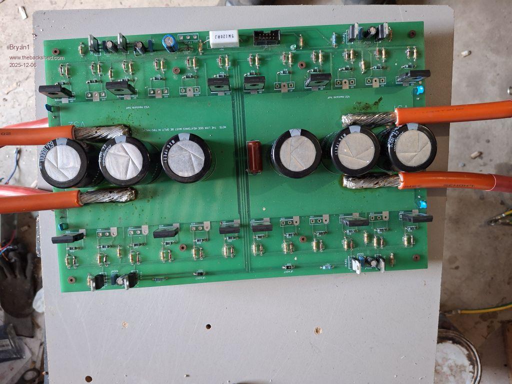 So the 50sqmm wire for VS1 & Vs2 will be bent down to attach to each choke, now we did measure the inductance using Rogers meter and both chokes came in a 24uH within a point of each other so good to see they are matched. Now I did mention about charging the caps before turn on and suggested the battery connect would do it and got told well the inrush of current to charge the caps will show the fireworks  and a bleed resistor is required to limit the current on the positive rail to charge the caps. So lesson learned and that is one thing I never read in all the reading on this inverter. and a bleed resistor is required to limit the current on the positive rail to charge the caps. So lesson learned and that is one thing I never read in all the reading on this inverter.So one step closer. Regards Bryan |
||||
| Bryan1 Guru Joined: 22/02/2006 Location: AustraliaPosts: 2138 |
Well in my gear I did find 3 off 40 watt 200ohm resistors that all measure within 3 ohms so I could use one of them to slowly charge the caps before the first turn on. Now for members that have build this inverter how did you guy's go about charging the caps Regards Bryan |
||||
| Bryan1 Guru Joined: 22/02/2006 Location: AustraliaPosts: 2138 |
G'Day Guy's, Well finally had an afternoon to work on this inverter after work today and after installing the fan got the box in it's new home and got the Anderson Connector all done 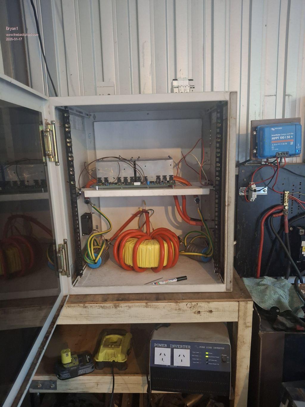 So getting closer... Cheers Bryan |
||||
| rogerdw Guru Joined: 22/10/2019 Location: AustraliaPosts: 955 |
That's looking good Bryan, definitely getting closer. Cheers, Roger |
||||
| Bryan1 Guru Joined: 22/02/2006 Location: AustraliaPosts: 2138 |
Well got a bit more done today and it was taking 3 steps forward and one step back Found some old terminal block so cut it in half and screwed them onto the perspex plate only to find one of the closures was buggered So that idea is going to be scrapped and I'll machine up some new terminal blocks.Then got onto the finish soldering the brain board and soldered up the lcd board where silly me didn't see the front holes on the nano aren't used and lost a couple of pads desoldering. So went and grabbed another Nano and soldered everything in properly and found out the hard way where last time I had to use my good laptop to program the nanos last time as both the linux and my shed computer wouldn't program the Nano. I will get more done thru the week and hopefully next weekend it will be finished then the fun can start and see if it will power my mig welder. |
||||
| Bryan1 Guru Joined: 22/02/2006 Location: AustraliaPosts: 2138 |
Well as it cooled down had a day in the shed and this inverter is 95% done 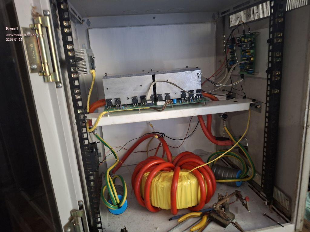 Now call this timing from Poida or what as I do still need to wire up VFB and didn't even think about the stepdown transformer so I am glad this came out Now a few years I did get a stepdown transformer and it's sat on my computer desk in the house for years but should fit the bill 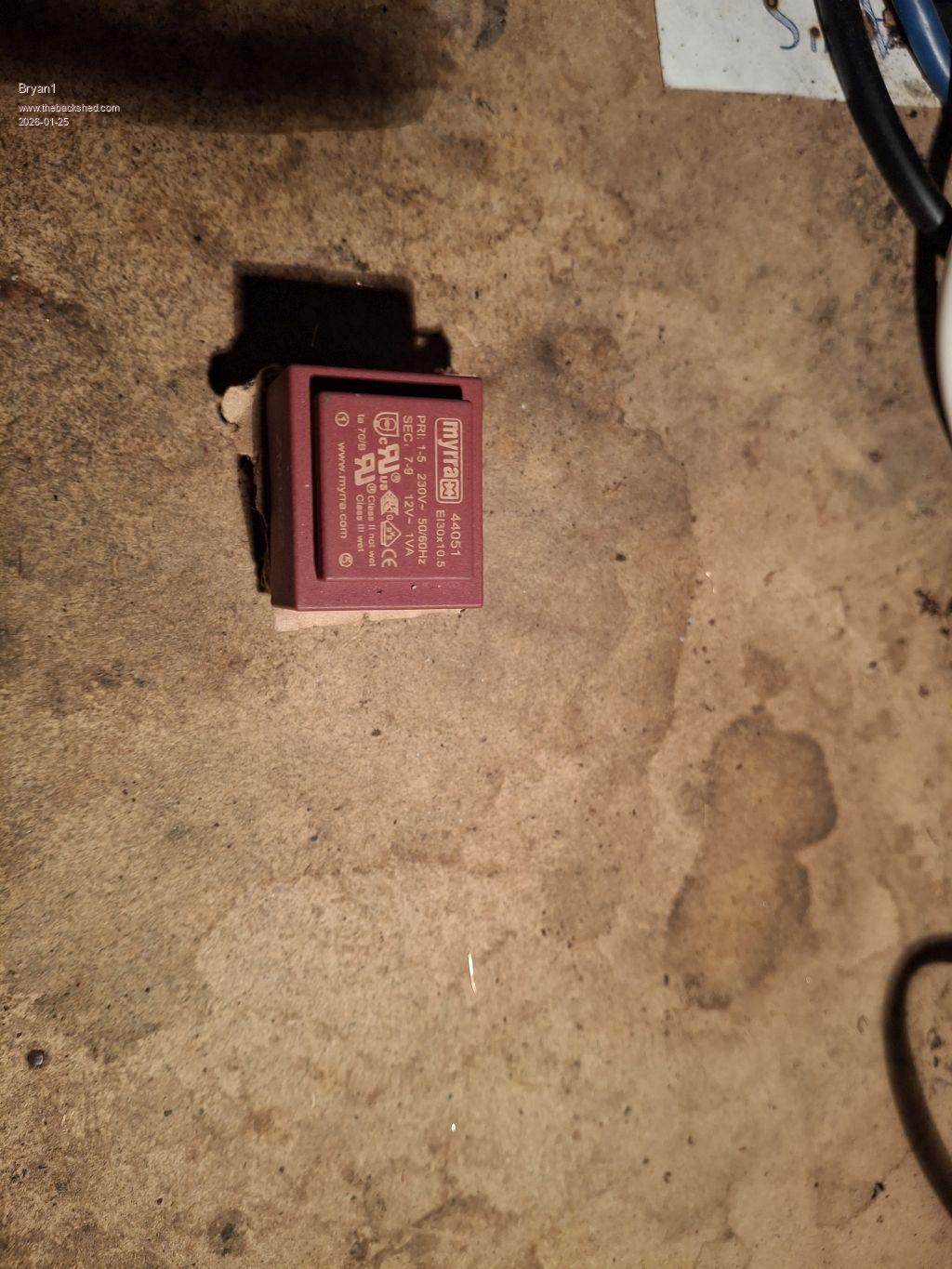 Found some 3mm long threaded bolts and the nuts to suit but the thread isn't 3mm more likely a BA size. so with some 6mm perspex mounted to the din rail the lcd can be mounted. So just got the AC side to sort out, VFB and the on/off switch. Also still got to tension all the bolts and insulate them with that yellow tape. ON talking with Roger about charging the caps before turn on I do have 3 40 watt 200 ohm resistors 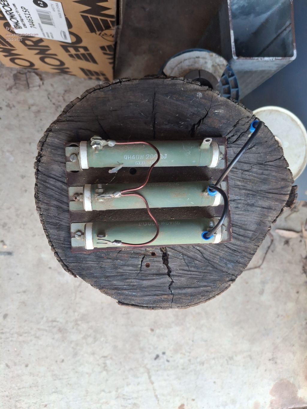 So by wiring them in parallel got the ohm's down to around 60 off memory which will limit the inrush current to 300mA which should suit the task I did solder the rear battery pads with some wires to bring the battery voltage for the 15 DC stepdown board so I'm thing take a rail off that to charge the caps from my shed battery and when the battery voltage is reached connect the anderson connector and turn the inverter on. |
||||
| Bryan1 Guru Joined: 22/02/2006 Location: AustraliaPosts: 2138 |
Well got a couple of hours before it heats up today and got the datasheet for that myrra transformer Now off memory the grey cells are starting to return and on the AC output shouldn't 5uf be put across the output ? I do need to make up a pcb for the transformer which can also mount the AC output via those 4mm pcb ones I have here and that 5uf cap once I find one can go on the board too. 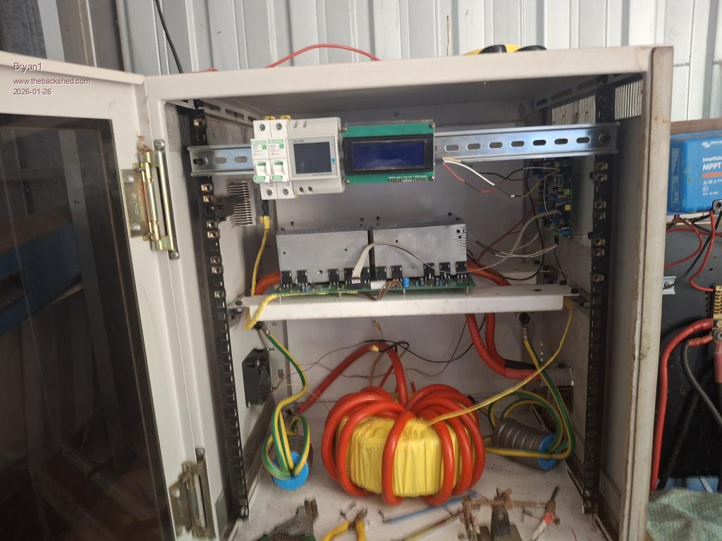 So it got to 47C in my shed today and all I'm missing is that 5uf capacitor now if I may ask Roger as he has helped in this build to come over and have a look at my work so we can start this inverter and just let it go for many years. The only thing I need to change to goto 48 volts is the 15 volt step down converter to suit 48 volts but at 5K for a 24 volt 1,000AH hour battery one will do for now. Now this inverter will power my shearing shed so I can finally get over the line to distilling and making a product every likes Edited 2026-01-26 17:24 by Bryan1 |
||||
| Bryan1 Guru Joined: 22/02/2006 Location: AustraliaPosts: 2138 |
Well working on the inverter last night I did notice I had the Anderson connector upside down and I am glad I found it, anyway turning it around and clamping it back didn't take long. So got onto finishing the AC board and got mounted then got onto the AC wires and for the wire just stripped a couple of metres of 3 phase 32 amp wire I had here and with one lead from the toroid it went thru the hole of this energy meter then back to the AC board. A few little jobs left like make the wires for the VFB connection and fix the temp sensor wire on the toroid as it did pull out when I was tensioning the connections. Also got the earth to sort out. 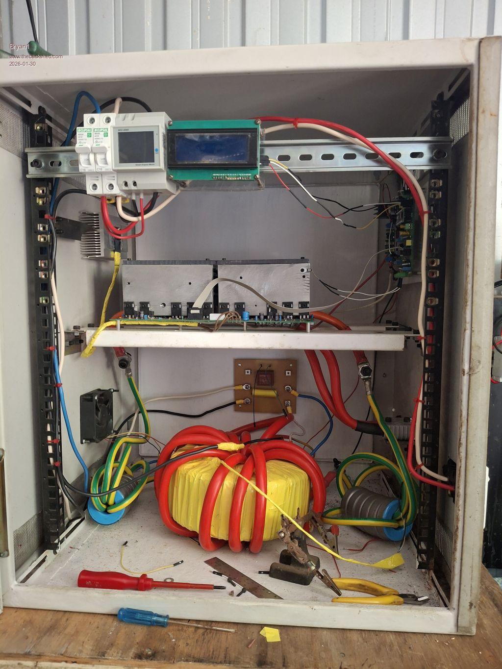 So tomorrow will be the big day to see if my hard work has paid off Now don't know why Aussie post has become snail mail as had one Ali package sitting at Adelaide airport since Last Saturday and that SSD 128gig HD coming from Brisbane from Umart is still there after 4 days. Cheers Bryan Edited 2026-01-30 15:24 by Bryan1 |
||||
| Godoh Guru Joined: 26/09/2020 Location: AustraliaPosts: 675 |
Good luck with the switch on and testing. This has been a long project I hope it works first time and no smoke gets out Pete |
||||
| Bryan1 Guru Joined: 22/02/2006 Location: AustraliaPosts: 2138 |
Well got everything finished this morning and ready to charge the caps which is where the best and safest way is the only way to go.I do have a couple of power supplies here and my old 30 volt 3 amp power supply would be the go so the voltage can be raised slowly then when at battery voltage connect the Anderson connector and turn it on. Also I have that programmable 30 volt 10 amp supply where I can preset the current for a slow charge up. Now as this inverter has taken that long to build I will wait for a reply on the best way to get this job done. Regards Bryan |
||||
| KeepIS Guru Joined: 13/10/2014 Location: AustraliaPosts: 2196 |
I'm not sure quite what you mean? So i'll suggest a few general things. Charging the Caps, which are the Caps across the FETs via the inverter DC input. You only need that pre-charge resistor network you made (around 60 ohm from memory) in series with the DC supply, the max current for a 30V supply would be around 500mA. With no inverter load this will charge the caps to 30V in a few seconds. The bang comes if you have too much capacitance across the FETSs for the first power up test. Even 2000uf could take out a FET if something failed close to 30V of cap charge, it depends on a number of unknown, to me, construction variables, so I always assume the weakest link, worst-case situation. Option 1: Only place around 470uF across the FETS for the initial low power tests via the pre-charge resistor, and monitor inverter AC sine wave (no load) If you can't disconnect the existing Caps across the FETS. Use the variable supply (current limit set to around 300mA) and very slowly increase the DC supply, keep watching the DC current for any sudden current increase, keeping in mind that as you increase the voltage there will be an increase in current as the caps charge and settle to the increased voltage, check FET heat as you go. Get to operating voltage and check the FETS are not getting hot, if the AC sine wave still looks good, then try a small restive load on the inverter and monitor. If I misunderstood, "my apology", I'm sort of in the middle of something and a bit distracted. These days I can only manage "1/2 a thing" at once  NANO:Inverter V 8.2ks - Linux AvrDude GUI script V4.1 |
||||
| Bryan1 Guru Joined: 22/02/2006 Location: AustraliaPosts: 2138 |
Well tried those 200 watt resistors and found the 30 volt 3 amp supply was only drawing 70mA so tried with just the power supply and got an over current condition straight away so turned it off. I have found the resistors are getting nice and warm yet the voltage on the inverter is only 33-35mV and rising very slowly so I do think these old resistors are breaking down so now looking for another solution. Edited 2026-02-08 15:50 by Bryan1 |
||||
| phil99 Guru Joined: 11/02/2018 Location: AustraliaPosts: 3317 |
If the resistors are in parallel it is unlikely they are all breaking down at such a low voltage. Check their resistance before and immediately after a test. That looks like a short in the inverter or some high side and low side FETs are on, with the resistance rising as the short or FETs heat up. |
||||
| KeepIS Guru Joined: 13/10/2014 Location: AustraliaPosts: 2196 |
I assume that the 3 resistors are in parallel, the current you measure as the caps charge will be low, except for the first second which might go to a max of 500mA. If still low after around 10 seconds then Phil is right, or you have a short somewhere. When you tried the power supply by itself, did you very slowly raise the voltage, a current limited supply will immediately trip over-current if it is placed across the cap bank while there is voltage on the power supply terminals. What happens if you turn it down to zero (assuming it's adjustable) and then very slowly bring it up. FYI: Those resistors look fine to me, if they measure roughly 200ohm then they are fine, I have some from the stone age, all perfect if not damaged or open circuit. EDIT hi Phil, I did not see your post. . Edited 2026-02-08 16:38 by KeepIS NANO:Inverter V 8.2ks - Linux AvrDude GUI script V4.1 |
||||
| Bryan1 Guru Joined: 22/02/2006 Location: AustraliaPosts: 2138 |
Ok they do say a picture is a 1,000 words 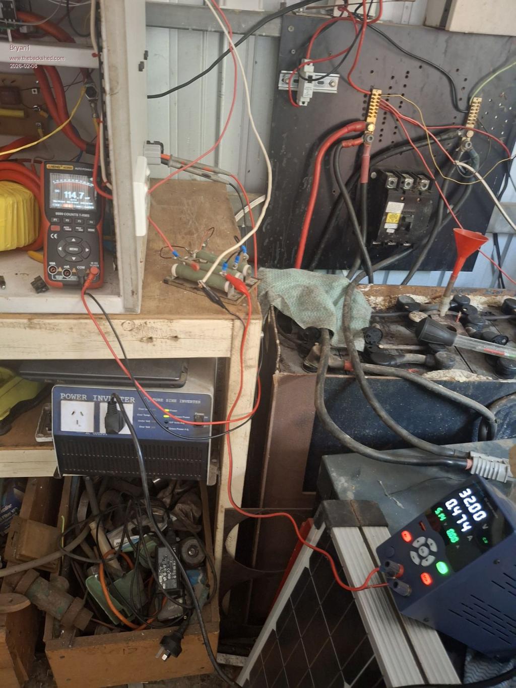 Now the fets aren't heating up at all but the resistor bank is around 75C The DMM is connected to the Anderson connector and the input power is coming from the back pads on the under side of the board. Now just turned it off and decided to put the DMM on resistance and sure enough I do have a short so got some investigations to do to find out where it is. Now I do wonder if it is the fets as no isolation was done and the fets just went straight onto the heatsinks. O'well all a learning curve and it does pay to crawl before walking  Edited 2026-02-08 17:00 by Bryan1 |
||||
| phil99 Guru Joined: 11/02/2018 Location: AustraliaPosts: 3317 |
32V / 0.474A = 57.5Ω 57.5 * 3 = 172.5Ω per resistor, so they are not the problem. |
||||
| Bryan1 Guru Joined: 22/02/2006 Location: AustraliaPosts: 2138 |
I did do a continuity test between the fet legs and the Anderson connector and both fet legs show the short so more investigation tomorrow when I take the board out. |
||||
| phil99 Guru Joined: 11/02/2018 Location: AustraliaPosts: 3317 |
If you can disconnect the capacitor bank you can test that and the inverter individually. Might save dismantling the inverter if the fault is on the cap. board. Edit. Ignore above. when I scrolled to the top I see the caps. are on the inverter board. Edited 2026-02-08 17:36 by phil99 |
||||
| Bryan1 Guru Joined: 22/02/2006 Location: AustraliaPosts: 2138 |
Phill there are 6 off 10,000uf 63 volt caps on the board between the heatsinks so no way of taking them off unless each are desoldered. Tomorrow I will take the heatsink off and see if that is the issue and have a real good look to see if there is anything causing the short. |
||||
| KeepIS Guru Joined: 13/10/2014 Location: AustraliaPosts: 2196 |
From memory, if the two short "split heat sinks" mounted on one side of the board are isolated, IE no phyical/electrical connection between the heat sinks, then you can mount the FETS directly to the Heatsinks. This should be fairly easy to check and diagnose. NANO:Inverter V 8.2ks - Linux AvrDude GUI script V4.1 |
||||
| The Back Shed's forum code is written, and hosted, in Australia. | © JAQ Software 2026 |
