|

|
Forum Index : Microcontroller and PC projects : PicoMite Alpha Firmware - a27 onwards - starting on displays
| Author | Message | ||||
| thwill Guru Joined: 16/09/2019 Location: United KingdomPosts: 4343 |
Hi Peter, I'm trying to port some CMM2 code to the PicoMite and was wondering if you might implement the additional MEMORY commands: Option Base 0 Option Default None Option Explicit Dim foo%(9) = (1,2,3,4,5,6,7,8,9,10) Dim bar%(9) Dim foo_addr% = Peek(VarAddr foo%()) Dim bar_addr% = Peek(VarAddr bar%()) Dim i% For i% = 0 To 9 : Print foo%(i%); " " ; : Next Memory Copy foo_addr%, foo_addr%, 80 For i% = 0 To 9 : Print bar%(i%); " " ; : Next > run "memory_test" 1 2 3 4 5 6 7 8 9 10 Program: 1K ( 1%) Program (15 lines) 79K (99%) Free RAM: 1K ( 0%) 5 Variables 0K ( 0%) General 111K (100%) Free 0 0 0 0 0 0 0 0 0 0 It looks like it just treats MEMORY COPY as if it were the vanilla MEMORY command, and I'm guessing that will be the same for MEMORY SET. Also any chance of support for: > Print Mm.Info(Option Base) Error : OPTION is not declared Thanks, Tom Edited 2021-07-11 20:55 by thwill MMBasic for Linux, Game*Mite, CMM2 Welcome Tape, Creaky old text adventures |
||||
| lizby Guru Joined: 17/05/2016 Location: United StatesPosts: 3614 |
Should it be necessary to re-issue the SETPINs for a uart when re-opening a com port which has been closed? > SetPin 21,uart0tx:SetPin 22,uart0rx > Open "com0:115200" As #1 > close #1 > Open "com0:115200" As #1 Error : Pins not set for UART0 > SetPin 21,uart0tx:SetPin 22,uart0rx > Open "com0:115200" As #1 > close #1 PicoMite, Armmite F4, SensorKits, MMBasic Hardware, Games, etc. on fruitoftheshed |
||||
| matherp Guru Joined: 11/12/2012 Location: United KingdomPosts: 10963 |
Yes Note to all: No updates for the next 3 weeks or so |
||||
| lizby Guru Joined: 17/05/2016 Location: United StatesPosts: 3614 |
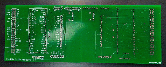
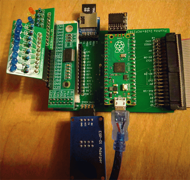
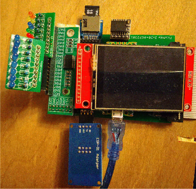
An update on Picromite PCBs I got the PCBs that I posted gerbers for here Because the PCB without the MCP23017 is identical except for that module, I started with the one which has the module.  I first soldered on the SD module and it tested OK. I soldered in male headers for the RTC module, and it wasn't recognized. I traced it to no ground on the RCT pins. I had run a trace from the middle point on the 3 pads at the bottom of the Pico, which I had somewhere seen was 0V--but I had no pin connecting it to the pad. I soldered a wire to 0V on the SD pins, and the RTC worked. The other 5 modules all worked--ILI9488 (with MISO snipped off), ESP-01 module, and MCP23017 module. The ESP-01 is upside down, but it doesn't care, even if I do.  And with ILI9341:  These are the modules: SD RTC LCD ESP-01 module MCP23017 module Next will be testing the 2x20 expansion port. PicoMite, Armmite F4, SensorKits, MMBasic Hardware, Games, etc. on fruitoftheshed |
||||
| Volhout Guru Joined: 05/03/2018 Location: NetherlandsPosts: 5698 |
I am glad to hear there was only 1 missing ground wire. Any concrete project in mind with this board ? Or is it just for experiments...? Volhout PicomiteVGA PETSCII ROBOTS |
||||
| lizby Guru Joined: 17/05/2016 Location: United StatesPosts: 3614 |
No particular project. This is the functionality I usually look at for a Micromite (ever since the MM+), and I wanted 2x20 connection compatibility with the CMM2 and with the F4 PCB I produced earlier. The MCP23017 was just because it's so easy to add, and who knows when the pins will be useful (model railroad controller, dollhouse lighting controller, etc.). PicoMite, Armmite F4, SensorKits, MMBasic Hardware, Games, etc. on fruitoftheshed |
||||
| The Back Shed's forum code is written, and hosted, in Australia. | © JAQ Software 2026 |