
|
|
Forum Index : Microcontroller and PC projects : PicoMite Alpha Firmware - a27 onwards - starting on displays
| Page 1 of 14 |
|||||
| Author | Message | ||||
| matherp Guru Joined: 11/12/2012 Location: United KingdomPosts: 10181 |
a27 PicomiteV5.07.00a27.zip 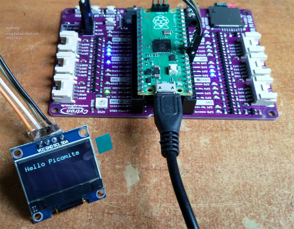 This version starts the process of implementing display support. This is based in the ArmmiteL4 but with a PicoMite twist. The first display implemented is an I2C SSD1306. This should be set to the default address (0x78/0x3C) In order to use the display we need to allocate the I2C pins. This works the same as the pins for the SDcard OPTION SYSTEM I2C sdapin, sclpin These pins must be valid I2C0 or I2C1 pins and will be configured to run at 400KHz. In future the SYSTEM I2C will also support a DS3231 RTC. Other devices can be connected to the I2C bus and accessed as usual with I2C READ and I2C WRITE. The I2C port does not need to be opened in this case. The display is then enabled with OPTION LCDPANEL SSD1306I2C, orientation or OPTION LCDPANEL SSD1306I2C32, orienation for the 128x32 version of the display If you can find a 1.3" version that works in I2C mode you can add a parameter offset to locate the image correctly Typically this would be: OPTION LCDPANEL SSD1306I2C, l, 2 All the usual graphics command should be there but testing is limited Edited 2021-06-20 20:32 by matherp |
||||
| thwill Guru Joined: 16/09/2019 Location: United KingdomPosts: 4299 |
Hi folks, Hope someone (and I know that probably means Peter) can tell me the idiot mistake I'm making. I'm using the same Maker Pi Pico pictured above and had the SD card working with a25, but both a26 and a27 have failed for me: > option list OPTION COLOURCODE ON OPTION CPUSPEED (KHz) 250000 OPTION SDCARD GP15, 10 OPTION SYSTEM SPI GP10,GP11,GP12 > files Error : A hard error occurred in the low level disk I/O layer > Warning: SDcard Removed - I have tried CPUSPEEDs of 200000 and 225000 with the same result - the ", 10" on the SDCARD line is new for a27, what does it mean ? - when I boot the GP12 and GP15 leds are lit - when I type "files" GP10 and 11 briefly pulse (11 *may* be pulsing twice), GP15 briefly extinguishes Best wishes, Tom MMBasic for Linux, Game*Mite, CMM2 Welcome Tape, Creaky old text adventures |
||||
| matherp Guru Joined: 11/12/2012 Location: United KingdomPosts: 10181 |
a28 PicomiteV5.07.00a28.zip RTC GETTIME, SETTIME, GETREG, SETREG now all supported. I2C channel must be set up with OPTION SYSTEM I2C before use. Tested with DS3231 and PCF8563 The extra parameter is the speed of the spi bus in MHz. I can run successfully up to 20MHz with a SanDisk Extreme Pro 32GB on the Maker board. Try starting at 1MHz and see what happens. The initialisation of the card is at 250KHz which should be OK for any card Edited 2021-06-21 02:18 by matherp |
||||
| thwill Guru Joined: 16/09/2019 Location: United KingdomPosts: 4299 |
Thanks Peter, Now updated to a28 but still not really getting anywhere c.f. a25 What does this mean ? When I do a vanilla OPTION SDCARD GP15 then I get a default of 10 MHz: > option list OPTION COLOURCODE ON OPTION CPUSPEED (KHz) 250000 OPTION SDCARD GP15, 10 OPTION SYSTEM SPI GP10,GP11,GP12 When I try to change the SDCARD option: > option sdcard gp15,1 Error : SDcard already configured Is this correct ? Is there a way to OPTION RESET a single option ? Or do I have to start from scratch ? Even if I start from scratch with OPTION SDCARD GP15, 1 then I *sometimes* get the previously reported Error. I am currently using a SanDisk Ultra 16GB: https://www.amazon.co.uk/dp/B0749WVNYG I guess I can spring for another to circumvent this roadblock, though longterm I suspect you don't want it to be so "picky". Is this the card you are using ? https://www.amazon.co.uk/dp/B06XYHN68L Best wishes, Tom MMBasic for Linux, Game*Mite, CMM2 Welcome Tape, Creaky old text adventures |
||||
| thwill Guru Joined: 16/09/2019 Location: United KingdomPosts: 4299 |
Example session with a29: > option list OPTION SDCARD GP15, 1 OPTION SYSTEM SPI GP10,GP11,GP12 > files Error : There is no valid FAT volume > files Error : A hard error occurred in the low level disk I/O layer > Warning: SDcard Removed files Error : A hard error occurred in the low level disk I/O layer > Warning: SDcard Removed files Error : There is no valid FAT volume > files Error : There is no valid FAT volume > files Error : A hard error occurred in the low level disk I/O layer > Warning: SDcard Removed files Error : There is no valid FAT volume > files Error : Not enough memory > files Error : Not enough memory > - The FAT volume does appear to be intact, Linux can read it anyway. - In the first session after OPTION GP15, 1 instead of the FAT error the command would actually run correctly. Restored a25 and with the same card: > option list OPTION SDCARD GP15 OPTION SYSTEM SPI GP10,GP11,GP12 > files A:/ <DIR> scratch 21 goodbye.bas 60 hello.bas 1 directory, 2 files - It does require a reboot after setting OPTION SDCARD for the SDcard to be found. Best wishes, Tom MMBasic for Linux, Game*Mite, CMM2 Welcome Tape, Creaky old text adventures |
||||
| matherp Guru Joined: 11/12/2012 Location: United KingdomPosts: 10181 |
Use option sdcard disable then option sdcard pin, speed You seem to have reported SDcard issues which others aren't seeing so I'm wondering if there is a poor connection on your board. I've just tried a range of cards including an old 2Gb one that predates the class system and even that works fine. All SDcards in theory should work up to 25MHz on SPI but that assumes perfect power and transmission lines. The other thing you could try is a better power source to the Pico Edited 2021-06-21 04:49 by matherp |
||||
| thwill Guru Joined: 16/09/2019 Location: United KingdomPosts: 4299 |
Thanks Peter, I'll try that out tomorrow and also test this SDcard in case I got sold a fake. Best wishes, Tom MMBasic for Linux, Game*Mite, CMM2 Welcome Tape, Creaky old text adventures |
||||
| Mixtel90 Guru Joined: 05/10/2019 Location: United KingdomPosts: 7820 |
Update to my little help file: Picomite doc a28.zip Mick Zilog Inside! nascom.info for Nascom & Gemini Preliminary MMBasic docs & my PCB designs |
||||
| Mixtel90 Guru Joined: 05/10/2019 Location: United KingdomPosts: 7820 |
Using a28 OPTION SDCARD GP1,10 is working fine for me, Tom. OPTION SYSTEM I2C GP20, GP21 (I2C0) is accepted RTC GETTIME and RTC SETTIME both give a RTC not responding error. The RTC is one of the blue DS3231 modules with a memory chip on board. RTC address is 0x68 R/W (I don't think this can be changed) EEPROM address is 0xA0 write and 0xA1 read by default It works fine at 400kHz using the Micromite library. OPTION SYSTEM I2C DISABLE doesn't seem to free off the pins. After a reset, without setting SYSTEM I2C, the library uses the pins and works fine. Mick Zilog Inside! nascom.info for Nascom & Gemini Preliminary MMBasic docs & my PCB designs |
||||
disco4now Guru Joined: 18/12/2014 Location: AustraliaPosts: 1000 |
Same for me. Tried a couple of different ones.Added 4.7K pullups. SSD1306I2C32 on same pins seems OK Edited 2021-06-21 17:44 by disco4now Latest F4 Latest H7 FotS |
||||
| matherp Guru Joined: 11/12/2012 Location: United KingdomPosts: 10181 |
Please try RTC on a pair of I2C1 pins |
||||
| cdeagle Senior Member Joined: 22/06/2014 Location: United StatesPosts: 265 |
I am running with the following OPTIONs without any problems. OPTION SDCARD GP5, 10 OPTION SYSTEM SPI GP2,GP3,GP4 OPTION SYSTEM I2C GP6,GP7 |
||||
| Mixtel90 Guru Joined: 05/10/2019 Location: United KingdomPosts: 7820 |
I'm away from that PicoMite at the moment - I'll test it when I get home this afternoon. I have the other, but no RTC or SD card for this one. Mick Zilog Inside! nascom.info for Nascom & Gemini Preliminary MMBasic docs & my PCB designs |
||||
| thwill Guru Joined: 16/09/2019 Location: United KingdomPosts: 4299 |
Thanks Peter, I'm using short, thick, branded Amazon USB cables which have always been reliable for me before. I've no way of actually testing them but I doubt they are a problem. I tested the 16 GB SanDisk Ultra with H2testw and it seems to be OK. The Maker Pi Pico can read the FAT (not 32) partition from an SD card I pulled from a Raspberry Pi - I don't have an accumulation of SD cards which is why it isn't something I can easily test. Finally I pulled the Pico from the board and wired it directly to one of those little SD card breakouts on the same pins and that appears to work !!! Would you say that is enough to return the Maker Pi Pico as defective ? - the components are a bit small and I don't have any lead-free solder with which to attempt any rework myself. Best wishes, Tom MMBasic for Linux, Game*Mite, CMM2 Welcome Tape, Creaky old text adventures |
||||
| matherp Guru Joined: 11/12/2012 Location: United KingdomPosts: 10181 |
Note you can't use pins GP18, GP19, GP20, GP21 or GP22 for I2C on the Maker board as these are wired to switches and/or the audio port in an incompatible way |
||||
| matherp Guru Joined: 11/12/2012 Location: United KingdomPosts: 10181 |
Yes, you can explain that another user is using the same S/W on the same board without issue and that you have wired a SD socket separately and that works OK. |
||||
| thwill Guru Joined: 16/09/2019 Location: United KingdomPosts: 4299 |
Yes, and I've just now wired that breakout to GP2-5 on the maker board and that works too, so the only variable is the SD card socket (and connections to it) on the maker board itself. Thanks, Tom MMBasic for Linux, Game*Mite, CMM2 Welcome Tape, Creaky old text adventures |
||||
| disco4now Guru Joined: 18/12/2014 Location: AustraliaPosts: 1000 |
I moved from GP20 and GP21 (I2C) where RTC did not respond to GP18 and GP19 (I2C1) and RTC seems to be OK now. LCD was OK on both. Latest F4 Latest H7 FotS |
||||
| matherp Guru Joined: 11/12/2012 Location: United KingdomPosts: 10181 |
a29 Fixes RTC command on I2C0 pins - but beware pin usage on Maker PCB More display support but no touch yet PicomiteV5.07.00a29.zip The PicoMite supports a wide range of displays. Not all tested SSD1306 controller 128x64 pixel OLED, 0.96" and 1.3" with I2C I/F, monochrome SSD1306 controller 128x32 pixel OLED, 0.1" with I2C I/F, monochrome SSD1306 controller 128x64 pixel OLED, 0.96" and 1.3" with SPI I/F, monochrome SSD1306 controller 128x32 pixel OLED, 0.1" with SPI I/F, monochrome ST7920 controller 128x64 pixel LCD, 3.25" with SPI I/F, monochrome Nokia 5110 controller 84x48 pixel LCD, with SPI I/F, monochrome GDEH029A1 controller 128x296 pixel e-ink, with SPI I/F, monochrome ILI9163 controller 128x128 pixel TFT, 1.44" with SPI I/F, RGB565 ILI9341 controller 320x240 pixel TFT, 2.2", 2.4", 2.8" with SPI I/F, RGB565 ST7735 controller 160x128 pixel TFT, 1.8" with SPI I/F, RGB565 ST7735S controller 160x80 pixel IPS, 0.96" with SPI I/F, RGB565 SSD1331 controller 96x64 pixel OLED, 0.95" with SPI I/F, RGB565 ST7789 controller 240x240 pixel IPS, 1.3" with SPI I/F, RGB565 ILI9481 controller 480x320 pixel TFT, 3.5", 4" with SPI I/F, RGB565 ILI9488 controller 480x320 pixel TFT, 3.5", 4" with SPI I/F, RGB666 Connecting SPI Based LCD Panels The SPI based display controllers share the SYSTEM SPI channel (SPI2) interface on the PicoMite with the touch controller (if present) and the SDcard. The pins allocated to the SYSTEM SPI will not be available to other MMBasic commands. The speed of drawing to SPI based displays will be laregely unaffected by the CPU speed. Connecting I2C Based LCD Panels The I2C based display controllers use the SYSTEM I2C pins as per the pinout for the specific device. Other I2C devices can share the bus subject to their addresses being unique. If an I2C display is configured it will not be necessary to "open" the I2C port for an additional device (I2C OPEN ), I2C CLOSE is blocked, and all I2C devices must be capable of 400KHz operation. The I2C bus speed is not affected by changes to the CPU clock speed. OPTION LCDPANEL GDEH029A1, orientation, DCpin, RESETpin, CSpin, BUSYpin [,refreshcount] Initialises an e-Ink display using the GDEH029A1controller. This supports 128 * 296 resolution. See " OPTION LCDPANEL ILI9341" for details of main parameter usage. 'BUSYpin' is an input used by the driver to establish command completion on the slow e-Ink display. An additional parameter refreshcount may be specified to control when the driver does a full update to the display (black/white flash). Default is 1. i.e. the display does a full refresh each write. Setting a bigger value can make updates faster and less obvious but with the risk of permanently creating ghost images on the display. OPTION LCDPANEL ILI9163, orientation, DCpin, RESETpin, CSpin Initialises a TFT display using the ILI9163 controller. This supports 128 * 128 resolution. See " OPTION LCDPANEL ILI9341" for details of parameter usage. OPTION LCDPANEL ILI9341, orientation, DCpin, RESETpin, CSpin Configures the Micromite and Micromite Plus to work with an attached TFT panel using the ILI9341 controller. This supports 320 * 240 resolution. 'orientation' can be LANDSCAPE, PORTRAIT, RLANDSCAPE or RPORTRAIT. These can be abbreviated to L, P, RL or RP. The R prefix indicates the reverse or "upside down" orientation. 'C/D pin', 'reset pin' and 'CS pin' are the Micromite I/O pins to be used for these functions. Any free pin can be used. OPTION LCDPANEL ILI9481, orientation, DCpin, RESETpin, CSpin Initialises a TFT display using the ILI9481 controller. This supports 480 * 320 resolution. See " OPTION LCDPANEL ILI9341" for details of parameter usage. OPTION LCDPANEL ILI9488, orientation, DCpin, RESETpin, CSpin Initialises a TFT display using the ILI9488 controller. This supports 480 * 320 resolution. See " OPTION LCDPANEL ILI9341" for details of parameter usage. OPTION LCDPANEL N5110, orientation, DCpin, RESETpin, CSpin [,contrast] Initialises a LCD display using the Nokia 5110 controller. This supports 84 * 48 resolution. See " OPTION LCDPANEL ILI9341" for details of main parameter usage. An additional parameter LCDVOP may be specified to control the contrast of the display. Try contrast values between &HA8 and &HD0 to suit your display, default if omitted is &HB1 OPTION LCDPANEL SSD1306I2C, orientation [,offset] Initialises a OLED display using the SSD1306 controller with an I2C interface. This supports 128 * 64 resolution. See " OPTION LCDPANEL ILI9341" for details of parameter orientation. An additional parameter offset may be specified to control the position of the display. 0.96" displays typically need a value of 0. 1.3" displays typically need a value of 2. Default if omitted is 0. NB many cheap I2C versions of SSD1306 displays do not implement I2C properly due to a wiring error. This seems to be particularly the case with 1.3" variants OPTION LCDPANEL SSD1306I2C32, orientation Initialises a OLED display using the SSD1306 controller with an I2C interface. This supports 128 * 32 resolution. See " OPTION LCDPANEL ILI9341" for details of parameter orientation. OPTION LCDPANEL SSD1306SPI, orientation, DCpin, RESETpin, CSpin [,offset] Initialises a OLED display using the SSD1306 controller with an SPI interface. This supports 128 * 64 resolution. See " OPTION LCDPANEL ILI9341" for details of main parameter usage. An additional parameter offset may be specified to control the position of the display. 0.96" displays typically need a value of 0. 1.3" displays typically need a value of 2. Default if omitted is 0. OPTION LCDPANEL SSD1331, orientation, DCpin, RESETpin, CSpin Initialises a colour OLED display using the SSD1331 controller. This supports 96 * 64 resolution. See " OPTION LCDPANEL ILI9341" for details of parameter usage. OPTION LCDPANEL ST7735, orientation, DCpin, RESETpin, CSpin Initialises a TFT display using the ST7735 controller. This supports 160 * 128 resolution. See " OPTION LCDPANEL ILI9341" for details of parameter usage. OPTION LCDPANEL ST7735S, orientation, DCpin, RESETpin, CSpin Initialises a IPS display using the ST7735S controller. This supports 160 * 80 resolution. See " OPTION LCDPANEL ILI9341" for details of parameter usage. OPTION LCDPANEL ST7789, orientation, DCpin, RESETpin, CSpin Initialises a IPS display using the 7789 controller. This supports 240 * 240 resolution. See " OPTION LCDPANEL ILI9341" for details of parameter usage. OPTION LCDPANEL ST7920, orientation, DCpin, RESETpin Initialises a LCD display using the ST7920 controller. This supports 128 * 64 resolution. Note this display does not support a chip select so cannot so the SPI bus cannot be shared if this display is used. See " OPTION LCDPANEL ILI9341" for details of other parameter usage. |
||||
| thwill Guru Joined: 16/09/2019 Location: United KingdomPosts: 4299 |
Are the sizes of small LCD panels measured the same as TVs, i.e. across the diagonal ? Edited 2021-06-21 22:49 by thwill MMBasic for Linux, Game*Mite, CMM2 Welcome Tape, Creaky old text adventures |
||||
| Page 1 of 14 |
|||||
| The Back Shed's forum code is written, and hosted, in Australia. | © JAQ Software 2025 |
