
|
|
Forum Index : Electronics : Bryan's Inverter build
| Author | Message | ||||
Bryan1 Guru Joined: 22/02/2006 Location: AustraliaPosts: 2138 |
Ok took one side of the AC off and put my DMM on AC voltage, connected the power supply and the green led on the power goes out also the other fluke scope meter was only showing milli volts so the short is on the power board. |
||||
| KeepIS Guru Joined: 13/10/2014 Location: AustraliaPosts: 2196 |
I hate to NAG: I know we have been over this, but since damage was caused last time: I hope you have that power supply limited to less than 1A and "slowly increase the voltage" each time, [OR] put a resistor 30 to 60 ohm, 5 watt, in-line when testing - AND discharge the caps with the same 47ohm resistor each time. As you have the caps connected, soldered, if/when the voltage gets to your system voltage, any mistake or slip up, and the caps (just the CAPS) can/will blow your FETS.  NANO:Inverter V 8.2ks - Linux AvrDude GUI script V4.1 |
||||
Revlac Guru Joined: 31/12/2016 Location: AustraliaPosts: 1282 |
Also agree with comment above. Brian, did you (or someone else) see the last Gerber PCB mad board file, there might have been some changes to the power board Depending on which board you have, the latest has a 10K on Pin 1 of the TIP35C, as well as the 18v Zener, my board has not got the 10K, not sure if there was anything else, or if that is correct? 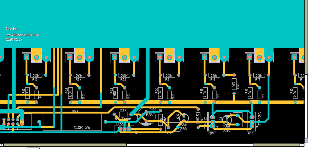 Don't want to create any confusion, but worth checking solder joints around the TIP41 and 42C just to be sure. Cheers Aaron Off The Grid |
||||
| Bryan1 Guru Joined: 22/02/2006 Location: AustraliaPosts: 2138 |
Hi Aaron I do have that latest board but that 100uf cap is around the other way 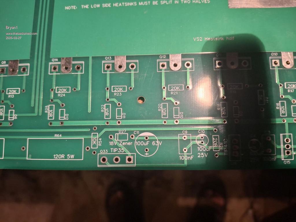 Now Keepis I always use that 60 ohm 120 watt bank of resistors and have a voltage meter attached also with the programmable power supply shows the current draw and on charging 400mA was the highest current until the caps got to 20 volts then the current draw dropped to 50mA. |
||||
| KeepIS Guru Joined: 13/10/2014 Location: AustraliaPosts: 2196 |
Both boards look right with respect to the CAP, different tracks, unless I'm blind. Brian, thats good that you are still using the resistors BUT if the voltage gets to 20V, then the resistor and the current limit mean NOTHING! If you were to make a slip up when measuring components OR plugging in or disconnecting the Ribbon cable to the power board, Then the Charged caps, of the value you have, could deliver over a 1000A pulse to the FETS. . Edited 2026-02-27 13:38 by KeepIS NANO:Inverter V 8.2ks - Linux AvrDude GUI script V4.1 |
||||
| Bryan1 Guru Joined: 22/02/2006 Location: AustraliaPosts: 2138 |
Keepis one time I took the ribbon cable it did spark now I don't know whether this is any good but I measured in relation to the gate the resistance. Gate to centre pin 1.035 Mohm Gate to other pin 1.946Kohm Trying a few fets they all show the same value too. |
||||
| KeepIS Guru Joined: 13/10/2014 Location: AustraliaPosts: 2196 |
If the power board "unplugged" from the Controller, comes up to the supply rail via the resistors, then the problem is either the controller board is not outputting the correct signals, a wiring error in the ribbon cable, or an error in the FET drivers. NANO:Inverter V 8.2ks - Linux AvrDude GUI script V4.1 |
||||
| Bryan1 Guru Joined: 22/02/2006 Location: AustraliaPosts: 2138 |
Keepis if it does come down to a ribbon cable I made then I better get one made as my attempts were maybe too heavy handed. Now the control board was remade with all new components and I did get extra fet driver chips. The power board does come up to VBAT or just below it and the green led on the board does light up. Tomorrow I will hookup my scope and do the tests to see what signals are coming from the ribbon cable where TinyT gave all the hookup details on a previous page. When I got Roger to solder on those heavy wires we did look over the board and found no errors. Now the fact with the ribbon cable not connected the LCD is showing the inverter is on and the TOR and HS temps are reading OK and changing with the temps. As far as the wrong code only Poida can answer that question as I am using the codes he sent me. But the LCD serial code didn't work where the LCD from my MTTP project worked so the control board is working but the BV is showing 0.0. The VBat connection on the control board was left blank as last time it vaporized so that maybe the reason the BV is showing zero. Edited 2026-02-27 16:06 by Bryan1 |
||||
| KeepIS Guru Joined: 13/10/2014 Location: AustraliaPosts: 2196 |
Yes likely, if you are worried, put a 1K resistor in series with the VBat connection to the board, it might read slightly off, but at least you can test it correctly. NANO:Inverter V 8.2ks - Linux AvrDude GUI script V4.1 |
||||
| Bryan1 Guru Joined: 22/02/2006 Location: AustraliaPosts: 2138 |
Good suggestion mate now as I left the breadboard connector off the VBat + connection from that rear VBat I made I could easily make a cable with that 1K resistor and plug it into the VBat pin on the 10 pin connector. |
||||
| tinyt Guru Joined: 12/11/2017 Location: United StatesPosts: 561 |
Make sure that the power board is good before you plug the 10-pin connector from the brainboard. On the power board, double check orientation of the electrolytic capacitors, diodes, and transistors. Make sure the TIP41's and the TIP42's are in their right places with correct orientation. You can do a rough shorted check on the installed mosfets using an ohmmeter. I assume the TIP35 is an 18-volt linear regulator if D27 is an 18 volt zener. Is it outputting regulated 18 volts if the input voltage is 20 volts or higher? |
||||
| Bryan1 Guru Joined: 22/02/2006 Location: AustraliaPosts: 2138 |
Ok with this wet weather got the noise of my genset going to charge the shed battery. Anyway powered up the controller board and measured 17.8 volts on the 18V zener, now when the ohm meter is used the Vbat + and VBat - are shorted out. Doing an ohm check on a few fets shows the gate is isolated and the source and drain pins are a dead short, so would this mean the fets are gone? Anyway setup the scope and got a pic of the L01 and L02 first test 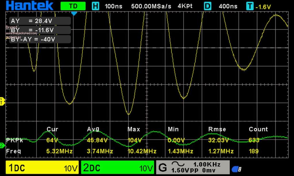 Regards Bryan |
||||
| Godoh Guru Joined: 26/09/2020 Location: AustraliaPosts: 675 |
Hi Bryan, is the FETs show short on an ohm meter they are most likely dead. I would suggest removing one that shows the short and checking it off the board. That will rule out other components being shorted. Good luck Pete |
||||
| Bryan1 Guru Joined: 22/02/2006 Location: AustraliaPosts: 2138 |
Well I had to to get and get some fuel for the gensets as this seems like the first time they have run since last winter and had a bit of a think about this. Got home and checked a new fet and this time didn't have the ohm meter on beep  now between the source and drain it around 90K ohms on the new one and on testing the front bank of fets they all show around the ohms as the new one so I don't think the fets are gone. now between the source and drain it around 90K ohms on the new one and on testing the front bank of fets they all show around the ohms as the new one so I don't think the fets are gone.Now this morning I did notice some metal shavings on the front of the power board so when later this arvo I'll give the board a blast of compressed air and check again. Regards Bryan Edit just gave the power board a blast of compressed air and tried again where I limited the current to 200mA @24 volts. With the ribbon cable connected the voltage is 0.1V and the full 200mA is used. Take the ribbon cable off and the voltage when rising didn't even take 150mA. Now I have put the ohm meter on the Vbat+ and Vbat - pins and the ohms starting around 90 ohm and has risen to 600ohm over about a minute and is slowly rising. Edited 2026-03-01 13:41 by Bryan1 |
||||
| KeepIS Guru Joined: 13/10/2014 Location: AustraliaPosts: 2196 |
It look like the FETS are being turned on hard, so incorrect drive signals for a number of reasons, or a power board problem somewhere ???? Can't be of much help without being there   NANO:Inverter V 8.2ks - Linux AvrDude GUI script V4.1 |
||||
| Bryan1 Guru Joined: 22/02/2006 Location: AustraliaPosts: 2138 |
Hi Keepis as your fluent with Arduino attached is pico_2_heavy_filter_bv_better_stop_prefect_symmetry.zip So if you take a quick look at the file for me it would be great Regards Bryan |
||||
| tinyt Guru Joined: 12/11/2017 Location: United StatesPosts: 561 |
They should not be the L01 and L02 of the un-driven power board. They should be the L01 and L02 signals coming from the controller board. |
||||
| KeepIS Guru Joined: 13/10/2014 Location: AustraliaPosts: 2196 |
That Arduino file looks fine to me, provided it's the one that Poida designed for that controller, mainly pin assignment etc. Unfortunately I have no knowledge or info on that Controller or power board. Mike. Edited 2026-03-01 14:49 by KeepIS NANO:Inverter V 8.2ks - Linux AvrDude GUI script V4.1 |
||||
| Bryan1 Guru Joined: 22/02/2006 Location: AustraliaPosts: 2138 |
TinyT I put a 10 connector on the end of the ribbon cable where VS1 and VS2 were connected to the ground on the connector. Now decided to reprogram the nano and this is the output from avrdude for me each time sudo avrdude -v -c usbasp -p m328P -F -v -U flash:w:/home/Bryan/Documents/inverter.hex:i Avrdude version 8.1 Copyright see https://github.com/avrdudes/avrdude/blob/main/AUTHORS System wide configuration file is /home/Bryan/Documents/avrdude.conf User configuration file /root/.avrduderc does not exist Using port : usb Using programmer : usbasp Seen device from vendor >www.fischl.de< Seen product >USBasp< AVR part : ATmega328P Programming modes : SPM, ISP, HVPP, debugWIRE Memory Size Pg size ------------------------------ eeprom 1024 4 flash 32768 128 lfuse 1 1 hfuse 1 1 efuse 1 1 lock 1 1 prodsig/sigrow 24 1 sernum 10 1 io 224 1 sram 2048 1 signature 3 1 calibration 1 1 Variants Package F max T range V range ---------------------------------------------------------------- ATmega328P N/A 20 MHz [-40 C, N/A] [1.8 V, 5.5 V] ATmega328P-15MZ MLF32 20 MHz [-40 C, 85 C] [1.8 V, 5.5 V] ATmega328P-AN TQFP32 20 MHz [-40 C, 105 C] [1.8 V, 5.5 V] ATmega328P-ANR TQFP32 20 MHz [-40 C, 105 C] [1.8 V, 5.5 V] ATmega328P-AU TQFP32 20 MHz [-40 C, 85 C] [1.8 V, 5.5 V] ATmega328P-AUR TQFP32 20 MHz [-40 C, 85 C] [1.8 V, 5.5 V] ATmega328P-MMH MLF28 20 MHz [-40 C, 85 C] [1.8 V, 5.5 V] ATmega328P-MMHR MLF28 20 MHz [-40 C, 85 C] [1.8 V, 5.5 V] ATmega328P-MN QFN32 20 MHz [-40 C, 105 C] [1.8 V, 5.5 V] ATmega328P-MNR MLF32 20 MHz [-40 C, 105 C] [1.8 V, 5.5 V] ATmega328P-MU MLF32 20 MHz [-40 C, 85 C] [1.8 V, 5.5 V] ATmega328P-MUR MLF32 20 MHz [-40 C, 85 C] [1.8 V, 5.5 V] ATmega328P-PN PDIP28 20 MHz [-40 C, 105 C] [1.8 V, 5.5 V] ATmega328P-PU PDIP28 20 MHz [-40 C, 85 C] [1.8 V, 5.5 V] Programmer type : usbasp Description : USBasp ISP and TPI programmer Auto set sck period Error usbasp_spi_set_sck_period() usbasp.c 1031: cannot set sck period; please check for usbasp firmware update AVR device initialized and ready to accept instructions Reading | ################################################## | 100% 0.00 s Device signature = 1E 95 16 (ATmega328PB) Warning main() main.c 1781: expected signature for ATmega328P is 1E 95 0F Auto-erasing chip as flash memory needs programming (-U flash:w:...) specify the -D option to disable this feature Auto set sck period Error usbasp_spi_set_sck_period() usbasp.c 1031: cannot set sck period; please check for usbasp firmware update Erased chip Reading 10214 bytes for flash from input file inverter.hex in 2 sections of [0, 0x7f9d]: 81 pages and 154 pad bytes Writing 10214 bytes to flash Writing | ################################################## | 100% 6.39 s Reading | ################################################## | 100% 5.27 s 10214 bytes of flash verified Avrdude done. Thank you. It's that error usbasp spi set_sck period that may not be programming the nano Edited 2026-03-01 14:58 by Bryan1 |
||||
| KeepIS Guru Joined: 13/10/2014 Location: AustraliaPosts: 2196 |
Yes that is fine, but verbose output is set to -v -v If you are using my GUI, the command line in the setting file must have the lower case -v removed. You then set the desired level of info by changing the Verbose: current = 0, in the GUI, 0 is all you need once you have everything working. -p m328P -F -v -U ^ | remove This one That is not a problem FYI: You can upload a new version of firmware into the Programmer, I did the other day, it fixes those error messages. Your Nano was programmed correctly and verified. . Edited 2026-03-01 15:14 by KeepIS NANO:Inverter V 8.2ks - Linux AvrDude GUI script V4.1 |
||||
| The Back Shed's forum code is written, and hosted, in Australia. | © JAQ Software 2026 |
