
|
|
Forum Index : Electronics : Bryan's Inverter build
| Author | Message | ||||
Bryan1 Guru Joined: 22/02/2006 Location: AustraliaPosts: 2138 |
Keepis I did try your gui but the path.ini failed so in the end I just went with the commandline avrdude |
||||
| KeepIS Guru Joined: 13/10/2014 Location: AustraliaPosts: 2196 |
You need the GUI script and the settings file in the same directory. From the GUI click the Help button, and it will tell you what should be in the file and the correct name of the file. No problems, when you get the inverter sorted, we can always look further into it.  NANO:Inverter V 8.2ks - Linux AvrDude GUI script V4.1 |
||||
| tinyt Guru Joined: 12/11/2017 Location: United StatesPosts: 561 |
Your scope H setting should be in the milliseconds and not nanoseconds so that you can display at least 3 cycles of 50Hz. |
||||
| Bryan1 Guru Joined: 22/02/2006 Location: AustraliaPosts: 2138 |
Any finally noticed that cable on the avrdude was a 10 pin one just long enough to reach the power board so gave it a test.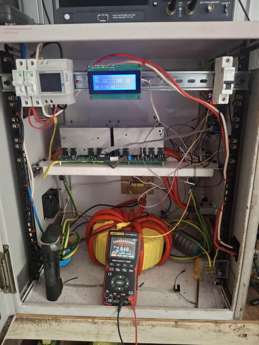 So the BV is working and showing the same voltage as my old fluke scope meter and I tried first @ 24 volts and 200mA where the BV stopped at 11.1 volts so turned off the PSU and adjust the current to 400mA. When turned it back on the current went to 207mA. Now upping the voltage to 27 volts didn't change the BV voltage. Now I did another test with my fluke scope meter and moved the Vbat voltage to 28 volts which did see the AC voltage to a whole 3 volts where the fluke was a clean sinewave and 49hz. So first signs of life Silly me did have the 10 pin backwards  so I am wondering those new fet drivers may have quietly let out the magic smoke. so I am wondering those new fet drivers may have quietly let out the magic smoke.Edited 2026-03-02 16:23 by Bryan1 |
||||
| Bryan1 Guru Joined: 22/02/2006 Location: AustraliaPosts: 2138 |
Ok just spent a few hours putting the pin connectors for all the wiring and put new 2184 fet driver chips in and still got that BV stuck at 11.1 volts with 28 volts input. Now take the ribbon cable off which is the correct way this time and the Vbat goes straight upto 24 volts with less than 100mA of current.So with a new control board all with new parts and I did do several checks to ensure all components are in correct. I'm now at a loss at what is wrong as everything is connected properly and that green led on the power board stayed on with the test above. Regards Bryan |
||||
Revlac Guru Joined: 31/12/2016 Location: AustraliaPosts: 1282 |
Bryan, I might get a chance tonight to look at it, or tomorrow, already loaded the code (on previous page) and it ran ok, At around 20v from the power supply green light on and running I had 15Vac at the power board primary, No toroid connected, I did try a small scope on the primaries and its quit choppy as expected with no filters or caps. Will get back later, but it seems like your very close to running. Edited 2026-03-03 16:28 by Revlac Cheers Aaron Off The Grid |
||||
| Bryan1 Guru Joined: 22/02/2006 Location: AustraliaPosts: 2138 |
Well took the power board out this morning and nothing looked out of place although I did clean off the flux from around the solder pads to clean it up. Did an ohm check on all the fets and all of them were same with drain measuring around 196K so they all look ok. Put the board back in and no change with a 28 volt 300mA input it's drawing 255mA and the BV is staying around 11 volts so no change. |
||||
| Revlac Guru Joined: 31/12/2016 Location: AustraliaPosts: 1282 |
With power off and the 10 pin connector removed from the controller pcb I measured 55k between the 60V supply terminal and pinA3 on the nano on the 2 controllers I have, this is for the battery voltage sense, I still don't have a display connected yet to check and see the BV on the screen when its up and running. Edited 2026-03-04 12:35 by Revlac Cheers Aaron Off The Grid |
||||
| Bryan1 Guru Joined: 22/02/2006 Location: AustraliaPosts: 2138 |
Ok I did take out the ribbon cable from the control board and got the same 55K from the 60 volt to A3 but get this those 60 volt pins on the connector aren't even connected on the control board and I left that Vbat rail(60 volt) connection off due to the burn out last time. Now also with the ribbon cable disconnected the VBat shown on my DMM is 24 volts from the 28 volt input supply where the current was only 75mA. Now with the ribbon in place the BV is 11.3 volts with a 254mA draw, the green led on the power is lit. Tracing the path of A3 goes to one side of two 15K resistors where one input to the 15K is 51K with then goes to the 60 volt pin. So for 24 volts would these resistors need changing to suit the lower voltage. Edited 2026-03-04 14:42 by Bryan1 |
||||
| Bryan1 Guru Joined: 22/02/2006 Location: AustraliaPosts: 2138 |
Ok so I look at the code where things could be tweaked if I'm right. #define LV_CUT_OFF 22 // minimum battery volts for inverter to run #define LV_RESTART 22.5 // restart volts #define LV_STOP_ENABLE 0 // = 1 to allow LV cut-off, = 0 to just keep running no matter battery voltage #define LV_ENABLE 0 // = 1 to permit LV restart if battery increases enough, = 0 to disable #define LV_TIMEOUT 5 // how many seconds BV needs to be below LV_CUT_OFF. Noise filter #define ADC_OUT 0 // channel for AC output sample #define HS_NTC 1 // and others #define TOR_NTC 2 #define BV 3 #define BV_SCALE 0.05986 // or something. Set it via trial and error. So the 22 volt LV_CUT_OFF is what I changed in the code and with if the BV_SCALE was changed to suit the low voltage I'm seeing tweaked to suit could this problem be overcome. May be time to get my 5 metre usb cable out so the nano can be reprogrammed in circuit so this can be tested out. Edit: ok got the BV on the lcd reading 15 volts but the voltage shown on the DMM where it connected to the resistor bank is staying on 11.4 volts. So tweaking the code isn't the problem... Edited 2026-03-04 15:49 by Bryan1 |
||||
| KeepIS Guru Joined: 13/10/2014 Location: AustraliaPosts: 2196 |
1: That will not cause the power-board to draw excessive current. 2: Both LV conditions are disabled. If the signals from the Controller are correct and there is no fault with the Power board or Toroid or wiring, then the inverter should run. NANO:Inverter V 8.2ks - Linux AvrDude GUI script V4.1 |
||||
| Bryan1 Guru Joined: 22/02/2006 Location: AustraliaPosts: 2138 |
OK with the nano turned off via the switch the voltage did rise to 25 volts now when the switch is turned on the Vbat drops pretty quick to that 11.4 volts and the inverter doesn't start. I just need to tweak that 0.0598 to suit the voltage on the DMM. So thats the problem I need to overcome. Edited 2026-03-04 16:29 by Bryan1 |
||||
| KeepIS Guru Joined: 13/10/2014 Location: AustraliaPosts: 2196 |
If you measure 11.4 volts across the power board supply then, that is the problem, not the reading on the LCD. What is the voltage across the B+ and B- terminals on the power board. I'm unsure of just what voltages you are actually measuring?? NANO:Inverter V 8.2ks - Linux AvrDude GUI script V4.1 |
||||
| Bryan1 Guru Joined: 22/02/2006 Location: AustraliaPosts: 2138 |
Keepis the DMM measuring the voltage is on the resistor bank output, now when the nano is turned off via the on/off switch both the DMM and BV on the lcd show 24 volts now as I turn the on/off switch on the voltage quickly drops to 11.4 volts. Now the green led on the power board stays on and the led on the nano doesn't flicker or anything like that. It does seem to me the TIP 41 and 42 chips may need replacing as when that spark happened earlier on may of been the kiler. |
||||
| tinyt Guru Joined: 12/11/2017 Location: United StatesPosts: 561 |
You should make sure that both power board and nano board are working properly prior to connecting them together with the 10-pin ribbon cable. Otherwise you will keep damaging components. As in my earlier post, you can check the controller board by powering it with 15 volts, and scoping the output signals. I don't have the controller board you are using, but my estimate is it should draw no more than 50 mA. To avoid possible shorts during testing, I would also spend some time to make a test ribbon cable with a connector at one end and bare wires at the other end for the following pin numbers: 3: L01 test point 4: H02 test point 5: VS1 connected to pin 9(gnd) (can be used as 'scope probe ground) 7: H01 test point 8: VS2 connected to pin 10(gnd) (can be used as 'scope probe ground) 9: GND connected to pin 5 (can be used as 'scope probe ground) 10: GND connected to pin 8 (can be used as 'scope probe ground) During testing, avoid the test point wires from touching any other wires. Otherwise, you can damage the IR2184's. Been there countless times.  Here is graphic picture of the board, courtesy of poida, with notes for reference. 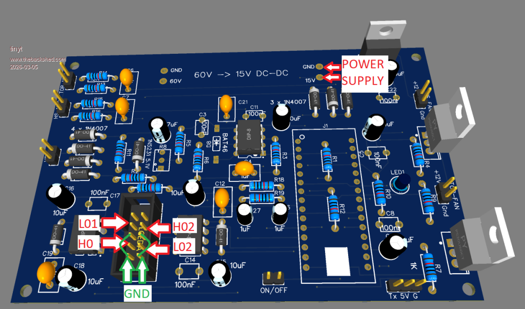 With the scope probes connected, apply the 15 volts power and turn on the on/off switch, and set the 'scope to capture the signal waveforms. Also, here are some scope screen captures of the test points for reference. Note the settings pointed to by the 3 red arrows. This is for L01(Yellow) and H01(Green) 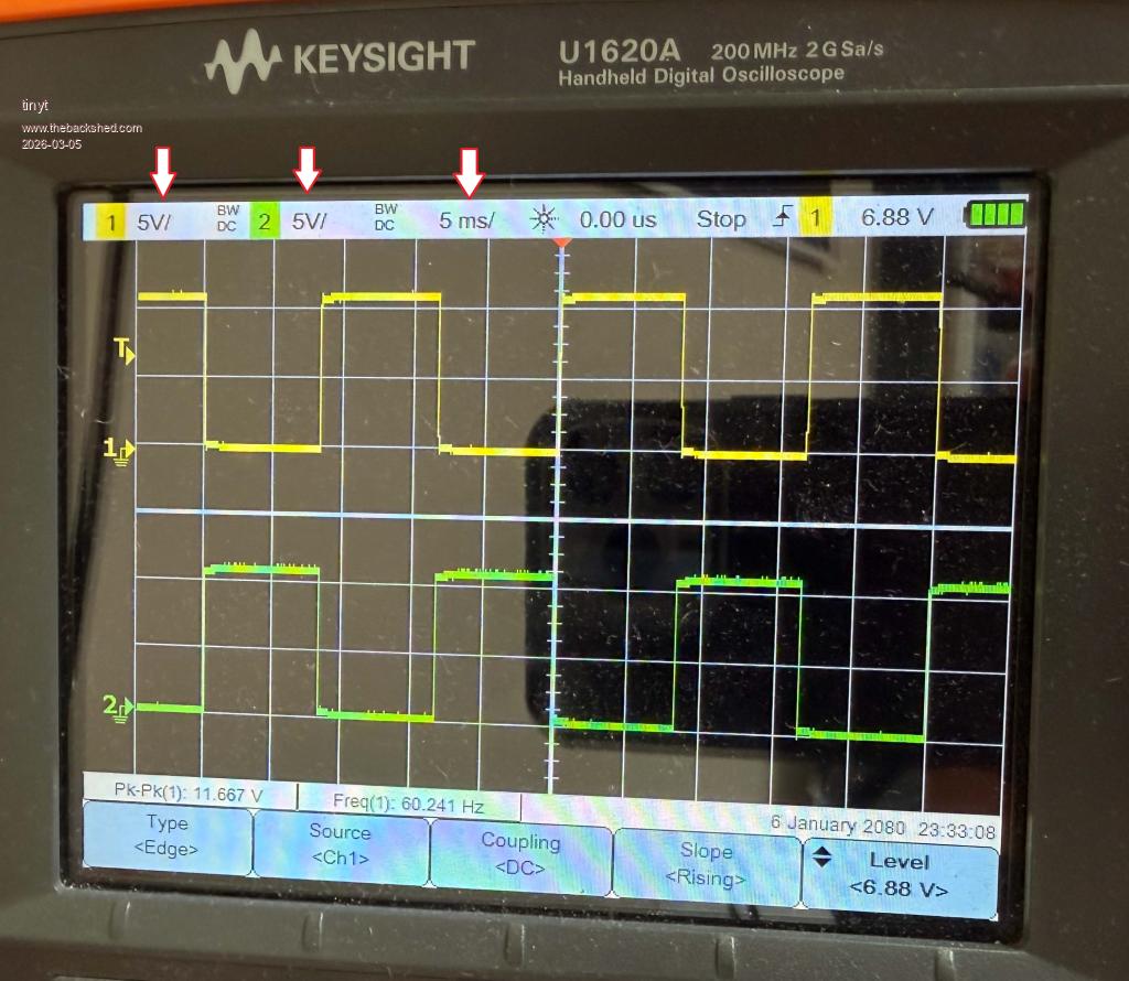 This is for L01(Yellow) and L02(Green) 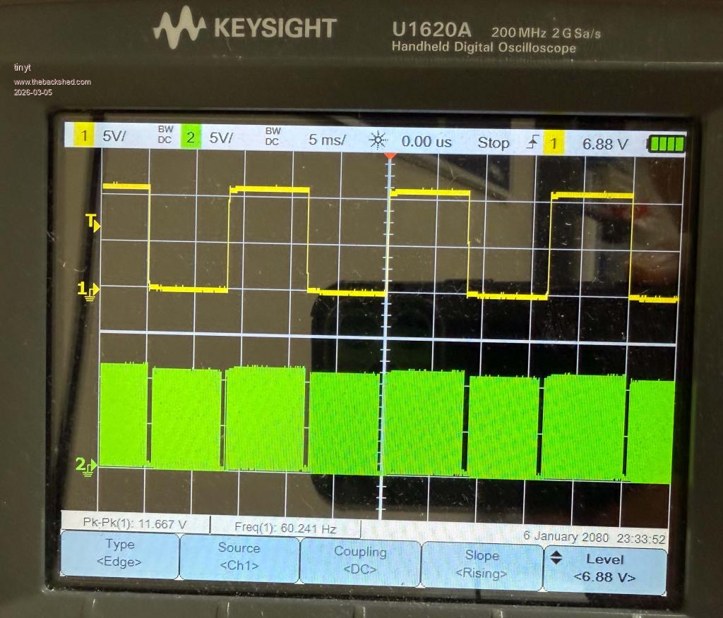 This is for L01(Yellow) and H02(Green) 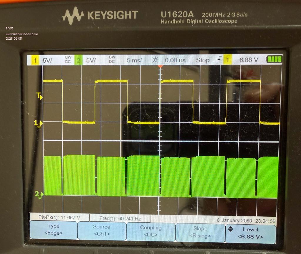 Edited 2026-03-05 01:45 by tinyt |
||||
| Bryan1 Guru Joined: 22/02/2006 Location: AustraliaPosts: 2138 |
Ok made up a ribbon cable and labelled each wire for identification and setup ch1 to LO1 and the ground for the probe to VS1 H02 and I left the ground off VS2 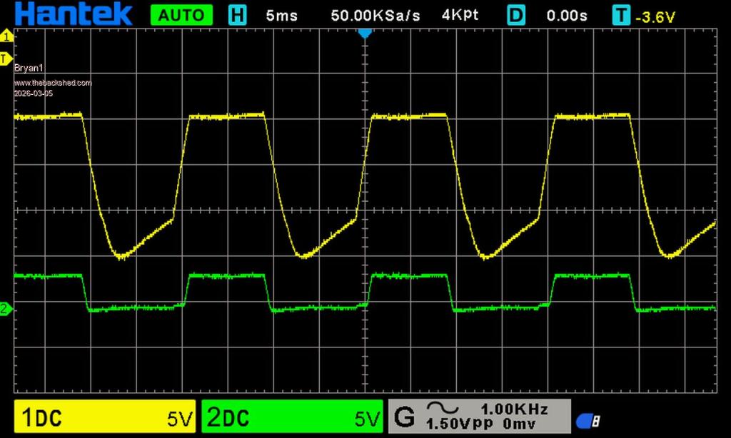 The next test was L01 and L02 and left VS1 and VS2 connected to the probe ground 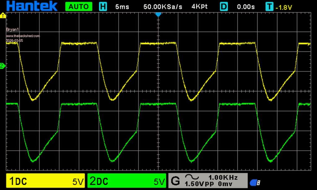 Now when I introduce the Gnd wire to the scope Gnd the wave form goes flat so me thinks something isn't right there. Now for this test I took the control board off and setup the programmable power supply for 15 volts where the current draw was 29mA Edited 2026-03-05 11:13 by Bryan1 |
||||
| tinyt Guru Joined: 12/11/2017 Location: United StatesPosts: 561 |
Still on the controller board powered and on switch to on: Use only the ch1 probe and touch its tip to pin 1 of U1 '2184, capture the scope screen and post. Then touch ch1 probe tip to pin1 of U2 '2184, capture the scope screen and post. See below where the red arrows are pointing for reference. Edit: Careful, do not touch probe tip to multiple pins on the '2184. Edit2: I have to study updated previous post. 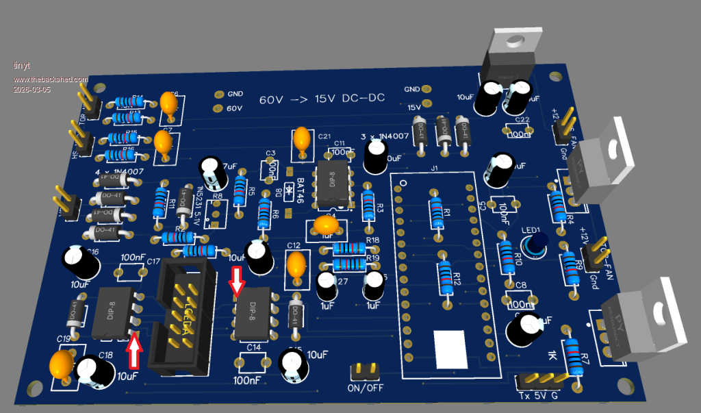 Edited 2026-03-05 11:21 by tinyt |
||||
| tinyt Guru Joined: 12/11/2017 Location: United StatesPosts: 561 |
Can you show pictures of your ribbon cable, where your ch1 tip and ground are connected and where your ch2 tip and ground are connected? Edit: Show also how the ribbon cable connector is plugged to the controller board socket. Edited 2026-03-05 11:36 by tinyt |
||||
| Bryan1 Guru Joined: 22/02/2006 Location: AustraliaPosts: 2138 |
Well it is amazing what happens when one turns on the control board CH1 L01 Gnd VS1 CH2 L02 Gnd VS2 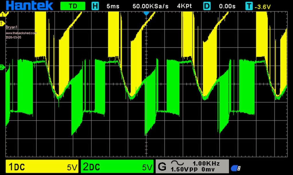 My setup for these tests 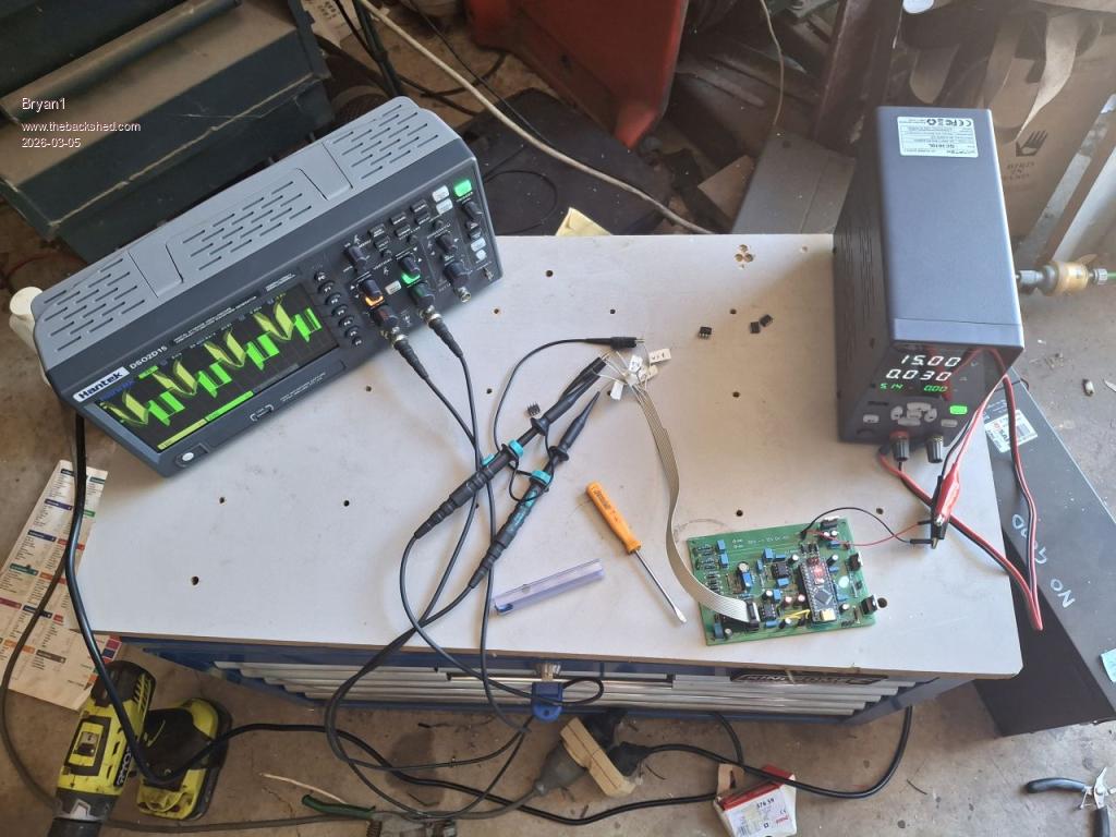 Now for that pin test Edited 2026-03-05 11:31 by Bryan1 |
||||
| tinyt Guru Joined: 12/11/2017 Location: United StatesPosts: 561 |
|
||||
| The Back Shed's forum code is written, and hosted, in Australia. | © JAQ Software 2026 |
