
|
|
Forum Index : Microcontroller and PC projects : Introducing the Colour Maximite 2
| Author | Message | ||||
| matherp Guru Joined: 11/12/2012 Location: United KingdomPosts: 11513 |
The schematic in the construction pack is correct and matches the PCBs made to the Gerbers - just checked UPDATE May be an issue with V1 will post more in a minute Edited 2020-05-23 22:57 by matherp |
||||
| matherp Guru Joined: 11/12/2012 Location: United KingdomPosts: 11513 |
The V1 schematic is incorrect. Unfortunately Geoff had to re-draw my DesignSpark schematic to make it acceptable for the magazine and the order of the DAC signal lines have been reversed in the manual transcription Correct, if illegible, schematic attached Motherboard - Project.pdf Edited 2020-05-23 23:13 by matherp |
||||
| Geoffg Guru Joined: 06/06/2011 Location: AustraliaPosts: 3362 |
I have updated the schematic in the construction pack (http://geoffg.net/Downloads/Maximite/CMM2_Construction_Pack.zip) to correct this error. The correct schematic is now Ver 2. Geoff Geoff Graham - http://geoffg.net |
||||
| SWA-Guy Newbie Joined: 01/02/2019 Location: GermanyPosts: 24 |
Hello Peter, thanks for fast feedback. I rewired the VGA-signal just like in your schematic. Now I have fantastic coloured screen. Another point I found, is the numbering of the USB-Host Type A for the keyboard. Attached the numbering I found in the internet. It is different from your schematics as well as in Geoffs. 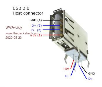 |
||||
| matherp Guru Joined: 11/12/2012 Location: United KingdomPosts: 11513 |
The pin numbering is totally arbitrary and depends who drew up the schematic. Mine is the one that was provided by DesignSpark who happened to label the GND pin as pin-1 and then move forward. Try the demo I just posted  |
||||
| SWA-Guy Newbie Joined: 01/02/2019 Location: GermanyPosts: 24 |
You are right, but if you (or me) use the schematic for your own testboard, you wire the connectors as shown in the schematic. And when then the numbering is not the same as in the standards declared you have problem. Just like here the keyboard would not work. Sorry about my know-it-all instruction, but I'm an electrical engineer and deal with these things every day. But nevertheless you and geoff do a fantastic job. |
||||
| matherp Guru Joined: 11/12/2012 Location: United KingdomPosts: 11513 |
Trace commands fixed in V5.05.02RC38 http://geoffg.net/Downloads/Maximite/Colour_Maximite_2_MMBasic.zip Edited 2020-05-24 07:34 by matherp |
||||
| matherp Guru Joined: 11/12/2012 Location: United KingdomPosts: 11513 |
V5.05.02RC39 Fix to bug loading CMM1 compatible sprite files when in 12 or 16-bit colour modes. Needed to run the example in the graphics example thread. NB: full change log is in the readme file http://geoffg.net/Downloads/Maximite/Colour_Maximite_2_MMBasic.zip |
||||
| SWA-Guy Newbie Joined: 01/02/2019 Location: GermanyPosts: 24 |
Hello Guys, today I played a little bit with my color maximite 2 test system. 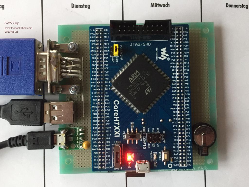 I noticed two things: 1. The core temperature goes up to 53�C with a current of 220mA for the complete system. The current for only the single Waveshare-board without my selfmade board is 210mA. Is this correct? In the beginning I read anywhere that the current should be ~145mA. I have two Waveshare-board, both have the same current. 2. If I use this little program to read the CPU-Temperature: CLS Do TEMP1 = Pin("Temp") Text 10, 100, "CPU-Temp: "+Left$(STR$(Temp1), 5) Loop I can't stop the program with "CRTL-C". Only a reset brings me back to the edit-mode. How warm is your Color Maximite 2? |
||||
| matherp Guru Joined: 11/12/2012 Location: United KingdomPosts: 11513 |
Temp and current consumption are both normal Put a PAUSE 10 in the loop and Ctrl-C will work - I'll try and find out why it doesn't anyway - it should UPDATE I was using a very long ADC sampling time with massive oversampling and it was missing the USB keyboard polling interval. Ctrl-C worked in your example from a serial console but not from the USB keyboard. I've tested a fix and it will be in the next release Edited 2020-05-25 04:46 by matherp |
||||
| GregZone Senior Member Joined: 22/05/2020 Location: New ZealandPosts: 114 |
Hi all. First post. Congratulations to the team on a very interesting looking evolution of the Colour Maximite! :) As someone who started out in the late 70's, with his own home built 6800 & 6809 systems (and hand assembled machine code), I see the following as 3 key points that make the CMM2 quite an appealing retro fun & educational system: 1. The great old-school instant power-on / stand-alone system. 2. A more complete and capable retro colour graphics capability. 3. A nicely evolved high-level interpreted BASIC, which now appears capable of running as fast as optimised machine code on old-school 1Mhz 8-bit CPU systems (this is quite a significant feature!). After reading all threads and documentation, I just have a couple of intial questions (apologies if I missed the answers elsewhere): a. Although it uses 32-bit ARM Cortex-M7 core (ie. not a "retro" simple 8-bit CPU core), is there ability to code / run applications in it's native Assembly code (or an ability to call embedded Assembly routines)? Some of us just like the ability to do some coding at the bare metal level. :) Plus, this also has further educational coding potential. b. I couldn't find a changelog on the PCB revisions. I was just wondering what has changed in the current revison 2.1 PCB, versus the V2.0 PCB shown in the GizmoStore listing? Looking forward to the CMM2 taking off with a huge community following, especially with the upcoming Silicon Chip article exposure! |
||||
TassyJim Guru Joined: 07/08/2011 Location: AustraliaPosts: 6538 |
Welcome. To answer your queries as best I can Peter replied to a. a few pages back: The only difference between the PCB versions is V2.1 has provision for replacing the crystal on the Waveshare module with an oscillator module. This was done to help some video stability problems but since then, firmware changes have eliminated the video problems so the oscillator replacement is no longer required. I think there was also a change to the copper fill regions. Again, no practical difference. Jim Edited 2020-05-25 10:10 by TassyJim VK7JH MMedit |
||||
| GregZone Senior Member Joined: 22/05/2020 Location: New ZealandPosts: 114 |
Thanks @TassyJim. I was doing the planning to source all the parts to build my own, but I ended up ordering one from GizmoStore (I believe I got the 2nd to last one). Unfortunately JLC are only allowing DHL Express to NZ at the moment, so the PCB�s would�ve been about $45 to land. �Then, several of the other parts (eg. from RS) where minimum qty 5, making the ancillary parts around $90 (not including the Waveshare CoreH743I board, or the 2mm pitch headers). �Then to cap it off, I could only find the 2mm headers on eBay, and I�m still awaiting eBay & AliExpress orders that I placed way back in March! So the idea of building my own went out the window pretty fast. �Even if I�d had a bunch of other PCB�s that I needed to re-order (so as to amortise the DHL shipping cost), I would�ve still had the 2mm header unknown delay problem, and the min 5 qty parts to absorb. I'm still likely to want to build my own eventualy, but it appears it�ll be most cost effective to actually build a batch of 5. �Then, I guess I�d need to sell 4 in order to recover the multiple qty build costs. As always, every build project comes with it's challenges. :) Edited 2020-05-26 16:44 by GregZone |
||||
| WhiteWizzard Guru Joined: 05/04/2013 Location: United KingdomPosts: 2991 |
@GregZone (sorry if I'm double posting again - I have emailed Gizmo as having many problems posting from phone). Have you tried contacting Grogster? He is based in NZ and should certainly be able to source the necessary parts for you that you require for a self-build CMM2.  |
||||
| WhiteWizzard Guru Joined: 05/04/2013 Location: United KingdomPosts: 2991 |
@GregZone (sorry if I'm double posting again - I have emailed Gizmo as having many problems posting from phone). Have you tried contacting Grogster? He is based in NZ and should certainly be able to source the necessary parts for you that you require for a self-build CMM2. |
||||
| JohnS Guru Joined: 18/11/2011 Location: United KingdomPosts: 4335 |
It looks like you should be able to use any RPi. I've just started a thread about using dfu-util under Linux and it's in the raspbian repo so should work. John |
||||
| Decoy Senior Member Joined: 02/08/2019 Location: DenmarkPosts: 109 |
Well, I am out of the loop for a little while when I come back, the Maximite 2 has arrived. Crazy. I usually don't have problems with working with older hardware and systems, and I love retro-tech. However - I do enjoy that I can be into this (Maximite 2) from the start! I always felt late to the game with the Colour Maximite 1. I have a question that I hope is not dim-witted: It has not escaped my attention that the Maximite 2 has fewer I/O ports than the Maximite 1. I am a great fan of numerous I/O's, as such I am fan of the Arduino 2560. So, is it possible to use a port expander (like the MCP23017) with I2C in MMBasic? If so, should I expect any problems like delay etc.? Thanks a lot. I am so stoked for the Maximite 2! Nicholas Edited 2020-05-27 02:16 by Decoy |
||||
| matherp Guru Joined: 11/12/2012 Location: United KingdomPosts: 11513 |
Yes of course, the CMM2 has three I2C ports, two on the back connector and the Nunchuck connector is also I2C. Even easier and faster is to use one or more shift registers chained together on one of the SPI ports (74HC795) Edited 2020-05-27 02:21 by matherp |
||||
| Decoy Senior Member Joined: 02/08/2019 Location: DenmarkPosts: 109 |
matherp, thanks! So - the MMBasic manual will have the code for how to use a port expander or shift register? |
||||
| Decoy Senior Member Joined: 02/08/2019 Location: DenmarkPosts: 109 |
Just found it in the back of the user manual  |
||||
| The Back Shed's forum code is written, and hosted, in Australia. | © JAQ Software 2026 |
