
|
|
Forum Index : Microcontroller and PC projects : Introducing the Colour Maximite 2
| Author | Message | ||||
Grogster Admin Group Joined: 31/12/2012 Location: New ZealandPosts: 9066 |
I got asked the exact same question from my PCB house, but in MY case, I told them to plate-through the holes, as I expected all those points would have been ground. 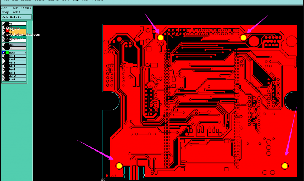 Does that mean I need to involve Mr. Dremmel and grind out the through-hole plating that is on my ones then, Peter? Smoke makes things work. When the smoke gets out, it stops! |
||||
| Sasquatch Senior Member Joined: 08/05/2020 Location: United StatesPosts: 296 |
I ordered CMM2 boards from JLCPCB, they didn't ask about plating the mounting holes. I should receive the boards in a few days so a good heads-up to check the mounting holes when they arrive. I can always drill them out if they are plated. Also a good suggestion to put fiber or plastic washers under the screw heads. I do see that on my MMX 144 boards the mounting holes ARE plated but on those boards there are no traces nearby so it makes no difference. -Carl -Carl |
||||
| Grogster Admin Group Joined: 31/12/2012 Location: New ZealandPosts: 9066 |
Hello.  Welcome to the forums. In my case, it was me ordering blank PCB's, NOT via JLC. JLC had no issues with the board gerbers at all. I was using PCB GoGo, which is my go-to PCB house for all my own boards. I will be using JLC for any and all of this design, because of the simplicity of ordering fully-assembled units. Well, as far as the top-copper is concerned anyway. Smoke makes things work. When the smoke gets out, it stops! |
||||
| matherp Guru Joined: 11/12/2012 Location: United KingdomPosts: 8592 |
JLC make the PCBs as per the gerbers with no plate-through on the mounting holes. |
||||
| CaptainBoing Guru Joined: 07/09/2016 Location: United KingdomPosts: 1985 |
I always do a sanity check on new batch of PCBs as a precaution (especially my own). Errors get marked with a dot of permanent marker (which washes off with meths). Simply bleeping the power rails would be enough to catch this... then comes the hunt �  Edited 2020-05-22 19:45 by CaptainBoing |
||||
| cTrix Newbie Joined: 04/05/2020 Location: AustraliaPosts: 16 |
My decision was just to leave that screw out! But I might fiber washer my screws all the same. I started looking at components to see if it was anything more than a power ground... but kinda expected it to be a track if it was carrying voltage. I wouldn't have expected it to be high! Glad I opted for unplated. My gut feeling was "why would you plate a case attachment hole anyway?" As someone who only purchased Mr. Dremmel for the first time last week, yes, you should certainly involve him. But also 3.3v > Digi GND. :-o You'd be screwed! (pun intended) Thanks Tom! Considering the stuff I've worked on for the Atari 2600, the CMM1 made perfect sense. It's like a super fast EGA machine without EHB. But I really needed EHB (I started porting an old EGA game I'd made when I was 12, but it wasn't looking good). Really looking forward to seeing what I can do with the CMM2. I'm making a more serious video about it - in particular the journey that is trying to build it without a kit. (spoiler alert, I'm building 5) Link: YouTube Colour MaxiMite 2 Intro Video � | � ctrix.net |
||||
| matherp Guru Joined: 11/12/2012 Location: United KingdomPosts: 8592 |
Just to be clear 3 of the mounting holes are completely isolated from any connection on both sides of the PCB. The one near pin39 of the I/O connector is connected to GND on both top and bottom. There is no problem if these holes are through plated. The only risk is if the screw head is big enough to bridge between the pad round any of the holes to other copper on the top AND if it is tightened with sufficient force to cut through the solder resist. |
||||
| thwill Guru Joined: 16/09/2019 Location: United KingdomPosts: 3848 |
EHB? Game*Mite, CMM2 Welcome Tape, Creaky old text adventures |
||||
| cTrix Newbie Joined: 04/05/2020 Location: AustraliaPosts: 16 |
This is great info. And massive thanks for your continued support on this project. It's been years since a piece of hardware has excited me this much. (The Minimig was last, the Gigatron a close second). I left my QBASIC days in the late 90s; and made far too many VB6 based tools - mainly because of the easy file access. I've always wished there was a fixed platform BASIC box - QB64 was just too "open sky" for me to take seriously - any by the time you hit 3D poly stuff you may as well use shadertoy and give it a C++ wrapper. This MMC2 box is it IMHO. Can't wait :-) (awaiting parts) Link: YouTube Colour MaxiMite 2 Intro Video � | � ctrix.net |
||||
| cTrix Newbie Joined: 04/05/2020 Location: AustraliaPosts: 16 |
EHB was "Extra Half Bright." �Otherwise known (IIRC) as RGBI. �It was Red + Green + Blue + Intensity. �The intensity was a brightens element that acted as a (from my memory) positive rail / negative rail on any given 1bit-RGB output. � Here is a MODE 7 (EGA) program I've quickly knocked up for ya.  You can see we've got the standard DAC ordering Blue / Green/ Cyan / Red / Megenta / Yellowish / White... but it's stepped down 25% (ish) and stepped up 25% (ish) either side. �This gave darker versions and brighter versions of the "DAC RGB Standards" where neither is too bold. �It was also used in the standard MSDOS text mode and incorporated into the first 16 colours of the QBASIC VGA standard. Apologies if this is slightly off topic to the CMM2. �Of course, one of the CMM2 allows palette customization - so one of the first things I'll be doing (if its' not standard in the 320x200 mode) is making a bunch of QBASIC back-compatable palette templates. Edited 2020-05-22 20:30 by cTrix Link: YouTube Colour MaxiMite 2 Intro Video � | � ctrix.net |
||||
| matherp Guru Joined: 11/12/2012 Location: United KingdomPosts: 8592 |
An new version V5.05.02RC36 is available for download at http://geoffg.net/Downloads/Maximite/Colour_Maximite_2_MMBasic.zip Changes: "Save As" in editor renamed "Backup" LS implemented as synonym for LIST FILES bug in pressing END twice in editor fixed keyboard buffer truncated when page scrolls in editor OPTION MODES command removed. Increased video stability in recent release makes this now redundant. IMPORTANT After loading the firmware execute Because the option list has changed in this release options will be corrupt. This will be avoided in future. |
||||
| thwill Guru Joined: 16/09/2019 Location: United KingdomPosts: 3848 |
Ausgezeichnet! Game*Mite, CMM2 Welcome Tape, Creaky old text adventures |
||||
| Poppy Guru Joined: 25/07/2019 Location: GermanyPosts: 486 |
In such cases of special importance you should ad a little note directly into the zip-file, so it cannot be missed by all others, probably not recognizing this particular posting! And by the amount of all postings some could easily get missed ...! Yeah, geiler Scheiss!  Andre ... such a GURU? Andre ... such a GURU? | ||||
| matherp Guru Joined: 11/12/2012 Location: United KingdomPosts: 8592 |
Good idea - done |
||||
| BrianP Senior Member Joined: 30/03/2017 Location: AustraliaPosts: 292 |
Don't overlook that you can get nylon bolts - nuts - washers hardware which is reasonably robust. No conduction issues there... B |
||||
| Grogster Admin Group Joined: 31/12/2012 Location: New ZealandPosts: 9066 |
I will leave my through-plated boards as they are then, and just use fibre-washers under the screw head to be sure. I only have ten of these boards, and if I order more blank ones(unlikely when it is so easy to get all the SMD done at JLC), I will make sure to say unplated if they ask. Smoke makes things work. When the smoke gets out, it stops! |
||||
| matherp Guru Joined: 11/12/2012 Location: United KingdomPosts: 8592 |
An new version V5.05.02RC37 is available for download at http://geoffg.net/Downloads/Maximite/Colour_Maximite_2_MMBasic.zip Changes: Fixes bug introduced in RC36 that stopped the enter key working in the filemanager and editor when using a USB keyboard Make OPTION LEGACY ON only available in a program and returns to normal when the program exits Edited 2020-05-23 21:14 by matherp |
||||
| SWA-Guy Newbie Joined: 01/02/2019 Location: GermanyPosts: 24 |
Unfortunate coincidences happen again and again: This morning I finished my Waveshare-testboard and started with release RC36, I was a little bit confued about the "edit" problem and looked for a wiring error. After a long while I change to RC35 and the editor works correct.  But I have an other problem with the VGA-colors. I found differences between the schematic V1 and PCB-Layout. In the PCB-Layout are the ports to the colour-signal turned. Is there a newer version of the schematic available ? Thanks |
||||
| Geoffg Guru Joined: 06/06/2011 Location: AustraliaPosts: 3165 |
I have updated the Colour Maximite 2 construction pack which you can download from: http://geoffg.net/Downloads/Maximite/CMM2_Construction_Pack.zip This includes parts list, PCB design files, firmware, etc. Updated is the schematic to include the Nunchuk connector, extra construction notes and Gerbers for the front/back panels if you would like a PCB fabrication house to make them (courtesy Peter M  ). ).Geoff Geoff Graham - http://geoffg.net |
||||
| Geoffg Guru Joined: 06/06/2011 Location: AustraliaPosts: 3165 |
Sorry, I don't understand. Could you be a bit more specific. Thanks, Geoff Geoff Graham - http://geoffg.net |
||||
