
|
|
Forum Index : Microcontroller and PC projects : Armmite - STM32H7: Developments
| Author | Message | ||||
goc30 Guru Joined: 12/04/2017 Location: FrancePosts: 435 |
ok ok i wait good idea for me, i like to have i2c/i2s connectors |
||||
| matherp Guru Joined: 11/12/2012 Location: United KingdomPosts: 11475 |
Please find attached V5.4.11 2018-06-17_020552_Armmite.zip 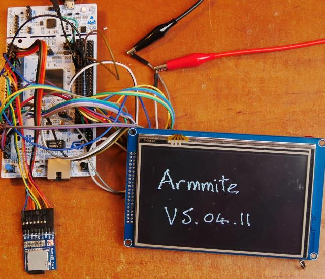 This release implements touch and 3 separate SPI channels. GUI functionality is tested and appears to work properly. VAR SAVE, VAR RESTORE and VAR CLEAR also now work. NB space available for save variables is 128Kbyte. OPTION BAUDRATE and OPTION PIN now also working. Pin usage is as follows: // SPI pin numbers SPI_INP_PIN 42 //PA6 SPI_OUT_PIN 43 //PA7 SPI_CLK_PIN 126// PG11 // SPI2 pin numbers SPI2_INP_PIN 28 //PA2 SPI2_OUT_PIN 27 //PC1 SPI2_CLK_PIN 69 //PB10 // SPI3 pin numbers SPI3_CLK_PIN 133 //PB3 SPI3_INP_PIN 134 //PB4 SPI3_OUT_PIN 48 //PB2 // TOUCH pin numbers TOUCH_CLK_PIN 19 //PF7 TOUCH_INP_PIN 20 //PF8 TOUCH_OUT_PIN 21 //PF9 Functionality is the same as the Micromite with the following exceptions: Three SPI channels SPI SPI2 SPI3 Normal syntax except that bit length can be anything from 4 to 32 (not just 8,16,32) Baudrate input is unlimited but the software will choose the best fit out of 256Kbs, 512Kbs, 1Mbs, 2Mbs, 4Mbs, 8Mbs, 16Mbs, 32Mbs The touch SPI channel is dedicated to touch and (later) SPI displays and does not impact the other SPI channels. All pins can be used for digital I/O when SPI and/or touch is not enabled I used "OPTION TOUCH 114,115" for the test ( PD0, PD1) Note the pin allocated to the SSD1963 RS pin has changed to pin 57 - RG1 |
||||
| matherp Guru Joined: 11/12/2012 Location: United KingdomPosts: 11475 |
Please find attached V5.4.12 This implements I2C and a RTC 2018-06-17_213858_Armmite.zip 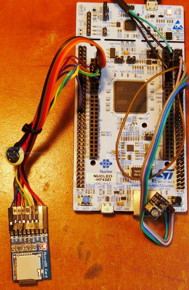 The RTC uses the STM32H7 internal RTC which is wired with a 32KHz crystal on the Nucleo PCB. As delivered the clock battery connection is direct to VCC. However, this can be disconnected by removing the zero ohm resistor at SB156 on the back of the board. Then connect a 3 volt battery between VBAT and GND. The VBAT pin is on the outer row near to the Arduino A3 pin. Connecting VBAT means that an external RTC chip is completely unnecessary. You can see in the picture the small battery I am using and the rough location of the connections.The software is written to automatically load the time from the clock when it powers up or is reset. The clock can be set using the normal. RTC SETTIME year, month, day, hour, minute, second {,day_of_week} Note the new optional "day_of_week" parameter this can be set between 1 and 7 for Monday to Sunday. The day of week can be interrogated with a new function "DAY$" this will return the one of "Monday","Tuesday","Wednesday","Thursday","Friday","Saturday","Sunday" as applicable. You can re-load the Micromite internal time from the RTC at any time by using RTC GETTIME I2C commands are as per the Micromite except that the I2C pins are dedicated and not available for other use Pins are (see picture for rough location) I2C_SCL 69 //PB10 I2C_SDA 70 //PB11 You should use the normal "I2C OPEN" command to set up the speed of the port and the timeout. NB valid speeds are limited to 100, 400, and 1000. Other speeds will be rejected. I've tested I2C with a BMP180 using the attached program which works perfectly without any change from running on the MM2. OPTION EXPLICIT OPTION DEFAULT FLOAT const i2caddr=&b1110111 const MS7=7 'set default wait period const signed=1 const unsigned=0 ' dim i2cin$ length 8 'max size for integer conversion dim UT%,UP% dim ac1%,ac2%,ac3,ac4%,ac5%,ac6%,b1%,b2%,mb%,mc%,md% 'bmp180 parameters dim x1%,x2%,b5%,b6%,x3,b3%,b4%,b7%,OSS% dim temperature%,pressure% DIM altitude,QNH,pressureinHpa dim OSSdata%(4) dim OSSscale%(4) I2C OPEN 400,1000 init: OSS%=1 'set oversampling ratio ' OSS%=0 ' Uncomment this line to check algorithm against datasheet OSSdata%(0)=&H34 'commands to sample pressure% with different levels of oversampling OSSdata%(1)=&H74 OSSdata%(2)=&Hb4 OSSdata%(3)=&HF4 OSSscale%(0)=1 'scale factors for calcs when oversampled OSSscale%(1)=2 OSSscale%(2)=4 OSSscale%(3)=8 ' I2C WRITE i2caddr,1,1,&HAA 'send read calibration data command I2C READ i2caddr,0,22,i2cin$() 'read in calibration data ac1%=intconv(mid$(i2cin$,1,2),signed) ac2%=intconv(mid$(i2cin$,3,2),signed) ac3=intconv(mid$(i2cin$,5,2),signed) ac4%=intconv(mid$(i2cin$,7,2),unsigned) ac5%=intconv(mid$(i2cin$,9,2),unsigned) ac6%=intconv(mid$(i2cin$,11,2),unsigned) b1%=intconv(mid$(i2cin$,13,2),signed) b2%=intconv(mid$(i2cin$,15,2),signed) mb%=intconv(mid$(i2cin$,17,2),signed) mc%=intconv(mid$(i2cin$,19,2),signed) md%=intconv(right$(i2cin$,2),signed) ' ' Uncomment this block to check algorithm against datasheet ' ' ac1%=408 ' ac2%=-72 ' AC3=-14383 ' ac4%=32741 ' ac5%=32757 ' ac6%=23153 ' b1%=6190 ' b2%=4 ' mb%=-32768 ' mc%=-8711 ' md%=2868 main: I2C WRITE i2caddr,0,2,&HF4,&H2E 'send temp conversion pause MS7 'wait for temperature% conversion I2C WRITE i2caddr,1,1,&HF6 'send read data I2C READ i2caddr,0,2,i2cin$() 'read 2 bytes UT%=intconv(i2cin$,unsigned) ' UT%=27898 ' Uncomment this line to check algorithm against datasheet I2C WRITE i2caddr,0,2,&HF4,ossdata%(oss%) 'send pressure% conversion pause (oss%+1)*ms7 'wait for the p ressure% conversion I2C WRITE i2caddr,1,1,&HF6 'send read data I2C READ i2caddr,0,3,i2cin$() 'read 3 bytes UP%=intconv(i2cin$,unsigned) UP%=UP%>>(8-oss%) 'scale the oUT%pUT% by the numb%er of unused bits in the xlsb byte ' UP%=23843' Uncomment this line to check algorithm against datasheet calc_temp calc_pressure pressureinHpa=pressure%/100 print "Temperature = ",str$(temperature%/10,4,1),"Deg C" print "Local pressure = ",str$(pressure%/100,4,1),"Hectopascal/mb" inpUT "QNH in Hpa/Mb ? ",QNH altitude=calcaltitude(QNH,pressureinHpa) print "Current altitude in feet = ",altitude print "Reverse calculate Sea level pressure = ",calcQNH(altitude,pressureinHpa),"Hectopascal/mb" end ' ' calc_temperature%: calculate the temperature% from the raw temperature% given the calibration parameters ' sub calc_temp: x1%=(UT%-ac6%)*ac5%\powerof2(15) x2%=mc%*powerof2(11)/(x1%+md%) 'This needs to be a floating divide to match the datasheet b5%=x1%+x2% temperature%=(b5%+8)\powerof2(4) end sub ' ' calc_pressure: calculate the pressure% from the raw pressure% given the calibration parameters and temperature% oUT%pUT% ' sub calc_pressure b6%=b5%-4000 x1%=(b2%*(b6%*b6%/powerof2(12)))\powerof2(11) x2%=ac2%*b6%\powerof2(11) x3=x1%+x2% b3%=(((ac1%*4+x3)*ossscale%(oss%))+2)\4 x1%=AC3*b6%\POWEROF2(13) x2%=(b1%*(b6%*b6%/POWEROF2(12)))\POWEROF2(16) x3=((x1%+x2%)+2)\4 b4%=ac4%*(abs(x3+32768))\powerof2(15) b7%=abs(UP%-b3%)*(50000\ossscale%(oss%)) pressure%=(b7%*2)\b4% x1%=(pressure%\powerof2(8))*(pressure%\powerof2(8)) x1%=(x1%*3038)\powerof2(16) x2%=(-7357*pressure%)\powerof2(16) pressure%=pressure%+(x1%+x2%+3791)\powerof2(4) end sub ' FUNCTION calcQNH(currentaltitude,localpressure) calcQNH=(localpressure*100)/((1-(currentaltitude*0.3048/44330))^5.255)/100 end function ' function log10(x) log10=log(x)/2.302585093 end function ' function calcaltitude(sealevelpressure, localpressure) local a as float, b as float calcaltitude=((10^(log10(localpressure/sealevelpressure)/5.2558797))-1)/-6.8755856 *1000000 end function Function intconv(s$, p%) as integer local integer l,k,j,i=len(s$) k=peek(varaddr j) for l=1 to i poke byte k+i-l,asc(mid$(s$,l,1)) next l if p% then if (asc(left$(s$,1)) and &H80) then for l=i to 7 poke byte k+l,&HFF next l endif endif intconv=j End Function ' Function powerof2(i as integer) as integer powerof2=(1<<i) End Function |
||||
| matherp Guru Joined: 11/12/2012 Location: United KingdomPosts: 11475 |
Please find attached V5.4.13 2018-06-20_193606_Armmite.zip This implements ILI9341, ILI9481, ST7735, ILI9163, ILI9431-parallel and user Basic displays. MMX sprite functionality is fully implemented. See the video for my example program running. See the MMX manual for details of the commands. ILI9481, ILI9341, ILI9341_16 and SSD1963_4_16 are now implemented using an in-memory buffer which does not affect the 498K available for the user. This allows all sprite, blit and transparent text functionality to work on these displays extremely efficiently. An additional option is implemented OPTION FLASHPAGES n n can be between 1 and 4. This sets the number of 128K segments of flash available for the user program. Default is 4 (512K) but reducing this improves speed for loading programs and executing NEW commands. With FLASHPAGES set to 1 the MEMORY command will show 256K (128K for the program and 128K for saved variable usage) 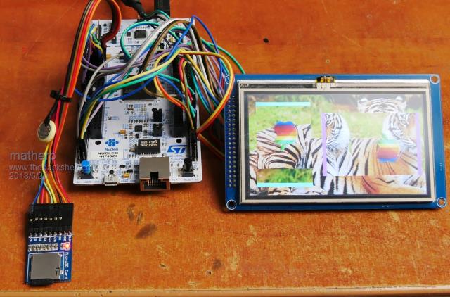 Demo code: 2018-06-20_192320_apple.zip option explicit option default none const leftbar = 1, rightbar = 2, topbar=3, bottombar=4, rightapple=5, leftapple=6 dim integer moveright=1, movedown=1 box 200,50,10,172,,rgb(magenta),rgb(magenta) box 20,20,150,10,,rgb(cyan),rgb(cyan) blit read leftbar,200,50,10,172 sprite copy leftbar, rightbar, 1 'make one copy blit read topbar,20,20,150,10 sprite copy topbar, bottombar, 1 'make one copy load sprite rightapple,"apple" sprite copy rightapple,leftapple,1 'make one copy load image "tiger480" sprite interrupt collision blit show rightapple,250,100,0 blit show leftapple,50,100,0,2 blit show leftbar,199,50,1 blit show rightbar,460,50,1 blit SHOW topbar,20,20,2 blit SHOW bottombar,20,240,2 do if moveright then sprite scrollr 199,50,262,172,5,0 else sprite scrollr 199,50,262,172,-5,0 endif if movedown then sprite scrollr 20,19,150,222,0,-5 else sprite scrollr 20,19,150,222,0,5 endif loop ' ' sub collision local integer i, c(10), j if sprite(S) = 0 then 'collisions caused by scroll j=sprite(c,0) for i=1 to j 'store the collisions because a clearing scroll move will clear them from the list c(i)=sprite(C,0,i) next i for i=1 to j 'now process them process_collision(c(j)) next i endif end sub ' get details of the specific collisions for a given sprite sub process_collision(S as integer) select case S case leftbar sprite scrollr 199,50,262,172,5,0 'make a move to clear the collision sprite show rightapple,sprite(x,rightapple),sprite(y,rightapple),0,0 'mirror the sprite moveright=1 case rightbar sprite scrollr 199,50,262,172,-5,0 'make a move to clear the collision sprite show rightapple,sprite(x,rightapple),sprite(y,rightapple),0,1 'mirror the sprite moveright=0 case topbar sprite scrollr 20,19,150,222,0,-5 'make a move to clear the collision sprite show leftapple,sprite(x,leftapple),sprite(y,leftapple),0,3 'invert the sprite movedown=1 case bottombar sprite scrollr 20,19,150,222,0,5 'make a move to clear the collision sprite show leftapple,sprite(x,leftapple),sprite(y,leftapple),0,0 'invert the sprite movedown=0 case else end select end sub |
||||
| matherp Guru Joined: 11/12/2012 Location: United KingdomPosts: 11475 |
One more release today (good progress  ) 5.04.14 but don't miss details of 5.04.13 on page 2 of the thread. ) 5.04.14 but don't miss details of 5.04.13 on page 2 of the thread.2018-06-21_044222_Armmite.zip This includes serial port support. There are 4 H/W serial ports (in addition to the console) with full H/W interrupt support. All functionality is implemented as per the MM+ with the exception of RS485 support (to come later). By default the RX pins are pulled high but this can be disabled with: OPTION SERIAL PULLUP DISABLE and re-enabled with: OPTION SERIAL PULLUP ENABLE pins are: COM1_TX_PIN 101 //PA9 COM1_RX_PIN 76 //PB15 COM2_TX_PIN 36 //PA2 COM2_RX_PIN 37 //PA3 COM3_TX_PIN 136 //PB6 COM3_RX_PIN 73 //PB12 COM4_TX_PIN 110 //PA15 COM4_RX_PIN 18 //PF6 This just leaves PWM and analogue input to code and the STM32 will be close to the MMX in functionality. |
||||
| goc30 Guru Joined: 12/04/2017 Location: FrancePosts: 435 |
Very very GOOD JOB!! I don't understand STM Nucleo logic For com1, they have not connected pins with D0/D1 Arduino who is used as "hardware serial" in many shields |
||||
| matherp Guru Joined: 11/12/2012 Location: United KingdomPosts: 11475 |
That is my allocation - I'll change it so COM4 is on those pins. I'll also change I2C so it is on the normal Arduino pins - watch this space  |
||||
| goc30 Guru Joined: 12/04/2017 Location: FrancePosts: 435 |
No, you have good idea to use this pins, I have think that STM connect d0/d1 on UART1 rx/tx but no, they are connected on signals PG6/PG14 as USART6 (and also SPI1  ) ) |
||||
| matherp Guru Joined: 11/12/2012 Location: United KingdomPosts: 11475 |
Please find attached V5.04.15 2018-06-22_173716_Armmite.zip This has some pin changes as follows (puts com4 and I2C onto the Arduino header): COM1_TX_PIN 101 //PA9 USART1 COM1_RX_PIN 76 //PB15 COM2_TX_PIN 36 //PA2 USART2 COM2_RX_PIN 37 //PA3 COM2_EN_PIN 118 //PD4 COM3_TX_PIN 136 //PB6 UART5 COM3_RX_PIN 73 //PB12 COM4_TX_PIN 129 //PG14 USART6 COM4_RX_PIN 124 //PG9 I2C_SCL 139 //PB8 I2C_SDA 140 //PB9 Note that COM2 now supports an enable pin (active high) for driving RS485 transceivers. This is enable by adding "DE" to the open command - see example below: There are also changes to the other parameters for opening serial ports. "9BIT" is no longer valid - do not use "ODD" adds an odd parity bit (making 9 bits if normal 8-bit data is sent) "EVEN" adds an even parity bit (making 9 bits if normal 8-bit data is sent) "7BIT" reduces the data to seven bits (total of eight if parity is specified) other parameters (INV, S2, OC) are as the MM manual In addition you can now specify a transmit completion interrupt as well as a receive interrupt. This works on any of the 4 com ports - see the example. This example outputs a "proper" modbus RTU message (8 data bits + even parity) 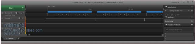 Open "com2:9600, 1024, myrxint, 256, mytxint, de, even" As #1 For i=2220 To 2400 Print #1,Str$(i,4)+" "; Next i Print #1,"" Do Loop Until k=1 close #1 end Sub myrxint End Sub Sub mytxint Print "TXcomplete" k=1 End Sub |
||||
| goc30 Guru Joined: 12/04/2017 Location: FrancePosts: 435 |
yesss!! 1000 thanks peter  here pinouts excel sheet with signals names 2018-06-22_191039_NUCLEO-H743ZI-pinout2.zip I can translate my modbus/gps app on this card |
||||
| matherp Guru Joined: 11/12/2012 Location: United KingdomPosts: 11475 |
Please find attached V5.04.16 2018-06-22_223239_Armmite.zip This has LONGSTRING, JSON, and background GPS functionality as per the MMX (see MMX manual for details). In addition RTC SETTIME is removed. Setting the STM32 RTC is done by setting TIME$ and DATE$. the day of the week is automatically calculated for the date and will always be available once DATE$ is set by using the DAY$ function. If the battery backup to the STM32 RTC is connected (remove SB156 first) then the time and date will be correct immediately on power up. |
||||
TassyJim Guru Joined: 07/08/2011 Location: AustraliaPosts: 6536 |
I have successfully run the SSD1306 Basic Driver. There were only a few minor changes to Peters original code. I used FONT 1 instead of a loaded font and changed the syntax of the ON ERROR SKIP lines. 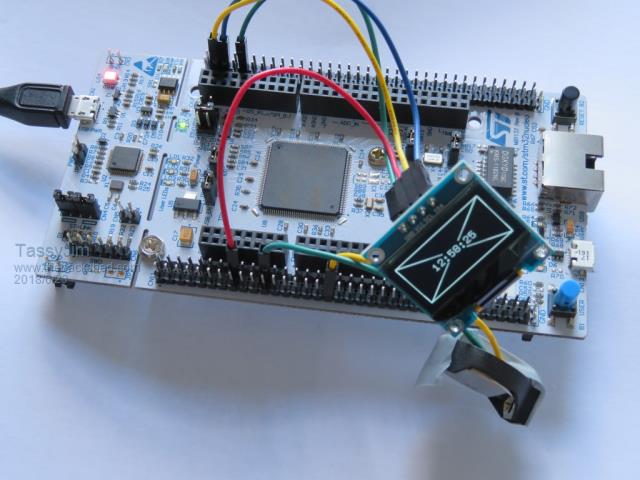 Together with the RTC, I now have another clock. I might try a bigger display next. Jim VK7JH MMedit |
||||
| TassyJim Guru Joined: 07/08/2011 Location: AustraliaPosts: 6536 |
I have added a sheet for the Arduino connector pinouts. 2018-06-23_160355_NUCLEO-H743ZI-pinout3.zip I have also changed all pages to refer to the CPU sheet for the pin notes. This way you only have to update the one sheet and the changes should reflect on the other sheets. I left the original sheets intact in case I have made too many mistakes. Jim VK7JH MMedit |
||||
| TassyJim Guru Joined: 07/08/2011 Location: AustraliaPosts: 6536 |
OPTION LCDPANEL USER is not listed under OPTION LIST and it is not saved over restarts > OPTION LCDPANEL USER, 128,64 > option list OPTION FLASHPAGES 1 OPTION COLOURCODE ON > VK7JH MMedit |
||||
| matherp Guru Joined: 11/12/2012 Location: United KingdomPosts: 11475 |
Please find attached V5.04.17 2018-06-24_043816_Armmite.zip This implements loadable fonts (and possibly Cfunctions if I knew how to compile them for the H7  ). It also fixes the reporting of OPTION LCDPANEL USER ). It also fixes the reporting of OPTION LCDPANEL USERThis is deliberate and I think the same on the whole MM range. This is because bad things could happen if the Basic routines were not loaded when the MM restarts. The SSD1306 driver program example now works without any changes |
||||
| TassyJim Guru Joined: 07/08/2011 Location: AustraliaPosts: 6536 |
Thanks Peter, that works better now. VK7JH MMedit |
||||
| panky Guru Joined: 02/10/2012 Location: AustraliaPosts: 1127 |
Jim, I would like to join the fun and assist with testing. Can you provide details of the part number and source for the Nucleo board and also details of software and procedures for updating the Nucleo that you are using to test each new version that Peter is producing. Looks a really fascinating project. For Peter, have you looked at what would be involved in porting to any of the lower cost, lower performance STM32 chips? Just curious, especially in regard to your statement re the ease of development compared to the PIC32 chips. regards, panky ... almost all of the Maximites, the MicromMites, the MM Extremes, the ArmMites, the PicoMite and loving it! |
||||
| isochronic Guru Joined: 21/01/2012 Location: AustraliaPosts: 689 |
Looks pretty impressive. One example board I recently saw - interesting small M4 - another of the hundreds in the genre I guess. |
||||
| TassyJim Guru Joined: 07/08/2011 Location: AustraliaPosts: 6536 |
Start by reading this thread https://www.thebackshed.com/forum/forum_posts.asp?TID=10397&PN=3&TPN=2 I bought mine from element14 http://au.element14.com/stmicroelectronics/nucleo-h743zi/dev-board-nucleo-144-cortex-m7/dp/2776646 They are out of stock but RS also stock them. The main requirement to look for is "NUCLEO-H743ZI" and 144 pin. You will have to provide some headers. 4 rows of 36. For programming I use Peter's suggestion: All I had to do was install "STM32CubeProgrammer" plug in the Nucleo board. Ignore any Windows request about what to do with it. Fire up STM32CubeProgrammer Click on "Connect". I only have one device so no need to choose the correct one. Click on the second green icon on the left side (Arrow pointing to brick) I suggest doing a full erase. then browse for the file. I use the *.elf ones Peter provides. Select Verify. Click on program. With verify, the process takes 10 seconds. Click on disconnect. close STM32CubeProgrammer Point MMEdit or Teraterm at the com port which Windows created without any help form me. After a firmware update, I should do a power cycle but I find that pressing the reset button a couple of times is sufficient to give me MMBasic prompt. All-in-all, about a zillion times faster than Microchip chips. I will take a few screenshots next time I do a program and post them here. Jim VK7JH MMedit |
||||
| TassyJim Guru Joined: 07/08/2011 Location: AustraliaPosts: 6536 |
Simple programming guide with pictures. 2018-06-24_144517_Programming_Nucleo.zip Jim VK7JH MMedit |
||||
| The Back Shed's forum code is written, and hosted, in Australia. | © JAQ Software 2026 |
