
|
|
Forum Index : Microcontroller and PC projects : Picomite VGA and Python
| Author | Message | ||||
| Tinine Guru Joined: 30/03/2016 Location: United KingdomPosts: 1646 |
Meh...steppers are dumb...literally Better if @Volhout figured out the PIO quadrature decode and then the Pico can do proper motor control  Then we show those hack-a-wotnot clowns what MMBasic can do  Craig |
||||
| Rickard5 Guru Joined: 31/03/2022 Location: United StatesPosts: 463 |
Only thing about Python Is I've seen some sample code and setups to "Barrow" from smarter PEOPLE FIRST THANKS Mick if we look at the Diagram Mick found, the First working Module I'm hoping to plug in to the GPIO port and have 3 or 4 drivers each step and Dir to a gpio pin the Grayed out MS Pins I'd like to see go to Header pins to provide Logic hi and low to configure micro stepping. pins 1A,1B and 2A,2B out to Screw Terminals for the stepper, and Screw terminals to access the free pins not used by the steppers The eventual goal is to integrate a Pico on board with the steppers and make my Goofy serial Pico cluster idea work with pico onboard modules acting as I/O slaves to a Master Controller PMVGA or CMM2 Latter I'd like to do the same thing with servos and FET Switches too 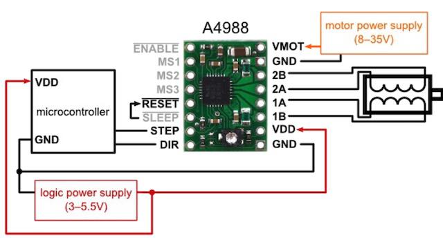 I may be Vulgar, but , while I'm poor, I'm Industrious, Honest, and trustworthy! I Know my Place |
||||
| Rickard5 Guru Joined: 31/03/2022 Location: United StatesPosts: 463 |
NO NO NEVER This Module is a Major Life Goal in my Maker Lego Set, Plus Organic discussion builds new Ideas and expanded knowledge I may be Vulgar, but , while I'm poor, I'm Industrious, Honest, and trustworthy! I Know my Place |
||||
| Mixtel90 Guru Joined: 05/10/2019 Location: United KingdomPosts: 8913 |
It may be that all you need to do is something like this GPdir = direction FOR i = number_of_pulses PULSE GPstep, pulse_width pause pulse_width NEXT I may be wrong, I've not read the stuff. Mick Zilog Inside! nascom.info for Nascom & Gemini Preliminary MMBasic docs & my PCB designs |
||||
| DaveJacko Senior Member Joined: 25/07/2019 Location: United KingdomPosts: 103 |
You might be interested in my project.. drives 2 StepSticks at independent speeds with a Micromite, bit-banged, so would easy scale up to many more, depends how fast you want to go. program is simple, although it does not ramp up to speed. will post code if anyone likes.. have a look at my brief video.. https://youtu.be/Buybf25-wbg Try swapping 2 and 3 over |
||||
| lizby Guru Joined: 17/05/2016 Location: United StatesPosts: 3790 |
Nice. Is that a servo doing up pin and down pin? Please do post your code, and anything you have about the mechanics. PicoMite, Armmite F4, SensorKits, MMBasic Hardware, Games, etc. on FOTS |
||||
| Rickard5 Guru Joined: 31/03/2022 Location: United StatesPosts: 463 |
That is Cool Dave, I would love to see the code for that it would be a cool thing to port to the Pico I may be Vulgar, but , while I'm poor, I'm Industrious, Honest, and trustworthy! I Know my Place |
||||
| lizby Guru Joined: 17/05/2016 Location: United StatesPosts: 3790 |
I've played with your A4988 module. Here is a daughter board which would plug into or solder on a board I already have that breaks out 8 I/Os plus 3V3 & 0V--that's the 10-pin header on the left: 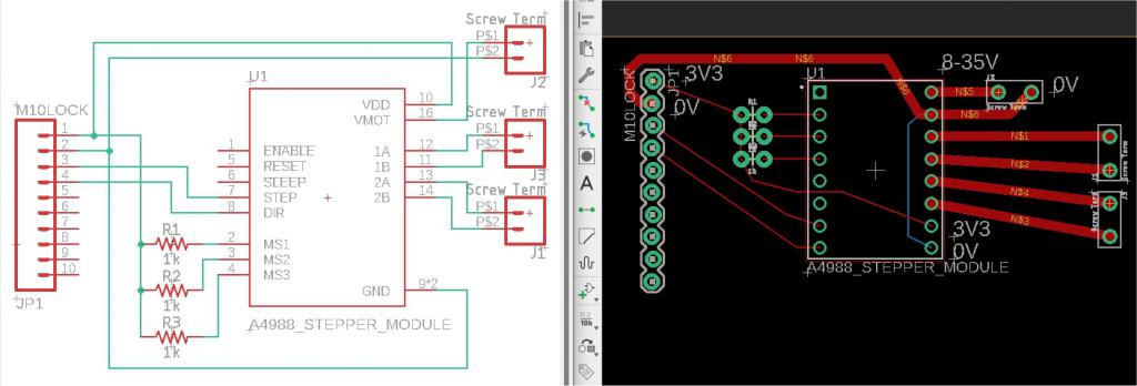 If you like it, 3 more A4988 modules can be added below. There are pads for 3 optional pullup resistors to adjust the resolution of the steps. Anybody else--please point out errors or omissions. ~ Edited 2022-07-15 05:34 by lizby PicoMite, Armmite F4, SensorKits, MMBasic Hardware, Games, etc. on FOTS |
||||
| circuit Guru Joined: 10/01/2016 Location: United KingdomPosts: 305 |
I too would be VERY much delighted to see your code. |
||||
| Rickard5 Guru Joined: 31/03/2022 Location: United StatesPosts: 463 |
Not to be too demanding but the pull-up resistors are SUPER GREAT, but could they be Switched or Jumpered to Switched with the likes of 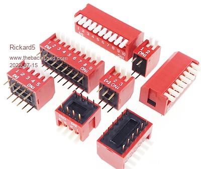 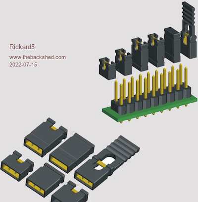 total of 3 Steppers should be OK per Pico, but it would be more Gooder if we could breakout any free pins to screw terminals for things like end stop switches and rotary encoders or even IR Pairs, stuff like that BUT That is way too GOODER Thanks Lizby I may be Vulgar, but , while I'm poor, I'm Industrious, Honest, and trustworthy! I Know my Place |
||||
| lizby Guru Joined: 17/05/2016 Location: United StatesPosts: 3790 |
Rick--If I understand the way it works, I could put a single inline resistor in the lead from 3V3 to what I had as 3 resistors, replace those pads with a 3x2 header, and the shorting plugs would work. The PCB I have has plenty of pins broken out. If this proof of concept works, I can make a single PCB instead of having this as a daughter board. (You're not intending for this to be a VGA PCB are you? Otherwise, looks OK to you? I'll wait until tomorrow to add additional A4988 modules to see if anyone else has comments. What's the least expensive motor I can buy from Aliex to test this? I already have the modules in my cart at about a dollar each. I'd rather not spend $15 including shipping if there's a cheaper motor it can be tested with. PicoMite, Armmite F4, SensorKits, MMBasic Hardware, Games, etc. on FOTS |
||||
| Rickard5 Guru Joined: 31/03/2022 Location: United StatesPosts: 463 |
Yes that should work, so you set micro stepping depending on the Project of the day I know I'm asking for the world and all but it would be nice to keep the VGA SD Card, and KB pins open in that order of rubbing the Genie's lamp. (example End Project would be to drive a Leadscrew on a Drill Press, and have the VGA Display attached to Drill Press like a Digital Readout. The SD Card would be nice just for loading and saving programs. and if the KB could be added then so much the better to have 88 more input Switches and a full self contained Dev Environment :) but those are just wishes that can be planned for and built with daughter boards, but it's easier to wish for the whole thing and cut down features than add features unexpectedly :) Looks like a winner :) thanks for working on this with me :) and take all the time you no Rush I've been waiting since 1976 for something like this :) I can hold out until the Tricentennial LOL :) Pretty much just recycle steppers from Floppy drives or DVD / CDROMS if you need more powerful ones I can send you some along :) This Video will give you the idea I may be Vulgar, but , while I'm poor, I'm Industrious, Honest, and trustworthy! I Know my Place |
||||
| lizby Guru Joined: 17/05/2016 Location: United StatesPosts: 3790 |
Rick--I know Mick's VGA boards have SD card and keyboard, but I haven't paid enough attention to know if 8 extra I/O lines are available. SPI LCD is also an option, and the SPI pins are already available because of the SD card. Would VGA display be better on a drill press than LCD? Re motors, I haven't had a floppy disk drive in about 20 years. I'll ask the local PC repair guy if he has any lying about. PicoMite, Armmite F4, SensorKits, MMBasic Hardware, Games, etc. on FOTS |
||||
| Rickard5 Guru Joined: 31/03/2022 Location: United StatesPosts: 463 |
Lizby My big thing with VGA is bigger more readable and FREE screens that would also give you the opportunity to have an editor so terminal requirement and VGA Monitors are FREE by the Dump Load. I could live with out SD Cards Easy if we need the pins but like I say SD Card is a nicety as to motors don't forget DVD and CDROMS Rick I may be Vulgar, but , while I'm poor, I'm Industrious, Honest, and trustworthy! I Know my Place |
||||
| Mixtel90 Guru Joined: 05/10/2019 Location: United KingdomPosts: 8913 |
Coming up very soon now - PicoMite LEO Maxi 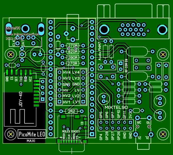 If you only wanted it for this project you could leave off the JDY-40, all the audio stuff and the linear regulator. This is a baby board - 72x54mm - there's no case. You'd probably have to either have the SDcard internal or 3D print one to fit. Alternatively, I could soon do something based on this, with the clever bits removed and , if I can route the traces, do a bigger GPIO connector that includes the extra five pins. I can't do a lot with the JDY-40 side, but the other side can be mostly spare space once all the audio stuff is gone. Using a SSD1963 would be nice, but they are quite expensive to have near a drill and you don't get many spare pins when they are driven from a PicoMite. Mick Zilog Inside! nascom.info for Nascom & Gemini Preliminary MMBasic docs & my PCB designs |
||||
| Volhout Guru Joined: 05/03/2018 Location: NetherlandsPosts: 5953 |
@Mick, Would it be an idea to make 1 thread in which you put all your board designs Mick ? This is Leo Maxi, but I can't remember where Leo was, and it was also called a different name before right ? Simply 1 thread with the designs, and links to the (when available) gerbers or construction packs. Regards, Volhout PicomiteVGA PETSCII ROBOTS |
||||
| Mixtel90 Guru Joined: 05/10/2019 Location: United KingdomPosts: 8913 |
Actually, I was considering just that. You aren't the only one that loses track. lol I might put them on my Dropbox link too. I need to get round to sorting them all out. Details for this one *won't* appear here, this info is just for guidance and the board isn't quite ready yet. It'll be on the LEO thread. Mick Zilog Inside! nascom.info for Nascom & Gemini Preliminary MMBasic docs & my PCB designs |
||||
| lizby Guru Joined: 17/05/2016 Location: United StatesPosts: 3790 |
+1. Or in your signature. Or on a fruitoftheshed page. PicoMite, Armmite F4, SensorKits, MMBasic Hardware, Games, etc. on FOTS |
||||
| lizby Guru Joined: 17/05/2016 Location: United StatesPosts: 3790 |
Ok, Rick, I just ordered these from JLCPCB:  Slow boat shipping (which is about 14-20 days now, about back to pre-pandemic times) for 5: $6.38 with PayPal. Even if it's wrong, it shouldn't be too hard to fix it with wires and then remix. I can mail you some when they arrive, or I can post the gerbers and you can order your own (I'll mail you the picomite board that this would plug into). Lance Edited 2022-07-16 01:00 by lizby PicoMite, Armmite F4, SensorKits, MMBasic Hardware, Games, etc. on FOTS |
||||
| Rickard5 Guru Joined: 31/03/2022 Location: United StatesPosts: 463 |
MICK That is a Thing of Beauty and a Joy forever but for my Purposes I would like to see just a header for the SD Card as I have been playing with the example circuit and just 1 of the 100's of micro SD adapters I got in my junk box and I can integrate that in to my case no need to waste the board space! same thing with the JDY-40, the JDY isn't really a "Need". but what would be cool is to also route those pins to the GPIO Connector so if needed the JDY-40 and or SD Can be not used. Alsoall the audio stuff and the linear regulator can go completely away. Is there a way to add a Regular USB- B to power the board w/o taking up a ton of space ? it would be 99 kinds of cool if it had the PS/2 KB and 3 Steppers :) or the PS/2 Port AND 4 Servos :) <3, ohh and not to be a Wally but can it be 4-6 mm smaller so we can get 2 boards out of one 100x100 PLEASE  As soon as I can get one of those boards to build I will design a 3d printed case for it and post it :) I may be Vulgar, but , while I'm poor, I'm Industrious, Honest, and trustworthy! I Know my Place |
||||
| The Back Shed's forum code is written, and hosted, in Australia. | © JAQ Software 2026 |
