
|
|
Forum Index : Electronics : Hopefully? Another 48vdc-240vac Toriod Inverter build.
| Author | Message | ||||
| KeepIS Guru Joined: 13/10/2014 Location: AustraliaPosts: 2162 |
I always consider them as a single choke when it comes to current and inductance, but was just thinking out loud about the "slight" differences I was seeing. I have sure I have some previous waveform from this inverter that don't appear to have a symmetry difference. I didn't think the inductance difference would cause a problem with current as the current was less with 73uH, but I guess you never know with these loads. When splitting the choke I tried to wind it for around 18uH, but it appeared to cause a very noticeable change in the Q of the choke, so I went with the extra turn. I want all the feedback and thoughts you can come up with, this is your baby after all  "The Proper Care and Feeding of your Inverter" could be your next best seller  . NANO:Inverter V 8.2ks - Linux AvrDude GUI script V4.1 |
||||
| KeepIS Guru Joined: 13/10/2014 Location: AustraliaPosts: 2162 |
Dam it, I've been meaning to do that again. I'll stick a post-it-note on my forehead, there's a remote possibility I'll notice it some time during the day and remember.  NANO:Inverter V 8.2ks - Linux AvrDude GUI script V4.1 |
||||
| KeepIS Guru Joined: 13/10/2014 Location: AustraliaPosts: 2162 |
Found something stuck to my head 20 minutes ago. The only spanner in the works, I could not really disconnect the House loads, but they were only around 400 watts when I did the 10 minute test, so, almost all of the load was resistive. Inverter running at just under 7kW for 10 minutes. Peak DC input current swing 263A. AC current 30A AC voltage 227.7vac.... It is exactly the same voltage at idle. 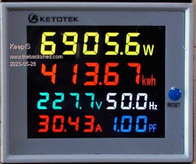 BELOW: Everything looks good to me: Toriod obviously silent. Blue: AC ... Yellow DC input current. 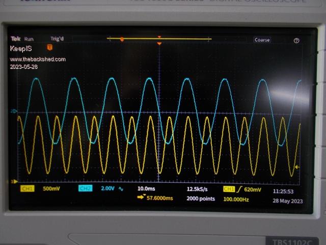 The heatsink on the back of the cabinet: It's the same temperature as the FET heat transfer mounting blocks, so I'm 100% happy with the method I used to couple the FETS, temperature went from 28 to 31 deg after 10 minutes at 7kW. There is ZERO fan cooling. Toriod went from 31 to 35 deg after 8 minutes at 7kW, stayed there as the fans came on and off for a just a few seconds at a time, turned on 3 times. I must change the Fuse block at the input to the inverter - dam thing gets hot - as in burn your fingers, will try a DC/AC breaker the others are using. I need to redo one connection to a chokes and one on the input, they get quite warm, the rest are fine. The Contactor on the inverter: The terminals are the same temperature as the coil and housing, a result of a small holding current in the coil, warm to touch is all. All DC and Toriod connections on wiseguys power board are only slightly warm to touch, I've been checking them under every heavy load, they appear to be a real quality high current screw connectors, board warm slightly after 10 minutes. The rest of the external Battery supply chain, interconnects, fuses and breakers are at room temp. I think that's a good effort for its first run at a high constant power level, even if it was only for 10 minutes - small steps! . Edited 2023-05-28 15:18 by KeepIS NANO:Inverter V 8.2ks - Linux AvrDude GUI script V4.1 |
||||
| KeepIS Guru Joined: 13/10/2014 Location: AustraliaPosts: 2162 |
Found the problems with the connections mentioned above, 1 bad termination and the wrong washer on a another, must have grabbed the wrong one when assembling it the other day. I think I fixed the big Fuse holder, which BTW is not there to protect the Inverter board or FETS, the Caps themselves will make sure there is nothing left to protect, it's only to stop the heavy DC cables from causing havoc if they somehow shorted, the fuse works, I tested it, well, I spot welded a steel bar across two terminals when I tried to test it, it blew, so I guess it's tested  I'll repeat high load testing tomorrow and recheck all the connections once more. A poor pix of the new Chokes installed, 4 turns on each, they are on standoffs, so they look a bit taller then they really are. A blue toriod ring on each end of 4 black toriods rings. As mentioned before I used what I had. 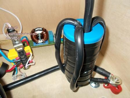 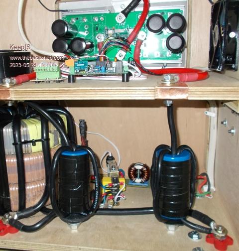 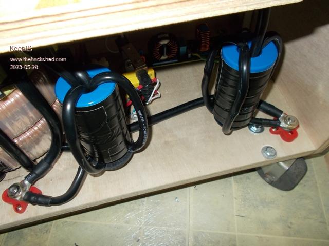 . Edited 2023-05-28 18:51 by KeepIS NANO:Inverter V 8.2ks - Linux AvrDude GUI script V4.1 |
||||
| analog8484 Senior Member Joined: 11/11/2021 Location: United StatesPosts: 201 |
Interesting that the combined chokes (2x23uH) is back close to the often recommended 47uH value. I wonder if there is a calculation somewhere showing how the 47uH value was determined. |
||||
| analog8484 Senior Member Joined: 11/11/2021 Location: United StatesPosts: 201 |
I guess there is no other way to test. Did the BMS shut off? |
||||
| KeepIS Guru Joined: 13/10/2014 Location: AustraliaPosts: 2162 |
That's always been a ball park, but it's high for this inverter, around 37uH is the best value for those loads that cause this inverter to complain. The DSO backs that up. When I have more time I plan to take one toriod ring off and check the value, then swap the colored rings around in combinations until I get the value I need for the sweet spot. Fuse Test: Testing the fuse like that is unlikely to trip the BMS units, the combined Battery bank can supply almost 900A at 48v for a brief time, around 400A continually, and 500A for a few minutes before tripping. There are three LiFePO4 battery banks, each fused with a similar 100A fuse, so a flash blow of a separate Fuse in the inverter is not going to bother those either. A BMS will likely open before a Battery fuse blows in any case, the Fuses are there for worst case scenarios. Each battery bank has it's own Isolating switch, Solar Charger and Solar array. Three of everything and an inverter than can have the driver boards swapped in 10 minutes, redundancy! The system can run "essential power" on only one 8kW bank if needed. Finally, any Inverter fault or external fault that cuts DC input to the Control circuits in the inverter, before or after the Inverters input Contactor, will cause the 900V-500A rated Contactor to instantly open. . Edited 2023-05-29 10:10 by KeepIS NANO:Inverter V 8.2ks - Linux AvrDude GUI script V4.1 |
||||
| KeepIS Guru Joined: 13/10/2014 Location: AustraliaPosts: 2162 |
Chasing the elusive Choke inductance There is nothing like high power sustained running to show up any weakness in your inverter. There are a few reasons for doing this at 7kW to 8kW, which I reached today, but 8kW was for only 1 minute as the large Inverter input Fuse holders big cable connecting blocks were boiling and evaporating fluid on the moisture test. Wiseguy did not design the power board to run this hard for any length of time. I believe his power board was designed with the idea of easily using two or more power stages in parallel to run unstressed at high continuous power. So, 7kW to 8kW gives me an idea of the limits of the boards power and Toriod connections, these can be increased / complemented by using the Heat sink for some power connections, in my case the FETS are connected directly to the very thick Heat transfer Bars, so that's easy to do. It also tests the dual sided thick copper power tracks capacity on the PCB for up to 10 minutes, and at a higher power then I'm sure they were really designed for, Mike may elaborate on that, and it also allows me to push a little harder to test the FET heatsink coupling design that I used. The elusive Choke Inductance: This has been the best test I have had for absolutely selecting the Inductance value for my Choke, and the effect it has on nasty loads. I am fortunate to have FIVE Toriod ringing / prodding loads, and was able to compare the initial changes to the Choke value and the difference changes as small as 5uH in a Choke can make to the inverter. My Wife informs me that the Hair curler is a Hair straightener, horrid devices for Toriod noise and I have access to an old and new unit. I have Two Heatguns, one has variable Heat on High and LOW which BTW still appears to have a Diode in series on low, the other is just HI-Low heat with a diode in series on Low, finally the Reverse cycle AirCon on Heat at Full output. RECAP: LOAD: Hair straightener. Choke inductance 73uH: Sounds like a bucket full of bolts rattling, very loud and causing the UPS to beep like crazy and the lights to flash like a disco dance floor. Choke inductance 37uH: The noise now a slight background buzz and nothing else, no Disco or UPS beeps. Choke inductance 46uH: The noise still a slight background buzz and nothing else, no Disco or UPS beeps. __________________________________ LOAD: Reverse Cycle Inverter AirCon on High heat drawing 2.2kW. Choke inductance 73uH: Extremely LOUD BUZZ, the UPS beeping like crazy and the lights flashing madly. Choke inductance 37uH: Total Silence. Choke inductance 46uH: Total Silence. __________________________________ LOAD: Heatguns on Low. Choke inductance 73uH: LOUD HUM, I would NEVER leave it running. Choke inductance 37uH: Subdued Hum, you could leave it on and not worry. Choke inductance 46uH: Subdued Hum, you could leave it on and not worry. __________________________________ Rewound Chokes: I removed one Blue toriod and got the inductance down to 20uH from 23uH. Total inductance is now 40uH down from 46uH. 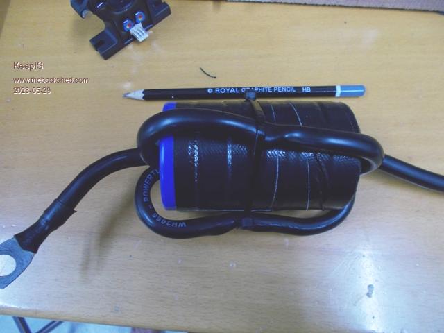 Below: Saturation curve for One 20uH Choke, there are two Chokes in the Primary. V-scale: 250A per division: 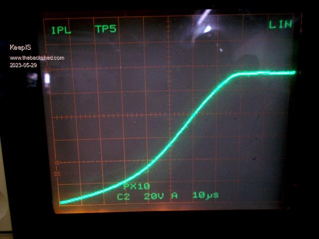 __________________________________ Today: Before changing from 46uH to 40uH, I re-tested the Inverter with the Hair straighteners plugged in very close to the Inverter. All other loads are always near the inverter. Hair straightener. 46uH Choke The UPS started to beep, but noise was still not "to" bad. Choke 40uH The UPS is silent - buzz is just in the background. Everything else was silent at 40uH. Final result: 40uH is close to the sweet spot. The Inverter is now running with two 20uH chokes, one 20uH choke in each side of the Toriod Primary. I have some DSO Screen shots of the Hair straightener waveforms to follow, and the startup waveforms and current using the 40uH choke, which show that 40uH is better then 46uH at extremely high demanding 3Hp Induction motor loads. I'll do that tomorrow. . Edited 2023-05-30 08:46 by KeepIS NANO:Inverter V 8.2ks - Linux AvrDude GUI script V4.1 |
||||
| KeepIS Guru Joined: 13/10/2014 Location: AustraliaPosts: 2162 |
Bad Inverter Loads: Briefly and simplistically generalized by myself: Going back 7 years in various forum postings, the decision when choosing a Choke was initially around the lowest Idle current, the rational was sound, it was realized that normal inverter loads were around 300 to 1kW 99% of the time and for a number of reasons, most of us went for the lowest idle current. We still make that choice, but in my case I have proven that it's not really a compromise to get a Choke that virtually stops 99% of the noise, even with bad loads, even loads that in the past would destroy some inverter, obviously "DUH" this can "not" be put down to simply changing a Choke. The typical Waveform: 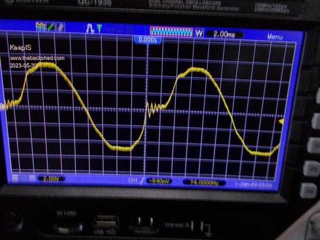 ABOVE: This is what you see with Heatguns that switch a Diode in series with the Heating element on LOW. The same thing happens with the Hair Straighteners, and even the AirCon. Choke value was around 58uH, very high saturation chokes in all cases. This was with the China inverter in the Cabinet, I never bothered with capturing an image of the New inverter board running this load, but it was quieter, still made you want to turn it of "quickly" though. These Loads vary in how deep they cause a step into the waveform, other waveform distortions and how much ringing they cause. Almost like hitting something with a hammer, in this case the Toriod, and making it ring. I've found that one change I can make in the Inverter that has a very noticeable change to the amount of ringing, Toriod noise, and helps reduce the step in, or at least reduce the sharp edge nature of it, is the Choke inductance. Below 37uH to 40uH Choke: 30A peak DC input and the step around 6A, the AC load is around 400 watts The ringing has completely gone from what I was seeing the other day, and the step in is less. There is only a small value of current at the step. This inverter is now very quite running this load. Before it was scary loud, flashing Workshop lights and UPS beeping like crazy. 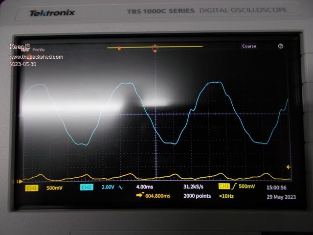 Idle Current: Chokes: 37uH to 75uH give virtually the same Idle current in this Inverter. Bare transformer tested with a Variac, 14 turn primary @ 27.3VAC for 230VAC out @ 15 Watts. Tested again with 40uH Choke: The Inverter Idle current is 22 watts running "Wiseguys" Controller board and Inverter power stage, along with LEDS and a small relay. It raises to 27 watts with two the bigger DC to DC power packs running and the big Contactor engaged. This is virtually the same as the China Inverter board. . Edited 2023-05-30 11:47 by KeepIS NANO:Inverter V 8.2ks - Linux AvrDude GUI script V4.1 |
||||
| KeepIS Guru Joined: 13/10/2014 Location: AustraliaPosts: 2162 |
DE - Induction motor startup with 2 x 21uH Chokes: The 100Hz DC current no longer varying between half cycle pulses for each complete 50Hz cycle. There is no longer any ringing in random cycles of the 230vAC waveform. 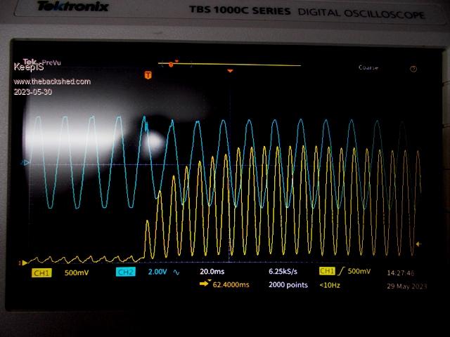 Closer look at startup: Reaching 312A peak input at the 4th cycle, and on it's way to 380A which will hold for 2.5 seconds before falling off.  . NANO:Inverter V 8.2ks - Linux AvrDude GUI script V4.1 |
||||
| KeepIS Guru Joined: 13/10/2014 Location: AustraliaPosts: 2162 |
Compressor startup: 2 x 20uH chokes. The DC input current peaks reach 550A, around 15A less then with the 45uH choke, but can't really rely on that as so many environmental and physical conditions can effect that. Once Again when I examine the full images, there is no longer any ringing in random AC cycles. The variation in DC Cycles is almost nonexistent. The startup is much cleaner with almost no ringing as the load is dropped onto the inverter. 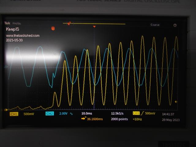 When I get a chance I'll post a capture of the 46uH choke introducing random ringing in to the AC, that has gone in all of the 40uH captures. . Edited 2023-05-30 13:49 by KeepIS NANO:Inverter V 8.2ks - Linux AvrDude GUI script V4.1 |
||||
| KeepIS Guru Joined: 13/10/2014 Location: AustraliaPosts: 2162 |
The DE Startup, I posted before the last one above at 12:02pm 30 May 2023. I've posted it here again, 40uH choke start compared to the 46uH choke A noticeable difference in ringing. It continues throughout the AC startup at random times. Choke 40uH. 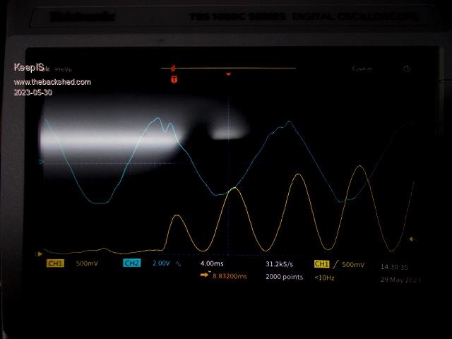 Choke 46uH 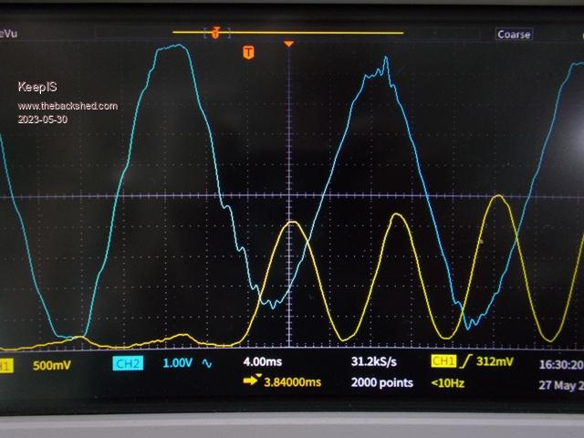 . NANO:Inverter V 8.2ks - Linux AvrDude GUI script V4.1 |
||||
| Murphy's friend Guru Joined: 04/10/2019 Location: AustraliaPosts: 675 |
Thanks for all your testing Mike, its very educational. Just to be sure we compare apples to apples can you mention your inductance tester and at which frequency it tests the inductance of your chokes? I have a reasonably good tester, it only does inductance and capacitance. But, as I'm still on the road, I don't have the specs handy to see what is the test frequency. |
||||
| KeepIS Guru Joined: 13/10/2014 Location: AustraliaPosts: 2162 |
Hi, the Inductance is calculated from the resonant frequency of the choke with a known value of parallel capacitance. In my case 4.08uF. I have a Vector analyzer and other RF equipment but I find this method gives me 100% consistent results for these types of chokes. I think the way to select a Choke is to first find the value that gives you the lowest Idle current before it starts to drop off slowly, then test with something like a heating element with a Diode in series, find the Choke value that gives you the least Toriod noise with the least ringing. Lastly, the choke should not saturate until at least 300A for a small inverter that's not starting big induction motors or thinks like Drop Saws. For heavy loads IMHO, the Choke should still have some inductance past 600A. Then, if idle current is higher than you would like with the best Choke value for noise and load handling, you obviously have to decide what you are willing to trade off. Sometimes you get a lucky combination where there is no real trade off to be made. In any case, I would be uneasy going much below 25uH in big choke with very few turns, but that's more a personal feeling I have around some R-Loss and the Q of the Choke. EDIT: I was just looking back and found a test that Poida did: Perhaps the minimum saturation point should be around 400A and not 300A, I believe Poida was measuring the Primary current. Which stands to reason as the FET Switching currents can be higher then DC input current depending on the Duty cycle. . Edited 2023-05-30 19:35 by KeepIS NANO:Inverter V 8.2ks - Linux AvrDude GUI script V4.1 |
||||
| KeepIS Guru Joined: 13/10/2014 Location: AustraliaPosts: 2162 |
I know this is likely boring, but, I did get another pix of the Inverters AC OP meter. I didn't catch the 8kW load on the Meter as I had to turn the inverter off due to a Large Fuse holder going into meltdown, not the fuse but the Metal Block cable connections. I did however get the 7kW+ reading, it was varying between 7.1kW and 7.3kW at the time. 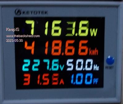 . NANO:Inverter V 8.2ks - Linux AvrDude GUI script V4.1 |
||||
| tinyt Guru Joined: 12/11/2017 Location: United StatesPosts: 559 |
Can the inductance be calculated/estimated using the results from a choke saturation tester? |
||||
| KeepIS Guru Joined: 13/10/2014 Location: AustraliaPosts: 2162 |
Yes, Poida discussed the correct way and the math to do this using a saturation tester and DSO. It also allows you to calculate the Inductance at various points as you climb the slope to full saturation. It's only as accurate as the particular Current Sensor. I find the unidirectional DC Hall current sensors I use have response times in microseconds, whereas most of the AC sensors I looked at were quoted in tens of milliseconds. Forgot to add, I tested my Sensor against a Big resistive shunt, it was almost as fast as the Shunt, and matched it way past 600A, the only thing between the DSO and the Shunt was a piece of shielded coax, so pretty impressed with the Hall Sensor. The advantage of good Hall Sensor is Isolation from High current spikes and noise in the Choke and discharge power driving it, obviously something a shunt is physically connected to. . Edited 2023-05-31 08:44 by KeepIS NANO:Inverter V 8.2ks - Linux AvrDude GUI script V4.1 |
||||
| tinyt Guru Joined: 12/11/2017 Location: United StatesPosts: 559 |
Thanks to you and Poida. I bought this 200A inductor which does not publish its inductance. So, I made a tester from your schematic, total capacitance is 20000 uF. 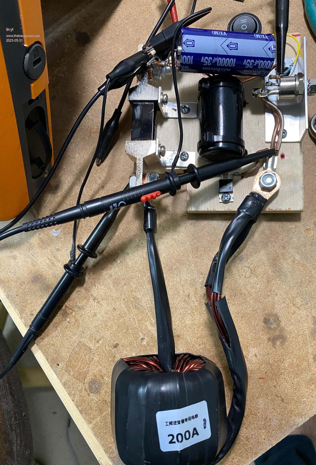 Took me some time to make the scr trigger work. I used a 200A 75mV shunt, and a DSO. I enabled bandwidth limiting for both channels to filter out some of the 'noise'. 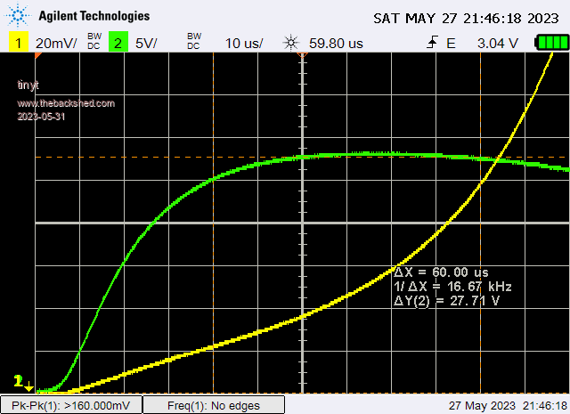 Luckily the DSO I borrowed can save readings in excel format (csv). But I think bandwidth limiting is not applied to the numbers. I did some calculations to selected ranges. Red colored numbers are what I think the approach to saturation. 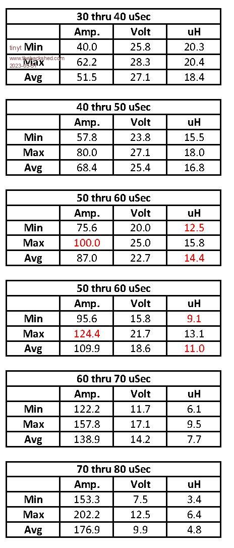 Looks like its inductance is a little low for the inverter I am making. Thanks for sharing your work. Edited 2023-05-31 12:38 by tinyt |
||||
| KeepIS Guru Joined: 13/10/2014 Location: AustraliaPosts: 2162 |
Great work, I had a similar choke from China, it was wound on 3 Black toriod rings, same Toriods as I'm using for the Chokes I make. I think the current rating they advertise is the current the choke will handle without melting The Inductance was supposed to be 47uH (where have I heard that value before) and made for their big inverter boards. Turned out to be around 39uH, saturation was still fair at around 220A, which is never going to cut it for a decent inverter. As you measured, there is not much Inductance left for big loads, OK for reducing idle currents, but nothing left when the going gets tough. BTW: Found a permanent fix for the melting Fuse holder - I removed it  I'm going to do something I've been wanting to do for a while. Fit a 500A [700A] peak Hall Sensor on the DC input, and as the voltage output is so stable, accurate and noise free, it can be easily set to an exact Trip current, I'll use that to halt the Inverter drive and throw the Big Contractor solenoid open in the event of a catastrophic current surge. . Edited 2023-05-31 14:29 by KeepIS NANO:Inverter V 8.2ks - Linux AvrDude GUI script V4.1 |
||||
| KeepIS Guru Joined: 13/10/2014 Location: AustraliaPosts: 2162 |
AC waveform at 2.3kW. A big VFD Lathe under load and Dust-ext Induction motor running, along with the rest of house loads. Something that causes a flat top appearance on the AC [Mains and Inverter AC] was not running at the time, I must hunt that down, I still think our huge Inverter Fridge Freezer is almost always sitting across the AC supply and just idling along and causing this. 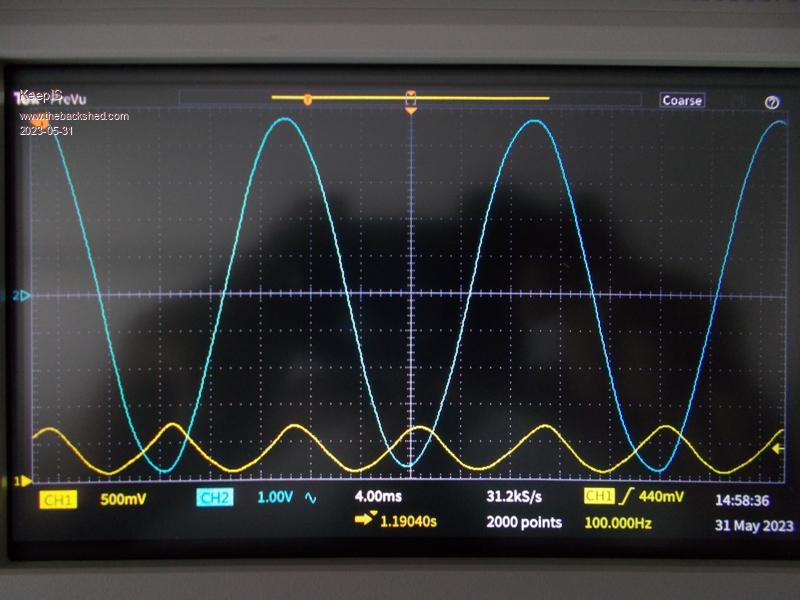 . Edited 2023-05-31 15:25 by KeepIS NANO:Inverter V 8.2ks - Linux AvrDude GUI script V4.1 |
||||
| The Back Shed's forum code is written, and hosted, in Australia. | © JAQ Software 2026 |
