
|
|
Forum Index : Electronics : Hopefully? Another 48vdc-240vac Toriod Inverter build.
| Author | Message | ||||
| KeepIS Guru Joined: 13/10/2014 Location: AustraliaPosts: 2193 |
The P-detector follows the peaks of the rectified waveform, it's normally preceded by a Precision Full-wave rectifier, the P-rectifier @ 50 Hz would produce the 100Hz 1/2 wave waves that you normally see from any full wave rectifier, but without typical Diode non-linearity. Which is why I thought the Peak-detector would be ideal for this task as the unidirectional Hall sensor output is not unlike a rectified AC signal. The waveform on the DC input cable to these inverters will always have a 100hz waveform when the inverter is running, that is produced by the FETS drawing current to make a 50Hz "AC" waveform from a DC input. The waveform on the DC input is not an AC waveform, it's not alternating current or voltage, it's more like 100hz DC pulses shaped like a sinewave, there is no zero crossing. The zero current point is at the base of the waveform. As far as the peak detector is concerned, this waveform looks the same as 100Hz full wave rectified 50Hz AC without any filtering. Not that the frequency matters. So trying to calibrate it with a straight DC signal is not going to work. Trying to use an sinewave generator is not going to work, it's not the same thing. You really need the waveform shape from the Hall Sensor that is on the DC input of your Inverter, whatever wave shape comes out of the sensor from the Current flowing into your Inverter should stay relatively the same at all power levels, unless you have an unknown problem in the inverter. However there is a way to calibrate the meter and get accurate information from the Hall Sensor. I mentioned a low cost (relative I guess) handheld Digital Oscilloscope / DSO a few pages back. I managed to figure how to get it to grab the waveform on trigger, I got the end of the startup waveform before it wound down to running current. It was spot on in the values returned and the waveform is exactly the same as my big TEC DSO. That was on my second go having never played with the Mini digital CRO before, it's not a true DSO with scroll-able memory, but you can grab the waveform and view it, and it will tell you the correct values. I need to test it bit more tomorrow, to see if it can reliably trigger and capture the part of the startup waveforms we need, but it looks good so far. BTW it displays the Inverter AC and DC current waveforms perfectly when running as a straight Digital CRO. It might be something to consider, I think around $75 for this one, likely lower cost units are around, just check the spec as some are nasty, this one was on spec at 500kHz bandwidth and only slightly down at 1Mhz. 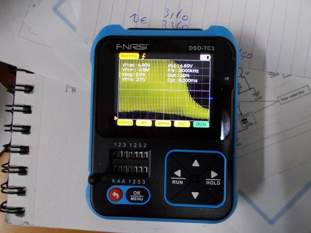 Link to CRO You want Color Set 2, it has the CRO Probe and Adapter $78. . . Edited 2023-06-06 20:17 by KeepIS NANO:Inverter V 8.2ks - Linux AvrDude GUI script V4.1 |
||||
| tinyt Guru Joined: 12/11/2017 Location: United StatesPosts: 560 |
I thought I can use the existing shunt jumpers and opamp (IFB) on the chinese inverter board I am using. 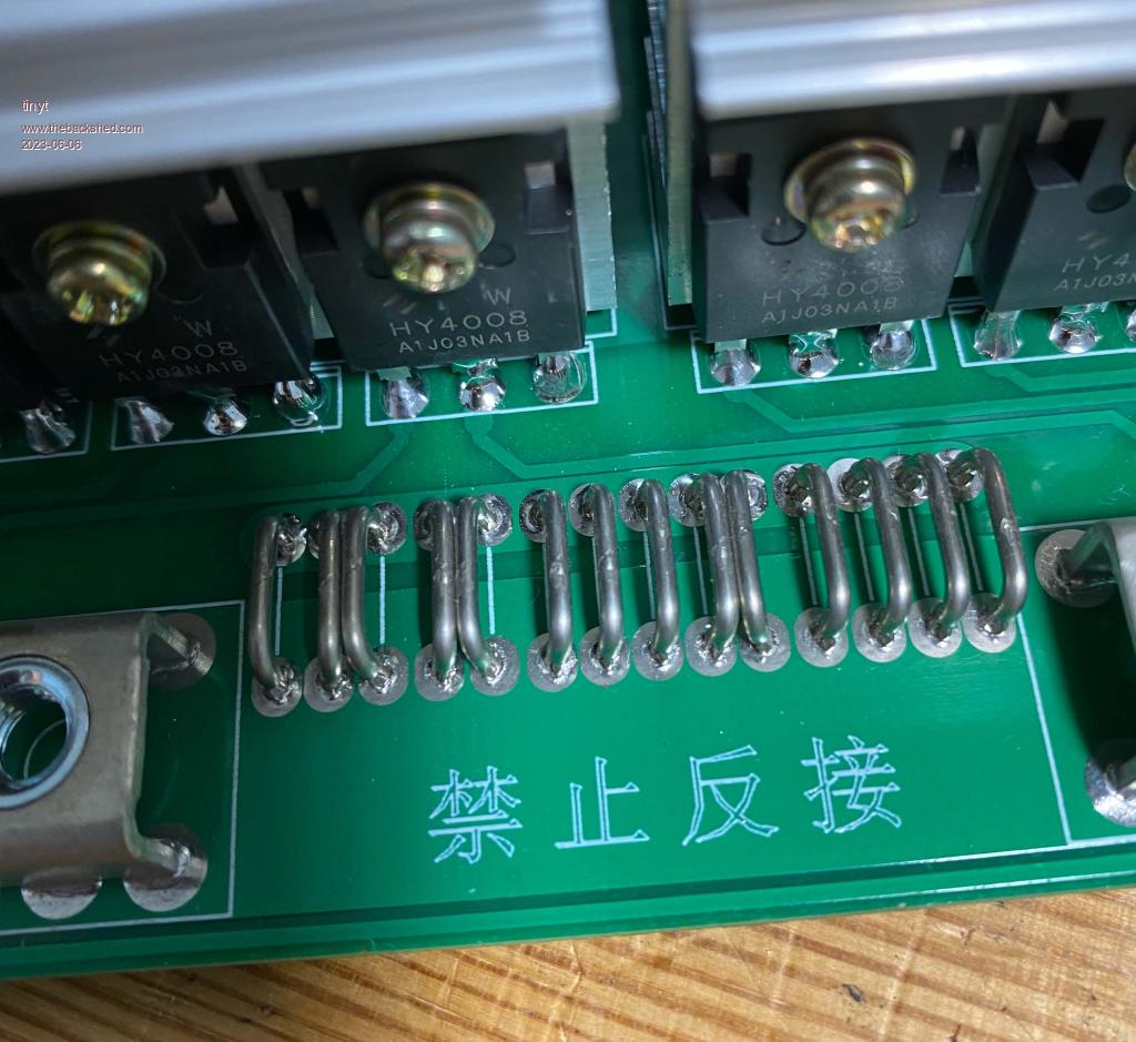 Also, doesn't the bulk electrolytics on the power board filter out the sinewave current? |
||||
| nickskethisniks Guru Joined: 17/10/2017 Location: BelgiumPosts: 481 |
No, the capacitors only filter the voltage and keep ripple voltage low. To remove the current ripple on the DC you would want a really big inductor... |
||||
| tinyt Guru Joined: 12/11/2017 Location: United StatesPosts: 560 |
Ah, OK thanks for the info. |
||||
| analog8484 Senior Member Joined: 11/11/2021 Location: United StatesPosts: 204 |
It's a bit surprising that connection R-loss can have enough dynamic changes to have significant effects. I guess it's another reason to have as few connections as possible. Edited 2023-06-07 04:18 by analog8484 |
||||
| KeepIS Guru Joined: 13/10/2014 Location: AustraliaPosts: 2193 |
Or have more parallel connections to each high current interface point. Like some of the bigger Inverter builds that have been described in the past, most usually have 3 or 4 parallel connections to the FETS and Heatsinks [if not isolated] and 4 or more to the DC inputs on the boards. 585 Ampere pulses at 100Hz are significant and connections can generates significant noise throughout an inverter, these currents are normally not encountered in the average Home built house hold Inverter. The reason why I spent a lot of time looking at what was really going on in the Inverter at these power levels was to highlight the important areas to give even more focus to then we usually do, and to give the Inverter the best chance of surviving. If you have some idea of what your dealing with you can make an informed decision about how to build it. . NANO:Inverter V 8.2ks - Linux AvrDude GUI script V4.1 |
||||
| KeepIS Guru Joined: 13/10/2014 Location: AustraliaPosts: 2193 |
Those shunts are on the FETS and the currents you see there are more complex then the DC inputs, they are not a straight correlation to DC input and the Noise there would be horrendous. To add to what has been said about the filter caps. The Caps smooth out the voltage variations as current is drawn, the Load Current causes this voltage variation and the caps try to smooth that out. But that's not what the Sensor is showing, the Sensor is showing the Current flowing through the Cable, not the voltage variation of DC supply on the cable, although they will look similar. The more capacitance you place across the DC input, the more current the caps can help supply to the FETS, helping to reduce cable loss, noise and voltage variations right at the Inverter / FET connections terminals. . Edited 2023-06-07 09:30 by KeepIS NANO:Inverter V 8.2ks - Linux AvrDude GUI script V4.1 |
||||
| KeepIS Guru Joined: 13/10/2014 Location: AustraliaPosts: 2193 |
For anyone considering one of the small DSO units I linked to, I carried out a series of tests with various loads, it has no problem capturing the waveform startup and showing the correct values and the captured screen has very good detail. This has the Display of the Dust Extractor. BTW This DE is mounted in a 3m high external enclosure. The value display is toggled off to show the screen display clearly. 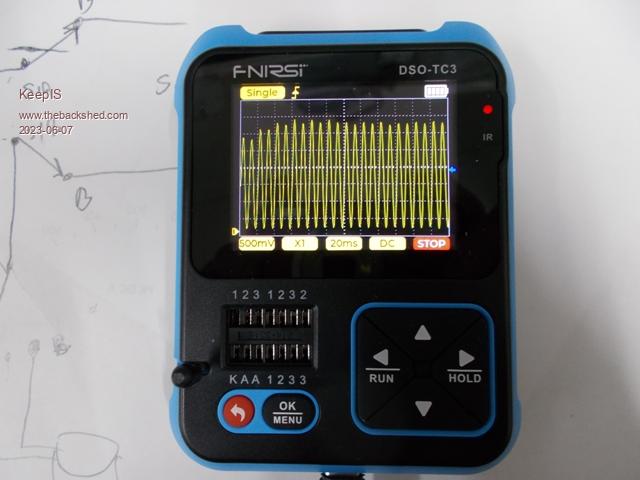 Below: The Meter showing the Compressor startup of 560A - Pretty darn close. Note the startup current can vary from around 560A to 587A with temperature, load pressure and other factors. 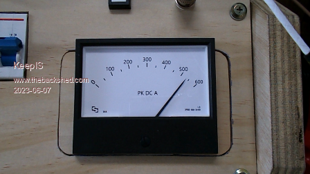 . Edited 2023-06-07 11:30 by KeepIS NANO:Inverter V 8.2ks - Linux AvrDude GUI script V4.1 |
||||
| Pete Locke Senior Member Joined: 26/06/2013 Location: New ZealandPosts: 184 |
I bought one, and very pleased with it. Handy tool box addition indeed. Only used a couple of times in anger servicing, but a lot quicker than setting up the Rigol. Cheers Pete'. |
||||
| KeepIS Guru Joined: 13/10/2014 Location: AustraliaPosts: 2193 |
Thanks Pete for the info, up until now I've been using mine mainly for the auto identification of components, just stick a FET or Transistor in holder any which way and have it tell me what it basically is, and give me the correct Pin out connections. Saved me so much time going through boxes of old components. . NANO:Inverter V 8.2ks - Linux AvrDude GUI script V4.1 |
||||
| Murphy's friend Guru Joined: 04/10/2019 Location: AustraliaPosts: 678 |
That sounds like a good reason for me to order one too. I have many new & recycled semiconductors and that DSO would be handy to sort what is what. Being able to catch & hold peak wave forms makes it even more useful. |
||||
| KeepIS Guru Joined: 13/10/2014 Location: AustraliaPosts: 2193 |
Hi Klaus, Most of these things turn out to be semi-useful but this surprised me, and running on a battery with good life is also a plus. The only thing to be careful with is this: The input range on lower sensitivity, like 20mv, 40mv, 100mv per division can catch you out when using DC coupling and moving the vertical display position cursor to the bottom of the screen, which is what I do when reading from a sensor that has only positive displacement output from zero. The input appears to be designed for typical sinewave input shown as +- around center, cursor at center of the screen. It appears that the input amps overload and peak clip if you try to show a signal that is a full screen positive going waveform starting from the bottom of the screen. On higher settings like 500mv per division, which should be used for the Sensor I have anyway, the head room is fine if the Cursor is moved to the Base line. No clipping on full screen and the correct voltages are displayed. Hope that makes sense. . NANO:Inverter V 8.2ks - Linux AvrDude GUI script V4.1 |
||||
| KeepIS Guru Joined: 13/10/2014 Location: AustraliaPosts: 2193 |
The Beast tarted up  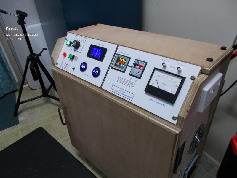 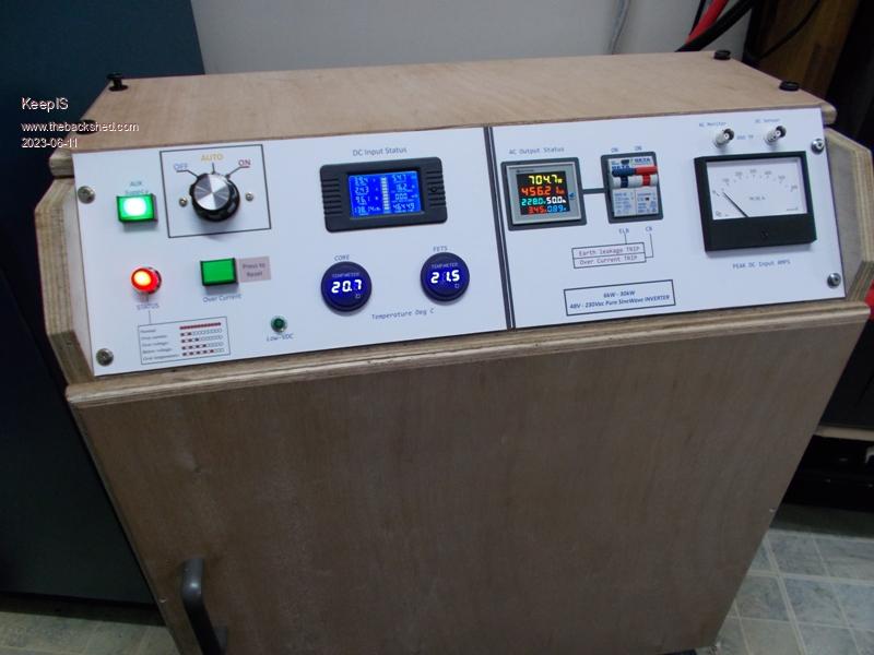 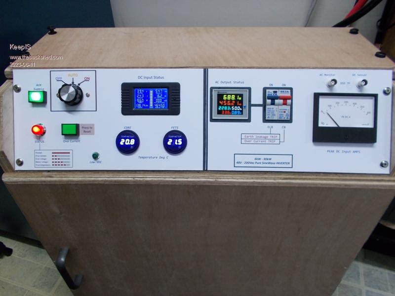 . NANO:Inverter V 8.2ks - Linux AvrDude GUI script V4.1 |
||||
| Murphy's friend Guru Joined: 04/10/2019 Location: AustraliaPosts: 678 |
Very pretty Mike, what is the display panel made of? Did you varnish the plywood case or is that not on the list? |
||||
| KeepIS Guru Joined: 13/10/2014 Location: AustraliaPosts: 2193 |
Thanks Klaus, The case is about to have its varnish or oil, hopefully I'll finish that today. The Display panel finish is Photo paper, I scan the very wide base front panel in two scans, two by A4 sheets wide. Spend a day in Photo shop and design the front panel, Obviously everything must scale and print exactly, which it does. The Printout on Photo paper is then given 3 coats of acrylic Clear. I've been doing this for over 20 years on my projects, still have 3 pieces of gear done like that and they are as good as the day I made them. Turns out to be a pretty tough finish. Notice the LED status codes on the bottom LH side for the eg8010 codes  BTW: The front panel is wired up on the workbench, I made it a plug in Unit. Four screws, unplug the front panel, and take over to the workbench for any changes. 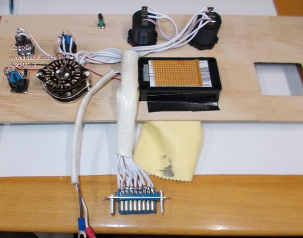 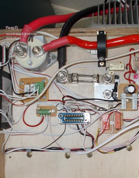 . Edited 2023-06-12 16:09 by KeepIS NANO:Inverter V 8.2ks - Linux AvrDude GUI script V4.1 |
||||
| KeepIS Guru Joined: 13/10/2014 Location: AustraliaPosts: 2193 |
Coat of Danish Oil. 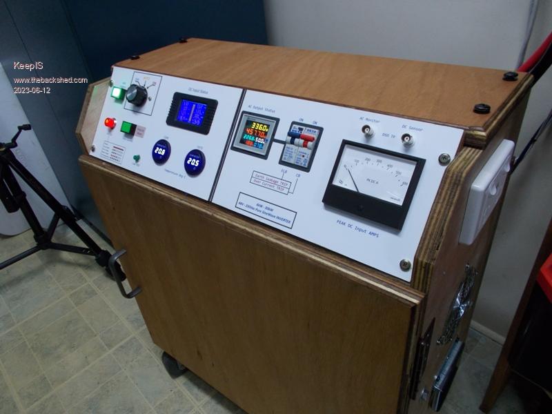 . NANO:Inverter V 8.2ks - Linux AvrDude GUI script V4.1 |
||||
Revlac Guru Joined: 31/12/2016 Location: AustraliaPosts: 1282 |
Now that looks like a proper job Mike,  always nice to see other's ideas when building these things, was the printing done with colour Laser or Inkjet? I mostly have trouble with Ink fading but its mostly out doors. always nice to see other's ideas when building these things, was the printing done with colour Laser or Inkjet? I mostly have trouble with Ink fading but its mostly out doors.Cheers Aaron Off The Grid |
||||
| tinyt Guru Joined: 12/11/2017 Location: United StatesPosts: 560 |
I use this self-adhesive laminating sheet or this to protect printed labels, not sure if it will prevent fading. |
||||
| KeepIS Guru Joined: 13/10/2014 Location: AustraliaPosts: 2193 |
Thanks Aaron, Just a colour Inkjet, the 20 year old units have not faded, but used mostly indoors. The good quality clear coats seem to be really tough, I follow up the initial 3 coats with another few coats once the Photo sheets are glued to the base front panel. Thing is they cost me virtually nothing to make, not much ink and the glue I use allow the sheets to be peeled off, So easy to print another and replace it. Thanks, that is slightly different to what I have tried before, I had problems with glare reflecting and some slight ripple with other laminating products on large thick photo paper panels. I may get some and test them out, they look like they may work, would save spraying wait time. The clarity and quality of the Front panel in the Pictures I posted does not do it justice, it's a really beautiful finish. Still couldn't get a pix of how crisp and sharp as really is. 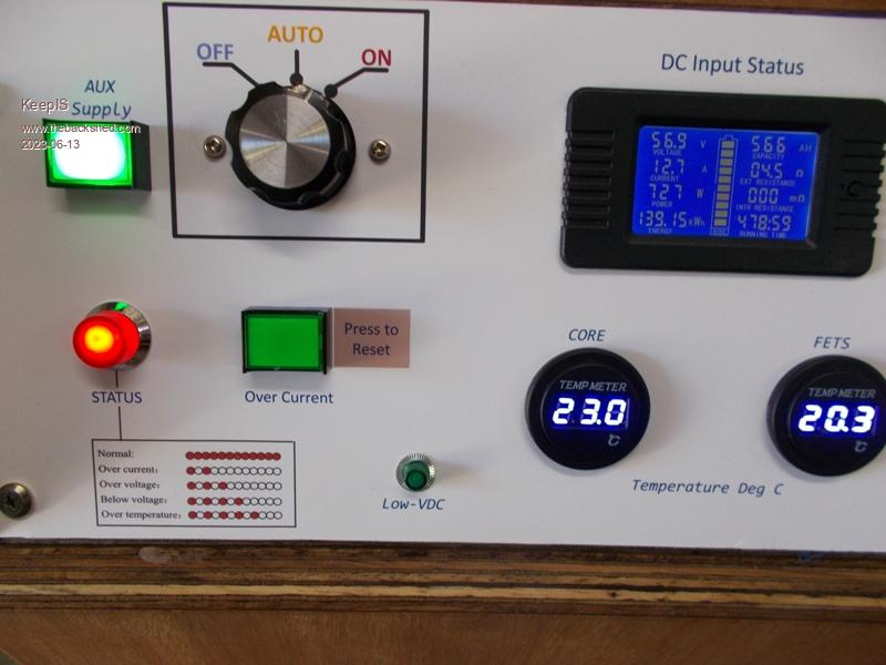 . Edited 2023-06-13 09:30 by KeepIS NANO:Inverter V 8.2ks - Linux AvrDude GUI script V4.1 |
||||
| Revlac Guru Joined: 31/12/2016 Location: AustraliaPosts: 1282 |
Definitely a nice clean printed finish, reminds me of my old Cannon IP4200, used to do a great job till it started mixing the ink inside the tanks instead of at the print head. I have some of those laminated pouches so might have ago at that too. Cheers Aaron Off The Grid |
||||
| The Back Shed's forum code is written, and hosted, in Australia. | © JAQ Software 2026 |
