
|
|
Forum Index : Microcontroller and PC projects : HC-12 old vs new module....
| Author | Message | ||||
palcal Guru Joined: 12/10/2011 Location: AustraliaPosts: 2039 |
Well I learnt something, PogoPins never heard of them before but I will have some soon. No idea what I'll do with them though. Paul. "It is better to be ignorant and ask a stupid question than to be plain Stupid and not ask at all" |
||||
Chopperp Guru Joined: 03/01/2018 Location: AustraliaPosts: 1126 |
Likewise Paul. Had to do look them up as well. ChopperP |
||||
Grogster Admin Group Joined: 31/12/2012 Location: New ZealandPosts: 10000 |
Pogo pins are awesome things for programming jigs.  I have located six of the remaining eight of the HC-12's from November's purchase of fifteen units. I only have two left to find now. All units were checked using the scanner and frequency counter. Any that register as being off-frequency are being marked as such, and put to one side. It looks like I might be doing a bit of re-building. Curses!    Oh well. Faeces occurs....... Smoke makes things work. When the smoke gets out, it stops! |
||||
| palcal Guru Joined: 12/10/2011 Location: AustraliaPosts: 2039 |
I can't figure how you would mount them on the PCB, a pic. of the finished board would help. What were they originally used for. Paul. "It is better to be ignorant and ask a stupid question than to be plain Stupid and not ask at all" |
||||
| Grogster Admin Group Joined: 31/12/2012 Location: New ZealandPosts: 10000 |
Assuming you mean the Pogo pins, I use TWO of the same board, stacked with short spacers between them, and a small offcut of PCB taped to the bottom of the bottom PCB covering the pogo-pin holes. This prevents the pins dropping right through both boards, and also ensures that all pins are at the same height. Then you push the pogo pin through BOTH boards from the top(which are now stacked), and solder the pogo pin to the top of the via on the top board. Both stacked boards keep the alignment almost perfect at 90' to the horizontal of the PCB. That done, remove the top PCB, and solder the bottom side of the vias on the top board you just removed. I find that it is best to then replace the top board in the bottom one, as that protects the pogo pins from damage. Like this: 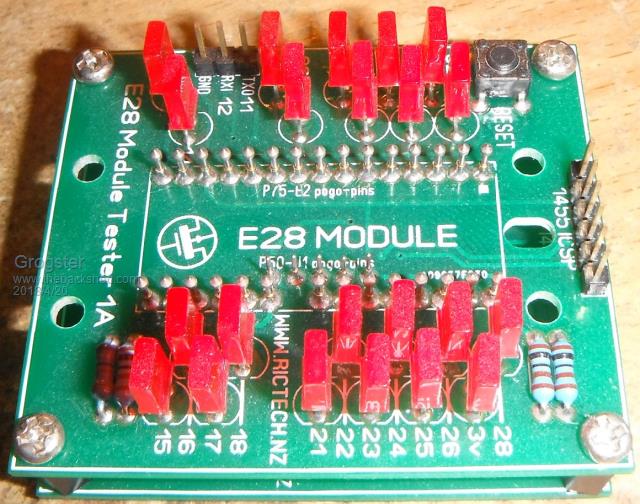 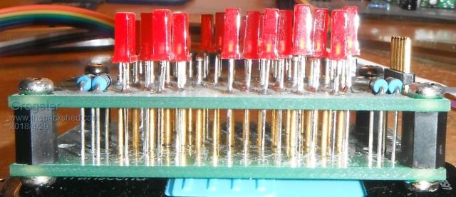 The PCB does benefit from having close-fitting vias for the pogo pins, as that also helps keep them square to the PCB. I usually make the hole in the via 0.1mm wider then the pogo-pin, that way, they are a snug fit. Smoke makes things work. When the smoke gets out, it stops! |
||||
| palcal Guru Joined: 12/10/2011 Location: AustraliaPosts: 2039 |
What a great idea. Paul. "It is better to be ignorant and ask a stupid question than to be plain Stupid and not ask at all" |
||||
| WhiteWizzard Guru Joined: 05/04/2013 Location: United KingdomPosts: 2991 |
By the way - DO NOT buy cheap Pogo Pins as they will fail quicker than they should. Then you're left with a different problem to resolve . . . . Look at the cost of pins in somewhere like RS - then compare them to the likes of eBay. In 2014 I used a 7 way pogo-pin 'package' in a design - they cost (back then) �3.18 each - but they still work 100% reliably today. Note to Grogs: My E28 tester has had three pins swapped out already in its 'brief' life  |
||||
| Grogster Admin Group Joined: 31/12/2012 Location: New ZealandPosts: 10000 |
Really?! That's interesting. A metal pin is a metal pin. I wonder what went wrong with them? How many E28's have you tested in your one before you had to replace pins? I have done heaps, and that arrangement as posted above is still working fine. Probably tested about 75-100 modules in that rig so far, and still working......  Smoke makes things work. When the smoke gets out, it stops! |
||||
Azure Guru Joined: 09/11/2017 Location: AustraliaPosts: 446 |
@Palcal Pogo pins came from bed of nails test rigs. Back when PCBs used to be expensive to make and most boards were sizeable. To make a test PCB was not a cost viable option a lot of the time. Instead they would make a test jig (there were modules sort of like meccano/lego) that you could use to hold the test pins or (hopefully properly) drilled baseplates, made from various insulating materials. These were then hand wired up to a harness which was then wired to test connectors and/or connected to the testing system. For large production runs these systems were also automated and the test jig could be swapped (hence the connectors) for testing different boards with a smart(er) testing system controlling and checking it all. Ahhhh, that takes me back down memory lane :) |
||||
| Grogster Admin Group Joined: 31/12/2012 Location: New ZealandPosts: 10000 |
I have finished testing all the modules I could locate here from that November batch, and ALL of them have the same frequency error, so it is not just one or two. That's thirteen modules out of fifteen, all work, but all are 37kHz off frequency. I have yet to find the last two - I can't remember where I installed those ones, but I guess it will come back to me given time.... Smoke makes things work. When the smoke gets out, it stops! |
||||
| CaptainBoing Guru Joined: 07/09/2016 Location: United KingdomPosts: 2171 |
That's not nice Prolly keep them (well marked) for one-offs... like a fancy doorbell or something for your neighbours. (on a channel way-up so your stuff doesn't get swamped  ) )what a pain! HC-12a |
||||
| Grogster Admin Group Joined: 31/12/2012 Location: New ZealandPosts: 10000 |
I have had confirmation from the PICAXE forum, that at least one other person is seeing this issue with their modules: I am trying to find someone local here, who is fluent in Chinese, who can help me correctly translate the hc01 webpage, and perhaps even establish contact with them on my behalf. Oh how I wish they had an English version of their site. I would order direct from them to be sure of the genuine article, but navigating the Chinese language is a big brick-wall for me. Smoke makes things work. When the smoke gets out, it stops! |
||||
| Boppa Guru Joined: 08/11/2016 Location: AustraliaPosts: 816 |
Jeez, havent seen a pogo stick for years, we had a couple of different types at a place I used to work at, one for testing pcbs after manufacturing (that basically tests the tracks for continuity/shorts before any components were mounted) and others for testing after being populated, where you could test the pcb without having to wire it up, and had breakout points for testing (frequency, voltages etc) Very handy they were One of the biggest issue with cheap pins was they would not always make reliable connections (remember they only work on pressure for conductivity) and cheap tinned (or even untinned!) pins could make intermittent contact, giving rise to false readings and sending you off on a wild goosechase looking for a non existent fault |
||||
Quazee137 Guru Joined: 07/08/2016 Location: United StatesPosts: 603 |
Odd though is if the problem is with a clock function register in the RF chip not being set. Can it maybe set by taking over the SPI interface and talking to it with a mite. Quazee |
||||
| Grogster Admin Group Joined: 31/12/2012 Location: New ZealandPosts: 10000 |
@ Boppa(and WW) Re. Pogo pins: Now I can see why they might give trouble. I will get some genuine ones from Element-14/Mouser/Digi-Key etc. @ Quazee137: What we need to know, is if the clone ones crystal is really off frequency. I have asked Phil on the PICAXE thread, if he would be willing to test one I send to him as he has tested a working one already. I would be very interested to know the results. I will let the thread know if he replies over there. Smoke makes things work. When the smoke gets out, it stops! |
||||
| palcal Guru Joined: 12/10/2011 Location: AustraliaPosts: 2039 |
The ones you got certainly sounded the real deal, ...Barrel: phosphor bronze, gold plated ...Spring: music wire, gold plated ...Plunger: heat treated beryllium copper But do we believe them. Paul. "It is better to be ignorant and ask a stupid question than to be plain Stupid and not ask at all" |
||||
| Grogster Admin Group Joined: 31/12/2012 Location: New ZealandPosts: 10000 |
TCX Link The plot thickens, and the crystal would seem to be our problem child. I would consider replacing the crystal and using the clones, but I am not really that comfortable trying to force cloned modules into working, as the silicon used for the MCU and RF chip are probably also cloned, and could be unstable. Smoke makes things work. When the smoke gets out, it stops! |
||||
| Grogster Admin Group Joined: 31/12/2012 Location: New ZealandPosts: 10000 |
Having a wee look around now for a fall-back plan if I am sent clones. I will strive to only use genuine, but once clones infest the market, it is gonna get harder and harder to spot the genuine ones, or for that matter, convince the sellers that they have sold us clones at all in the first place. As the crystal seems to be the source of the main problems with the clones, I note that you can get a genuine TXC crystal from Element-14 for NZ$1.50 each, so I am tempted to buy in ten or twenty. Putting a genuine accurate crystal on the module SHOULD restore it back on frequency, but I think I would need to run a test or two. Knowing that it would still be a clone - albeit a modified clone - I would still be unwilling to use them, as the other parts are probably sub-standard. Still, for a test to see what happens, I might follow in Reg's footsteps and replace the crystals and see if the frequency comes back in line with where it should be. Replacing this tiny crystal could prove to be a pain in the arse. I would have to do one to see. Reginald over at the PICAXE forums managed to do it, so it can't be impossible. TXC crystal at Element-14 Smoke makes things work. When the smoke gets out, it stops! |
||||
| PeterB Guru Joined: 05/02/2015 Location: AustraliaPosts: 669 |
G'Day Grogster Is it possible that this consistent 30 MHz difference is the result of using Rx Xtals in a Tx. From my very limited experience of radio control they use Xtals that are 10.7 MHz apart, 10.7 MHz being the IF. Peter |
||||
| Grogster Admin Group Joined: 31/12/2012 Location: New ZealandPosts: 10000 |
Oh, ANYTHING is possible, Peter!  It would not surprise me in the slightest if that was the case, especially if RX crystals are cheaper by a cent or two, those would be the ones the cloners would use. As far as these kinds of SMD crystals are concerned, I though a crystal was a crystal was a crystal - so long as it's frequency is accurate. Smoke makes things work. When the smoke gets out, it stops! |
||||
| The Back Shed's forum code is written, and hosted, in Australia. | © JAQ Software 2026 |
