
|
|
Forum Index : Microcontroller and PC projects : CMM2: DS18B20 Temp sensor problem
| Author | Message | ||||
| Amnesie Guru Joined: 30/06/2020 Location: GermanyPosts: 757 |
Forum Software is buggy; it is obviously on page 3, but doesn't show my post on page 3!(the one that is my latest on page 2 - this page 3 was empty until now) @ Forum Admin It would be great if one could edit the very first post in a topic, becaus this would allow, if a soloutin is found, to update the initial post with those hints! As it is now, you can only read through the whole topic... Not a good solution. Again: I just tested whether my ds18b20 is a fake or not with the suggested test methods via my atmega328p RESULT as expected: � But what I still not understand: why does the sensor work with my atmega328p? There must be something different in the maximite firmware than in the library I used. The obvious fact, that on my atmega328, the sensors run @ 5Volts can not be the problem, because I tried it with the maximite, too. But as I said: I ordered a original ds18b20 here in germany at a licenced distributor. And will reply the results! Nevertheless it would be cool, if the maximite would even run with counterfeits, since (according to this link Andre & bigfix posted) nerly every sensor @ ebay is a fake one! To say something positive: The good thing is, becaus I had to order at a distributor, I took the chance to buy some left parts for my other two maximite PCBs, so I can populate & build myself another two CMM2! �  � � � �Maybe even good for cross-checking further problems �  Edited 2020-07-16 00:21 by Amnesie |
||||
| lizby Guru Joined: 17/05/2016 Location: United StatesPosts: 3790 |
But it's almost certainly the case that only +some+ counterfeits fail, and a small number, since there's a huge amount of experience in the use of DS18B20s of uncertain provenance with MMBasic on a wide variety of platforms (PIC, R-Pi, ArmMite varieties for me). It will be interesting to see if Peter or someone else can find a fix for this particular failure. Strange that it is so intermittent (but solid on the atmega328). I wonder if you are able to test it on any other device, like the ESP8266 D1 Mini running Annex, or on a PICAXE, or on a 170, pi-cromite, or F4 running MMBasic. Edited 2020-07-16 00:30 by lizby PicoMite, Armmite F4, SensorKits, MMBasic Hardware, Games, etc. on FOTS |
||||
| Amnesie Guru Joined: 30/06/2020 Location: GermanyPosts: 757 |
@ lizby you are right! I am really curious about the fresh ordered... Maybe in 3 days, when it arrived, we know more about it. Weired that I come up with such a rare case again... �  Ahhh! Good you are saying this! I forget to mention that my sensors even work on my ESP32!!! Edited 2020-07-16 00:28 by Amnesie |
||||
| Amnesie Guru Joined: 30/06/2020 Location: GermanyPosts: 757 |
Sometimes a video is better to show things! Here you can see my sensors are really working. Youtube: https://www.youtube.com/watch?v=hnEZUYLCCPw |
||||
| matherp Guru Joined: 11/12/2012 Location: United KingdomPosts: 11588 |
Is it possible your devices are DS18S20? These have a longer conversion time than DS18B20 always > 500mSec whereas the MM range assume 200mSec per bit over 8 - i.e. 200mSec for normal operation If this is the case using tempr start with a wait of 600mSec might work |
||||
| Amnesie Guru Joined: 30/06/2020 Location: GermanyPosts: 757 |
No, I tried it with even higher pause. After testing all my sensors on different microprocessors / microcontroller (esp32, atmega328p) I think it is the way, the firmware does works with the ds18b20. I mean on all other devices they work (even if they are counterfeits). The maximite is the only one it does not. I tried everything, external power mode, parasitic power mode, different supply voltage, measured the contacts and voltage. I tried the "internal" pin 42 & a fully external wiring on breadboard on pin 24. All things, that are obvious are tested. Timing, too. The only thing I can't do, is analyze the onewire-bus with an oscilloscope �  If we look at it there are only two possibilities in my mind, that could be the problem. Frist: The Maximite firmware does something differently then the library, I use on the atmega328 and ESP32. Second: There is some noise or whatever on the onewire-bus. But for this I would need an oscilloscope. (at least I tried different powersupplys and supply-voltages on the sensor, to minimize this...) But please don't get me wrong, I am sure there is no real "fault" or bug in your firmware! You designed it not with all those counterfeits in mind, I know. Edited 2020-07-16 02:13 by Amnesie |
||||
TassyJim Guru Joined: 07/08/2011 Location: AustraliaPosts: 6541 |
Amnesie, can you try this change to my program Add the line PAUSE 700 at about line 79 'read external when bit goes hi, for parasitic just wait pause 700 If power = 0 Then Pause Tconv Else t = Timer Run your module in external power mode. Your modules are telling us they are ready immediately instead of after ~700 mS when in 12 bit resolution. Even though the check program you ran suggests that they are switching to 10 bit mode, I suspect that they are not and that will cause problems with the MMBasic code. Jim VK7JH MMedit |
||||
| Amnesie Guru Joined: 30/06/2020 Location: GermanyPosts: 757 |
@ Jim Tried it, doesn't change anything. I even tried a 1000ms pause and with no pause. No difference. |
||||
| TassyJim Guru Joined: 07/08/2011 Location: AustraliaPosts: 6541 |
Next test Still with the device on pin 42 and external power mode. We are giving the device a manual reset and looking for the return pulse dim presence(2048) dim integer n setpin 7, din pin(42) = 1 setpin 42, dout, oc pulse 42, 0.481 ' change this value for testing setpin 42, din timer = 0 for n = 1 to 1000 presence(n) = pin(42) next n print timer for n = 1 to 100 print presence(n); if (n mod 20) = 0 then print next n The output should be 11.445 1 0 0 0 0 0 0 0 0 0 0 0 1 1 1 1 1 1 1 1 1 1 1 1 1 1 1 1 1 1 1 1 1 1 1 1 1 1 1 1 1 1 1 1 1 1 1 1 1 1 1 1 1 1 1 1 1 1 1 1 1 1 1 1 1 1 1 1 1 1 1 1 1 1 1 1 1 1 1 1 1 1 1 1 1 1 1 1 1 1 1 1 1 1 1 1 1 1 1 1 > try changing line 7 to 0.600 or longer to give a longer reset pulse My DS18B20 is happy with anything from 0.300 to 0.600 Jim VK7JH MMedit |
||||
| Amnesie Guru Joined: 30/06/2020 Location: GermanyPosts: 757 |
Hi Jim, the reading is pretty much the same every time: |
||||
| TassyJim Guru Joined: 07/08/2011 Location: AustraliaPosts: 6541 |
Time for one more test before I have things to do. You need to connect pin 42 to pin 7 with the device still connected as before. setpin 7, ain setpin 42, din, pullup pause 10 v1 = pin(7) pause 1000 setpin 42, din, pulldown pause 10 v2 = pin(7) print v1 print v2 print "estimated external pullup =";str$((v1/v2)*40-40,2,2);"k" Jim VK7JH MMedit |
||||
| Amnesie Guru Joined: 30/06/2020 Location: GermanyPosts: 757 |
That gave me: |
||||
| TassyJim Guru Joined: 07/08/2011 Location: AustraliaPosts: 6541 |
Thanks for that So far we know that: You have the correct pullup resistor. Changes to the timing for the reset pulse makes no difference. The next thing I will try is to see if we can measure the level that your devices are bringing the data line down to. I suspect that they have a high impedance and are not pulling the line low enough for the CMM2 to recognise a LOW To do this, I need to use the DAC command to read the PIN 7 fast enough. I have run out of time today so it will have to wait again. If timing was the answer, we could have fixed it but now I am doubtful. I guess that the Arduino chips toggle their state at a different level. Jim VK7JH MMedit |
||||
| robert.rozee Guru Joined: 31/12/2012 Location: New ZealandPosts: 2534 |
try disconnecting the 4k7 pullup and test again. also try with a much higher value of pullup - say 100k. i just read that some of the DS18B20 'clones' may have the pullup implemented internally. https://forum.arduino.cc/index.php?topic=544145.msg3711300#msg3711300 cheers, rob :-) |
||||
| TassyJim Guru Joined: 07/08/2011 Location: AustraliaPosts: 6541 |
That's why I did the measurement of the external pullup with the device still connected. A test with the device disconnected should give the same ~4.7k result. Jim VK7JH MMedit |
||||
| TassyJim Guru Joined: 07/08/2011 Location: AustraliaPosts: 6541 |
We are ready to chart the analogue values on the data line. ' DS18B20 connected to PIN 42 in external power mode and link from PIN 42 to PIN 7 ' TassyJim July 2020 DIM FLOAT presence(2048) ' ADC OPEN 200000, 7,12,13,allDone ADC TRIGGER 1, -2 ' start reading when level drops below 2 ADC START presence() PIN(42) = 1 SETPIN 42, DOUT, OC PULSE 42, 0.481 ' change this value for testing SETPIN 42, DIN DO LOOP UNTIL INKEY$<>"" END SUB alldone LOCAL INTEGER n, y1,y2 ADC CLOSE CLS FOR n = 0 TO 3 LINE 0,400-n*100,799,400-n*100,1, RGB(RED) TEXT 0,380-n*100,STR$(n,2,1) NEXT n FOR n = 0 TO 750 STEP 50 LINE n,390,n,410,1, RGB(RED) TEXT n,410,STR$(n*5,3,0) TEXT 400,440,"Time in uS",c NEXT n y1 = 400 - presence(0)*100 FOR n = 1 TO 800 y2 = 400 - presence(n)*100 LINE n-1, y1, n, y2,1,RGB(WHITE) y1 = y2 NEXT n SAVE IMAGE "capture_"+MID$(DATE$,4,2)+MID$(DATE$,1,2)+MID$(TIME$,1,2)+MID$(TIME$,4,2)+".bmp" TEXT 100,500,"Press any key to continue" END SUB This program samples every 5uS starting form the first negative going transition Sample from a 'good' DS18B20 It is encased and with a 1M lead. 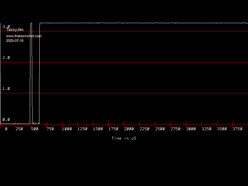 As a comparison, this is the same run captured on my CRO 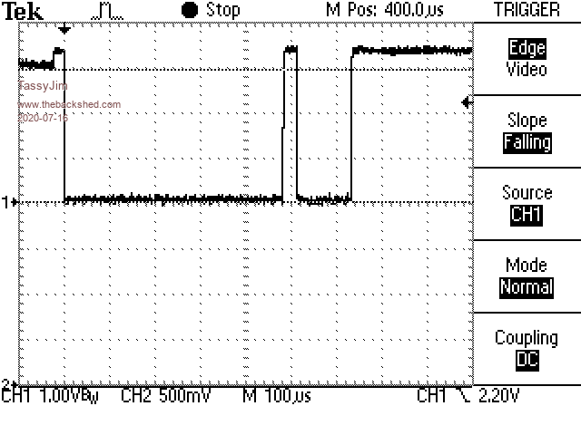 Jim VK7JH MMedit |
||||
| TassyJim Guru Joined: 07/08/2011 Location: AustraliaPosts: 6541 |
By changing the trigger to a normal TEMPR(42) read ADC OPEN 200000, 7,12,13,allDone ADC TRIGGER 1, -2 ' start reading when level drops below 2 ADC START presence() ' PIN(42) = 1 ' SETPIN 42, DOUT, OC ' PULSE 42, 0.481 ' change this value for testing ' SETPIN 42, DIN x = tempr(42) DO LOOP UNTIL INKEY$<>"" We get 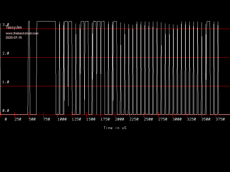 Not enough resolution to decode easily but enough to show that it works. I really do like the background ADC capture. Jim VK7JH MMedit |
||||
| matherp Guru Joined: 11/12/2012 Location: United KingdomPosts: 11588 |
Jim may well be correct in which case there is nothing to be done except try a higher value pullup - say 6K8 as a start. The low threshold for a STM32H743 is 0.4 * VDD - 0.1 so in our case 1.22V You could try the attached. I've set the timings to be exactly the same as the Arduino library CMM2V1.5.zip PS: Jim this is wonderful work you are doing and really shows off the CMM2 in new and interesting ways Edited 2020-07-16 17:23 by matherp |
||||
| Amnesie Guru Joined: 30/06/2020 Location: GermanyPosts: 757 |
So I have done some testing: first I ran Jims tests, here are my results: 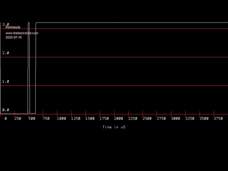 Then "By changing the trigger to a normal TEMPR(42) read" 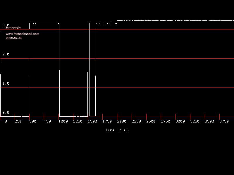 I've done all readings multiple times, the result is always stable and the same. After this I tested all kinds of pullups and even without pullup. Things got worse here. Without a pullup I only get error readings (1000) and with values up to 30k I get false readings like 16.120 (instead of 22�C) - so the pullup @ 4,7k seems to be right. After this I tested matherp's new firmware. But nothing has changed. The missreadings / errors in relation to the correct readings seems to be the same as before. So there are some correct readings, but a lot of errors, too. Just a reminder: the above readings from Jims test are done BEFORE FLASHING the firmware! It is really amazing how helpful and focused - all of you - are. I've never ever seen something similar on the internet. Wow! I think, I have to wait for the original ds18b20 sensor to arrive here. Greetings Daniel Edited 2020-07-16 20:33 by Amnesie |
||||
| robert.rozee Guru Joined: 31/12/2012 Location: New ZealandPosts: 2534 |
just a thought - are you able to hook the DS18B20 up to your arduino and get it outputting valid temperature readings, then use jim's (excellent) code to monitor JUST the data stream to see what it looks like when the sensor is working correctly? cheers, rob :-) |
||||
| The Back Shed's forum code is written, and hosted, in Australia. | © JAQ Software 2026 |
