
|
|
Forum Index : Microcontroller and PC projects : PicoMite V5.07.00b0 - beta firmware
| Author | Message | ||||
| Glen0 Senior Member Joined: 12/10/2014 Location: New ZealandPosts: 101 |
I'm in, thanks a lot Cheers |
||||
| Volhout Guru Joined: 05/03/2018 Location: NetherlandsPosts: 5994 |
OK, that took quite some time to get my backpack tracer program running again on the b2 release .... I used a variable called 'ADC'. And that coincides with the new ADC command, but did not give a message such as "syntax error". I would have expected that. But ADC = pin(ADC_pin) is perfectly accepted.. strange.... Anyway, here is the backpack tracer program adapted for pi-pico release V0.5.07b2 (sorry for the long listing). If you are not planning on building the hardware, a simple check can be done by adding a 10k resistor from GP18 (PWM1A) to GP26 (ADC0) and a 2.2nF capacitor from GP26 to GND. This is an elementary low pass filter. I have chosen these pins so I don't have to change the code to keep it compatible between MX170, F4, and pico. Only defines in the start of the program change. 'huntron '+-------------------------------------------------------------+ '| | '| BACKPACK TRACKER | '| | '| 21-7-2021 Volhout @ TheBackShed.com | '+-------------------------------------------------------------+ ' Curve tracer type huntron tracker ' For ILI9341 LCD backpack on 28 pin MX170 ' Uses pin 24 as analog input ' Uses pin 4 as pwm output ' Uses pin 9 and 10 to set amplifier gain ' all values scaled to 'resolution' ' there are 'samples' measurements per period '------------------------- Version History ------------------ ' V00 Proof of concept with 640 samples 100 resolution ' V01 Increase resolution to 1000, decrease samples to 200 ' V02 Implemented touch for REF and ZOOM buttons, REF added ' V03 Optimized main loop from 400msec to 300msec ' V04 Implemented support for HW zoom ' V05 Zoom implemented in SW ' V06 Restructure code to support samples and resolution as constants ' V07 Tune performance on MX170 ( 8 frames / second ) ' V08 Improved code for readability, remove obsolete DIM's ' V09 Screen resolution independent (untested), added header ' V10 Add dynamic measurement values ' V11 Support for ArmiteF4 (untested with hardware) ' V12 Support for PicoMite (MMbasic 0.5.07 alpha48) '------------------------------ init ------------------------ Option explicit init: If MM.Device$ = "ARMmite F407" Then 'STM32F407VET6 initialisation 'OPTION LCDPANEL ILI9341_16, LANDSCAPE 'TOUCH PB12, PC5 Const ADC_PIN = 15 ' 15/PC0 for F4 Const HI_GAIN_HI = 1 ' switch to high gain, PE2/pin1 for F4 Const HI_GAIN_LO = 5 ' switch to high gain, PE6/pin5 for F4 GUI interrupt Touch_Int ElseIf MM.Device$="RP2040 PicoMite" Then 'PicoMite initialisation 'option system spi gp2,gp3,gp4 'option lcdpanel ili9341,landscape,gp7,gp6,gp5 'option touch cs,irq,beep - not tested Const ADC_PIN = 31 'GP26 Const HI_GAIN_HI = 32 'GP27 Const HI_GAIN_LO = 34 'GP28 SetPin 24,PWM1A 'GP18 Else 'PIC32MX170 initialisation 'OPTION LCDPANEL ILI9341, L, 2, 23, 6 'OPTION TOUCH 7, 15 CPU 48 ' max speed - not needed in ARM F4 Const ADC_PIN = 24 ' 24 for MX170 Const HI_GAIN_HI = 10 ' switch to high gain, 10 for MX Const HI_GAIN_LO = 9 ' switch to high gain, 9 for MX ' enable touch SetPin 15, INTL, Touch_Int EndIf 'start board SetPin ADC_PIN,ain ' voltage input ADC1-ch10 (at pin 15) PWM 1,120000,50 ' set PWM to 50% (0Vdc amplifier out) ' pin 31/PA6 on F4, pin 4 on MX170 amp_high_gain ' set amplifier gain ' Define samples each scan Const samples = 64 Const resolution = 1000 ' external ADC divider (R15=47k into R10=12k//R11=15k) Const R10_R11 = 12000*15000/(12000+15000) Const resistor_divider = (47000 + R10_R11)/R10_R11 ' Declare variables ------------------------------------------------- ' Declare defaults for scaling ADC to 'resolution', these values ' are fine tuned in calibration (at powerup) Dim integer lowgain=resolution/3.3, highgain=2*lowgain Dim gain=lowgain Dim integer lowoffset=0, highoffset=-resolution/2 Dim offset=lowoffset ' for user interface, xt/yt are touch coordinates Dim integer xt,yt ' generic i,j,h are counters, ADC is scaled adc value, adc10 and adc90 ' are used in calibration Dim integer i,j,h,ADCV Dim float adc10,adc90 ' display waveform, x/y are measured waveform, xr/yr are memory reference Dim integer x0,y0,x(samples),y(samples),xr(samples),yr(samples) ' init coordinates with values that fit the screen For i=1 To samples xr(i)=MM.HRes-3:yr(i)=MM.VRes/2:x(i)=MM.HRes-3:y(i)=MM.VRes/2 Next i x0=MM.HRes-3:y0=MM.VRes/2 ' display numerics, xnl/ynl for left side, xnr/ynr for right side Dim integer xnr=100,xnl=100,ynr=100,ynl=100,yor=0,yol=0 Dim float vr,ir,vl,il ' generate waveform, pw = pwm value, pc = pwm value scaled to 'resolution' Dim pw(samples), pc(samples) ' fill waveform with triange wave 0...100% For i=1 To samples / 2 pw(i) = 100 - ( 200 / samples ) * i pc(i) = resolution * pw(i) / 100 pw(i + samples / 2) = ( 200 / samples ) * i pc(i + samples / 2) = resolution * pw(i + samples / 2) / 100 Next ' graphics scaling to resolution Dim float Vstep = MM.VRes / resolution, Hstep = MM.HRes / resolution Dim center = resolution / 2 ' buttons and line colors Dim integer membuttoncolor = RGB(blue), zoombuttoncolor = RGB(blue) Dim integer memcolor = RGB(black), linecolor = RGB(yellow) 'debug Memory ' initialize screen draw_window ' timed interrupts SetTick 1000, Time_Int, 1 ' calibrate analog circuits calibrate '------------------------------ MAIN ------------------------ main: ' all comments removed from main loop to speed it up ' cycle through all pwm values using pointers i (actual) and j (last) ' erase last segment ' allways draw memory line, but color decides if it is visible ' draw memory line first so actual overwrites memory ' measure input value ' recalculate new segment (huntron method) ' draw new segement Do Timer = 0 For i = 1 To samples j = i - 1 : If j = 0 Then j = samples PWM 1,120000,pw(i) Line x0,y0,x(i),y(i),1,0 Line xr(j),yr(j),xr(i),yr(i),1,memcolor x0 = x(i) : y0 = y(i) ADCV = (Pin(ADC_PIN) * gain) + offset y(i)=(ADCV - pc(i) + center) * Vstep x(i)= ADCV * Hstep Line x(j),y(j),x(i),y(i),1,linecolor Next i Print Timer Loop '--------------------------- SUBS --------------------------- Sub Touch_Int xt = Touch(x) : yt = Touch(y) 'check for MEM button if we should display memory If xt < ( MM.HRes / 4 ) And yt < ( MM.VRes / 4 ) Then If memcolor = RGB(black) Then For h = 1 To samples 'copy live to REF line yr(h) = y(h) xr(h) = x(h) Next memcolor = RGB(red) membuttoncolor = RGB(red) Else memcolor = RGB(black) membuttoncolor = RGB(Blue) EndIf RBox 10,10,60,30,2,RGB(white),membuttoncolor Text 30,18,"MEM",,,,RGB(white),membuttoncolor EndIf 'check for ZOOM button to see if we should zoom in If xt > (3 * MM.HRes / 4 ) And yt > (3 * MM.VRes / 4) Then If zoombuttoncolor = RGB(blue) Then zoombuttoncolor = RGB(red) adc_high_gain amp_low_gain Else zoombuttoncolor = RGB(Blue) adc_low_gain amp_high_gain EndIf RBox MM.HRes-70,MM.VRes-40,60,30,2,RGB(white),zoombuttoncolor Text MM.HRes-55,MM.VRes-32,"ZOOM",,,,RGB(white),zoombuttoncolor EndIf draw_frame Pause 300 'prevent double touch End Sub Sub amp_high_gain SetPin HI_GAIN_LO,dout : Pin(HI_GAIN_LO)=0 SetPin HI_GAIN_HI,dout : Pin(HI_GAIN_HI)=1 End Sub Sub amp_low_gain SetPin HI_GAIN_LO,din SetPin HI_GAIN_HI,din End Sub Sub adc_high_gain gain = highgain offset = highoffset End Sub Sub adc_low_gain gain = lowgain offset = lowoffset End Sub Sub draw_window 'clear screen CLS 'draw outside lines draw_frame 'draw buttons RBox 10,10,60,30,2,RGB(white),membuttoncolor Text 30,18,"MEM",,,,RGB(white),membuttoncolor RBox MM.HRes-70,MM.VRes-40,60,30,2,RGB(white),zoombuttoncolor Text MM.HRes-55,MM.VRes-32,"ZOOM",,,,RGB(white),zoombuttoncolor End Sub Sub calibrate 'calibrate standard mode ------------ amp_high_gain adc_low_gain 'measure 10% and 90% points PWM 1,120000,10 Pause 1 adc10 = Pin(ADC_PIN) PWM 1,120000,90 Pause 1 adc90 = Pin(ADC_PIN) 'calculate ADC low gain and offset lowgain = 80 * resolution / (100 * (adc90 - adc10)) lowoffset = - lowgain * (adc10 - ((adc90 - adc10)/8)) Print adc10, adc90, lowgain , lowoffset 'calibrate zoom mode -------------- amp_low_gain adc_high_gain 'measure 10% and 90% values PWM 1,120000,10 Pause 1 adc10 = Pin(ADC_PIN) PWM 1,120000,90 Pause 1 adc90 = Pin(ADC_PIN) 'calculate ADC high gain and offset highgain = 80 * resolution / (100 * (adc90 - adc10)) highoffset = - highgain * (adc10 - ((adc90 - adc10)/8)) Print adc10, adc90, highgain , highoffset 'back to standard mode amp_high_gain adc_low_gain End Sub Sub draw_frame 'draw outside lines Line 1,1,1,MM.VRes-2,2,RGB(white) Line 1,MM.VRes-2,MM.HRes-2,MM.VRes-2,2,RGB(white) Line MM.HRes-2,MM.VRes-2,MM.HRes-2,1,2,RGB(white) Line MM.HRes-2,1,1,1,2,RGB(white) End Sub Sub Time_Int 'check if left marker needs update If ynl <> y(samples/2) Then 'erase old text Text xnl+12,ynl+yol," ",l,,,0,0 'write markers Box xnl-5,ynl-5,10,10,,0 ' calculate voltage xnl = x(samples/2): ynl = y(samples/2) vl = resistor_divider * ((xnl - MM.HRes / 2) / Hstep) / gain ' repair corrupted frame draw_frame 'write markers Box xnl-5,ynl-5,10,10,,RGB(cyan) 'get new coordinates for writing text, and write If ynl > MM.VRes-30 Then yol=-20 Else yol=5 Text xnl+12,ynl+yol,Str$(vl,0,2)+"V",l,,,RGB(white),0 EndIf ' check if right marker needs an update If ynr <> y(samples) Then 'erase old text Text xnr-12,ynr+yor," ",r,,,0,0 'write markers Box xnr-5,ynr-5,10,10,,0 ' calculate voltage xnr = x(samples): ynr = y(samples) vr = resistor_divider * ((xnr - MM.HRes / 2) / Hstep) / gain ' repair corrupted frame draw_frame 'write markers Box xnr-5,ynr-5,10,10,,RGB(cyan) 'get new coordinates for writing text, and write If ynr < 30 Then yor=5 Else yor=-20 Text xnr-12,ynr+yor,Str$(vr,0,2)+"V",r,,,RGB(white),0 EndIf End Sub Edited 2021-07-21 17:15 by Volhout PicomiteVGA PETSCII ROBOTS |
||||
| matherp Guru Joined: 11/12/2012 Location: United KingdomPosts: 11636 |
V5.07.00b4 PicoMiteV5.07.00b4.zip Includes pullups on UART RX pins Fixes bug in READ comamnd when using individual array elements (bug introduced in b3) Generates error when ADC used as variable name Edited 2021-07-22 03:38 by matherp |
||||
| Glen0 Senior Member Joined: 12/10/2014 Location: New ZealandPosts: 101 |
Greenhorn question.. I'm trying to load a simple program into a picomite running b4. It has nothing connected (no SD Card or LCD etc) after loading the program I get; "ERROR: SDcard not configured" > > Failed to start Saving program Can I run a pico without an SD card and if so what do I need to do so that I don't get that error. (I haven't successfully loaded any programs into a Pico yet. I have only ever been using micromites.) |
||||
| matherp Guru Joined: 11/12/2012 Location: United KingdomPosts: 11636 |
Yes More information needed. How are you trying to load the program? If your are using MMEdit you have got the protocol wrong (don't use CMM2 or CMM) Edited 2021-07-22 18:31 by matherp |
||||
| Glen0 Senior Member Joined: 12/10/2014 Location: New ZealandPosts: 101 |
Connected with MMEdit and I'm just trying to do a simple A/D conversion on pin 31 and print it to MM Chat. Thanks |
||||
| Glen0 Senior Member Joined: 12/10/2014 Location: New ZealandPosts: 101 |
Sorry, Just re-read your reply and realised I am using the CMM 2 Chat. I will see what other options there are. |
||||
| matherp Guru Joined: 11/12/2012 Location: United KingdomPosts: 11636 |
On the dropdown in MMEDit choose Micromite+ 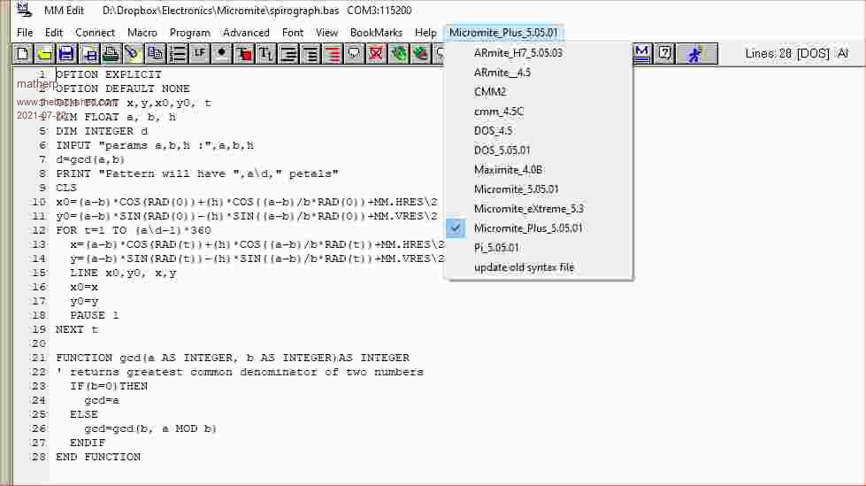 |
||||
| Glen0 Senior Member Joined: 12/10/2014 Location: New ZealandPosts: 101 |
Much appreciated, I got as far as Micromite 5.05.01 which was more successful, but still had a count argument complaint. I will use your suggestion this weekend if I get a bit of spare time. Looking forward to getting it going. |
||||
| lizby Guru Joined: 17/05/2016 Location: United StatesPosts: 3811 |
Since the picomite lacks the SERVO command which all of the other micromites have (I think) except DOS, do you think it would be good to add info about the PWM command which can be used to control a standard servo to the documentation? Peter said the PWM range is between 5 and 10, so, for instance, for pin 25, GP19: setpin 25,pwm1b pwm 1,50,,5+(servo_position_in_percent_of_full_scale)*0.05 This code works--20 steps from full counter-clockwise to full clockwise and back in 100ms steps. SetPin 25,pwm1b do For j=1 To 40 If j < 21 Then PWM 1,50,,5+j*.25 ' swing clockwise Print 5+j*.25;" "; Else PWM 1,50,, 10-(j-20)*.25 ' swing counter-clockwise Print 10-(j-20)*.25;" "; EndIf Pause 100 Next j loop PicoMite, Armmite F4, SensorKits, MMBasic Hardware, Games, etc. on FOTS |
||||
| Mixtel90 Guru Joined: 05/10/2019 Location: United KingdomPosts: 8964 |
Done, lizby. :) Latest version: PicoMite Beta docs 00b1.zip It's getting a little large, I suppose, but I doubt if it'll get a lot bigger now. Mick Zilog Inside! nascom.info for Nascom & Gemini Preliminary MMBasic docs & my PCB designs |
||||
| matherp Guru Joined: 11/12/2012 Location: United KingdomPosts: 11636 |
V5.07.00b5 This version now allows you to use different pins for the SPI for the SDcard and the LCD/TOUCH OPTION SDCARD CSpin [,CLKpin, MOSIpin, MISOpin] If the optional pins are not specified the SDcard will use the pins specified by OPTION SYSTEM SPI NB: the pins specified by OPTION SYSTEM SPI must be a valid set of H/W SPI pins (SPI0 or SPI1), however, the pins specified by OPTION SDCARD can be any pins. Obviously the pins specified by OPTION SYSTEM SPI and OPTION SDCARD can't be the same. The reason for the change is to increase flexibility and allow the use of some of the Waveshare display boards for the Pico that use different pins for the two functions. This beta version completes all my outstanding functional enhancements and subject to further testing will become the first release candidate |
||||
| Mixtel90 Guru Joined: 05/10/2019 Location: United KingdomPosts: 8964 |
is the SD card speed option still valid, Peter? Mick Zilog Inside! nascom.info for Nascom & Gemini Preliminary MMBasic docs & my PCB designs |
||||
| matherp Guru Joined: 11/12/2012 Location: United KingdomPosts: 11636 |
No: the SDcard is now always bitbanged for reliability |
||||
| Mixtel90 Guru Joined: 05/10/2019 Location: United KingdomPosts: 8964 |
I thought it was. I've not checked the latest betas, but 00b1 was still showing it on OPTION LIST. Mick Zilog Inside! nascom.info for Nascom & Gemini Preliminary MMBasic docs & my PCB designs |
||||
| Volhout Guru Joined: 05/03/2018 Location: NetherlandsPosts: 5994 |
Servo always has been a strange thing in control languages. This is partly because the RC servo's had brand specific specification. The Graupner servo's had a mid position of 1.5ms rotating CW The Robbe/Futaba servo's also had a 1.5ms mid position but rotate CCW The Multiplex servo's had a 1.6ms mid position rotatin CW Of coarse the gains (angle change per ms) was different, as was the operating range of the PWM input. Currently servo's have a mid position of 1.5ms, and they operate +/- 60 degrees between 1ms and 2ms. Generally the operating range is 0.75ms....2.25ms, allowing the servo's to rotate -90/+90 degrees maximum. 1/ This is what is implemented in the PICAXE basic, where you set the servo in degrees (actually 0...180 degrees) 2/ In MMBasic you program the servo in ms. There is technically no limitation, so you can rotate the servos to positions that are beyond it's control. If we include an example routine in our documentation how to control servo's with using PWM, I suggest to use one of the above definitions. A simple mathmatical formula that either converts degrees to %, or ms to %. For MMbasic formula: simply multiply with 5 /for a servo connected to PWM1A, tested on CMM2 SERVO_MS! = 1.5 'value in ms PWM 1,50,SERVO_MS!*5 Those are my 5 ct.... Volhout P.S. what is agains simply adding the servo command ? Do we exceed 256 commands ? Edited 2021-07-23 05:19 by Volhout PicomiteVGA PETSCII ROBOTS |
||||
| Mixtel90 Guru Joined: 05/10/2019 Location: United KingdomPosts: 8964 |
I know nothing whatsoever about servos. I've never even handled one. If anyone wishes me to add servo stuff to the doc I'm afraid they are going to have to tell me *exactly* what they want. I'm not going to guess on this one. :) It appears to me that the PWM system is far more flexible than any SERVO command could be. What you need are some standard subroutines that can be used to suit whatever limits you want for particular servos. But then, what would I know? :) Edited 2021-07-23 05:21 by Mixtel90 Mick Zilog Inside! nascom.info for Nascom & Gemini Preliminary MMBasic docs & my PCB designs |
||||
| thwill Guru Joined: 16/09/2019 Location: United KingdomPosts: 4378 |
Hi Peter, The PicoMite seems to be limited to 64 Functions/Subs ? Is this a hard limit or something the code has inherited from earlier Micromites and could be upped ? Fingers crossed it is the latter otherwise it rather kibosh's my attempt to get my unit-tests and SAAINT running on the PicoMite  . .Best wishes, Tom MMBasic for Linux, Game*Mite, CMM2 Welcome Tape, Creaky old text adventures |
||||
| panky Guru Joined: 02/10/2012 Location: AustraliaPosts: 1132 |
Hi All, Beta 5 does not come up as a link for me - anyone else have this problem? Doug. ... almost all of the Maximites, the MicromMites, the MM Extremes, the ArmMites, the PicoMite and loving it! |
||||
palcal Guru Joined: 12/10/2011 Location: AustraliaPosts: 2039 |
Yes, I noticed that earlier, was waiting for someone else to confirm. "It is better to be ignorant and ask a stupid question than to be plain Stupid and not ask at all" |
||||
| The Back Shed's forum code is written, and hosted, in Australia. | © JAQ Software 2026 |
