
|
|
Forum Index : Microcontroller and PC projects : Silly idea for a new (old) MMBasic port
| Author | Message | ||||
| Mixtel90 Guru Joined: 05/10/2019 Location: United KingdomPosts: 8904 |
Can't see why XMODEM and AUTOSAVE wouldn't be retained as they are pretty integral to MMBasic now. Mick Zilog Inside! nascom.info for Nascom & Gemini Preliminary MMBasic docs & my PCB designs |
||||
| CaptainBoing Guru Joined: 07/09/2016 Location: United KingdomPosts: 2171 |
100% |
||||
| scruss Regular Member Joined: 20/09/2021 Location: CanadaPosts: 97 |
I've been using these for a while with MicroPython. They're decent enough (extremely decent if you add extra flash) but they're 2/3 the speed of the F407 in board used in the Armmite. I got mine from Universal Solder in Windsor, Canada. They're no longer as cheap as they were: availability of many of the STM32s is getting very tough. The pins are pretty heavily muxed on the F411 boards. I completely hosed the external flash in one of mine by accidentally hooking up some Neopixels on the same SPI interface. |
||||
| flasherror Senior Member Joined: 07/01/2019 Location: United StatesPosts: 159 |
1. Anyone have a confirmed correct schematic for the board in Peter's photo? I found one at https://stm32-base.org/assets/pdf/boards/original-schematic-STM32F411CEU6_WeAct_Black_Pill_V2.0.pdf 2. Does this board have a diode between USB and 5V so that there are no issues powering the board from a non-USB source and plugging in a USB cable? I believe the earlier Blue Pill board didn't have this diode, making it difficult to use the board in real world applications (where you have supplied 5V from an external source to the device's 5V pin). I found https://stm32-base.org/boards/STM32F411CEU6-WeAct-Black-Pill-V2.0.html which indicates that "The +5V pins on this board are directly connected to the +5V pin of the USB connector. There is no protection in place. Do not power this board through USB and an external power supply at the same time." I guess one can power the board via the 5V header pin through a diode to prevent USB 5v from "saying hello" to the external 5V? |
||||
| matherp Guru Joined: 11/12/2012 Location: United KingdomPosts: 11499 |
Assuming I go ahead, this port will not use USB so you can either use a USB-C supply (e.g. Raspberry Pi)or connect to the 5V pin. There is no reason that you would use both |
||||
| Mixtel90 Guru Joined: 05/10/2019 Location: United KingdomPosts: 8904 |
Black Pill supplies: There are two 5V input pins on the Black Pill board. They are linked. The 5V rail feeds a regulator (U2) to get 3.3V. There is no way to disable it as the EN pin is wired high. This 3.3V feeds the processor (U1) and VBAT (on U1) via a diode, VBAT is also fed from the VB pin via a second diode to allow for an external battery to keep the RTC running. So yes, you can have 2 sources of supply, but one is a battery for the RTC. :) matherp: I thought the Black Pill supported flash load via a uf2 file, Peter? Wouldn't you be using that for firmware updates over USB? I don't suppose it matters whether programming is via USB or a USB/TTL adapter. Mick Zilog Inside! nascom.info for Nascom & Gemini Preliminary MMBasic docs & my PCB designs |
||||
| flasherror Senior Member Joined: 07/01/2019 Location: United StatesPosts: 159 |
I first thought the USB would be used as the console, but if USB remains unused then I guess potential 5V contention would not be an issue, unless it is externally powered by 5V header pin and then I plug in a USB cable because I forgot the console isn't on USB  |
||||
| flasherror Senior Member Joined: 07/01/2019 Location: United StatesPosts: 159 |
I'm not too worried about the 3.3V, as the 5V > 3.3V regulator takes care of that, but concerned about externally powering 5V via the header 5V pins and then plugging in a USB cable. This would connect external 5V to USB 5V which neither would like. |
||||
| Mixtel90 Guru Joined: 05/10/2019 Location: United KingdomPosts: 8904 |
That might indeed introduce a "flash error" - one that stops the USB port on your computer from working! Not the greatest idea. Mick Zilog Inside! nascom.info for Nascom & Gemini Preliminary MMBasic docs & my PCB designs |
||||
| matherp Guru Joined: 11/12/2012 Location: United KingdomPosts: 11499 |
No: a bin file same as CMM2. The USB will be used for that but not by MMBasic itself |
||||
| Mixtel90 Guru Joined: 05/10/2019 Location: United KingdomPosts: 8904 |
Ah, thanks. I really should look more closely at this board. Circuits, I'm happy with. Firmware is something else. :) Mick Zilog Inside! nascom.info for Nascom & Gemini Preliminary MMBasic docs & my PCB designs |
||||
| flasherror Senior Member Joined: 07/01/2019 Location: United StatesPosts: 159 |
Forgot to ask: Is there a reason USB will not be supported? If you do decide to proceed thanks in advance (and I'm sure I'm not the only one with that sentiment). Thoughts: While the Armite F407 is a nice board the Black Pill 411 chip module is probably easier to design with, being smaller and male headers (fits on breadboard) compared to the larger and "upside down host board mating" for the F407 (or using ribbon cables). Can you compare what program/RAM sizes for the 411 might be? (trying to figure out where in the *mite ecosystem this fits into compared to MX170, Pico, etc). |
||||
| flasherror Senior Member Joined: 07/01/2019 Location: United StatesPosts: 159 |
LOL. I don't understood why there isn't a jumper to disconnect 5V from the USB Vbus 5V, as it seems to me that this would be a simple solution if you're externally powering 5V and then plug USB cable in. Jumper not installed = USB can't supply 5V. |
||||
| Mixtel90 Guru Joined: 05/10/2019 Location: United KingdomPosts: 8904 |
Probably cost and/or board space. If you want to keep USB plugged in make a special lead with +5 snipped and a schottky diode inserted. It won't stop it working as a normal lead but will protect your USB port. Mick Zilog Inside! nascom.info for Nascom & Gemini Preliminary MMBasic docs & my PCB designs |
||||
| matherp Guru Joined: 11/12/2012 Location: United KingdomPosts: 11499 |
Progress 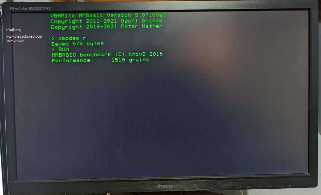 |
||||
| lizby Guru Joined: 17/05/2016 Location: United StatesPosts: 3782 |
Bravo. Compared to Picomite: MMBASIC grain benchmark (C) KnivD 2016 Performance: 2033 grains PicoMite, Armmite F4, SensorKits, MMBasic Hardware, Games, etc. on FOTS |
||||
| gadgetjack Senior Member Joined: 15/07/2016 Location: United StatesPosts: 233 |
This will look great! I found my board and excited to try this. |
||||
| Mixtel90 Guru Joined: 05/10/2019 Location: United KingdomPosts: 8904 |
For some reason I read that as the VEGemite version, which would no doubt please the Australian contingent ... :) Nice work, Peter. :) Just musing: the pcb should perhaps have a link to allow the user to select green, amber or white phosphor display by selecting suitable resistors. I wonder if the VGA routine could produce scan lines? Hmmm... Perhaps that's going a bit too far. Edited 2021-11-22 18:43 by Mixtel90 Mick Zilog Inside! nascom.info for Nascom & Gemini Preliminary MMBasic docs & my PCB designs |
||||
| thwill Guru Joined: 16/09/2019 Location: United KingdomPosts: 4369 |
We should definitely promote mispronouncing the name and calling it the "VeGAmite". Peter, I suspect I have misunderstood but in an earlier post you said "this port will not use USB", does that mean it will have no serial console (so no AUTOSAVE or XMODEM ?) and no SD card ... how are we supposed to transfer software to this except by banging it out at the keyboard ?  Neither sounds like going to far to me, sounds cool if it is "easy". Neither sounds like going to far to me, sounds cool if it is "easy".Best wishes, Tom Edited 2021-11-22 19:37 by thwill MMBasic for Linux, Game*Mite, CMM2 Welcome Tape, Creaky old text adventures |
||||
| matherp Guru Joined: 11/12/2012 Location: United KingdomPosts: 11499 |
Did you look at the picture? It will have a standard serial console on a uart. The USB is not usable because the chip can't generate the 48MHz clock needed for USB at the same time as the 25.175MHz clock needed for VGA. Only the H series chips have multiple clocks that allow this (like on the CMM2) |
||||
| The Back Shed's forum code is written, and hosted, in Australia. | © JAQ Software 2026 |
