Notice. New forum software under development. It's going to miss a few functions and look a bit ugly for a while, but I'm working on it full time now as the old forum was too unstable. Couple days, all good. If you notice any issues, please contact me.
mab1 Senior Member Joined: 10/02/2015 Location: United KingdomPosts: 282
Posted: 01:04am 09 Sep 2023
Copy link to clipboard
Print this post
Cheers . Oh i see - hence baud c i wanted to double check rather than assuming that it wouldn't affect the mppt. I needed baudc>90 at 20kHz and 120 at 40kHz. But I must confess, since i asked the question i've come full circle: it seemed i ought to be able to drive the vfd directly instead of using a nano as an interpreter from 9600 serial to 9600 serial, so I've been modding the code to do inverted logic (actually as easy in practice as it was in theory) ; then modding the do_data sub to include the origin and LF/CR commands. End result is that the mppt drives the vfd directly without an extra nano, and the baudc can go back to its original 50.
I have learned a lot about C programming since i built this mppt- and inductor design - the C code is actually making sense when reading the program now - mostly.
I'm still experimenting with different delays and tweaks in the mppt scan, (when not distracted by work or playing with vfds): if i slow the mppt_scan a bit it does hold onto the MPP better, down to Iout < 10A, but still seems to drop to too low a voltage as Iout drops down in single figures. Slowing the scan further helps but then the scan is taking a VERY long time.
Still experimenting to figure how to make it hold on down to 10's of watts without 'cheating ' (i.e. limiting the scan range) or spending unreasonable amounts of time scanning. All good fun
mab1 Senior Member Joined: 10/02/2015 Location: United KingdomPosts: 282
Posted: 09:58pm 09 Sep 2023
Copy link to clipboard
Print this post
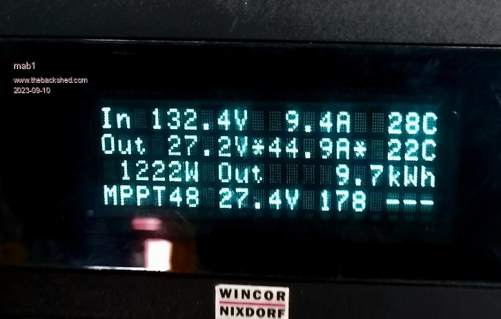
New power record : didn't notice til after i took the pic that it's actually nudging I_max.
1245w in 1222w out makes 98% efficiency, though i suspect uncertainty in the calibrations are > 2% Edited 2023-09-10 08:05 by mab1
poida Guru Joined: 02/02/2017 Location: AustraliaPosts: 1480
Posted: 03:40am 10 Sep 2023
Copy link to clipboard
Print this post
this is great to see.
I like the low choke temperature of 28C, this indicates very small losses from it.
The star preceding the 44.9A means the output voltage or battery voltage is within 0.2V of ABSORB voltage
The star after 44.9A means it's limiting output current to 45A.
I would feel comfortable with increasing the output current limit to 55A, based on the low temperatures. You could set up the over temp throttle a bit aggressive to wind back output current quickly should the heat sink get too warm. ("4 - H.S. throttle low" from the menu)
I agree the efficiency is a bit high and is likely a little less than that but I would not complain about this at all!wronger than a phone book full of wrong phone numbers
Bryan1 Guru Joined: 22/02/2006 Location: AustraliaPosts: 2138
Posted: 06:43am 10 Sep 2023
Copy link to clipboard
Print this post
Well done Mab good to see you got there and the results are there to see.
Cheers Bryan
mab1 Senior Member Joined: 10/02/2015 Location: United KingdomPosts: 282
Posted: 12:06am 11 Sep 2023
Copy link to clipboard
Print this post
Thanks
Alas the low choke temp was due to it being only just powered up after uploading 'new' software (due to an error in my software mod that made it stay in night mode - i still have a lot to learn about programming in C ). It would normally be up above 65C if sustaining that current.


 . Oh i see - hence baud c
  i wanted to double check rather than assuming that it wouldn't affect the mppt. I needed baudc>90 at 20kHz and 120 at 40kHz. But I must confess, since i asked the question i've come full circle: it seemed i ought to be able to drive the vfd directly instead of using a nano as an interpreter from 9600 serial to 9600 serial, so I've been modding the code to do inverted logic (actually as easy in practice as it was in theory)
  ; then modding the do_data sub to include the origin and LF/CR commands. End result is that the mppt drives the vfd directly without an extra nano, and the baudc can go back to its original 50.
 : didn't notice til after i took the pic that it's actually nudging I_max.