
|
|
Forum Index : Microcontroller and PC projects : MX170 PCB Layout single sided
| Author | Message | ||||
| MicroBlocks Guru Joined: 12/05/2012 Location: ThailandPosts: 2209 |
I hope I am not a nuisance but I see some small ways to improve upon it. Place header pins for pin 19 and 20. (On second thought just leave out pin 20 because it is really only for the capacitor and might introduce noise.) Move the capacitor for these pins up a little and rotate 90 degrees. I think it will fit. Also header pins for pin 27 and 28. You could then also add a header pin for the 5v. Both sides would then have 15 pins, allowing access to all pins and have power. You could then use this as a connector for a mini shield. I could think of a USB-serial and a ICSP mini shield for programming purposes and maybe a rtc mini shield or fram etc... :) Microblocks. Build with logic. |
||||
Grogster Admin Group Joined: 31/12/2012 Location: New ZealandPosts: 9964 |
OK, try this one on for size: 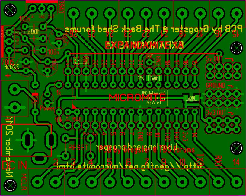
I have allowed for either SMD or leaded MLC cap for Vcap. Extra headers added. Can we squeeze anything else in? @ centrex: I will be posting the gerbers once everyone is happy. I will also be getting some made, so members can get them from me if they want one, but don't want to bother etching their own one. Any board(s) I supply, would have a SMD 10uF MLC ceramic fitted for Vcap. EDIT: Swapped two leaded 100n's for SMD versions. It's neater, and not so "Tight". Any boards I supply will have the three SMD parts fitted for you, so all you have to do, is all the other thru-hole parts. Smoke makes things work. When the smoke gets out, it stops! |
||||
| MicroBlocks Guru Joined: 12/05/2012 Location: ThailandPosts: 2209 |
A few more suggestions. I hope you see the value in it, because it comes down to personal preferences and yours are probably different then mine. So ignore if its not valuable for you. :) I would change the resistors placement slightly so that they can be mounted flat. Having the resistors stand up right next to the connector will interfere with something you plug in. This is also the case for the cap on pin 19/20. Furthermore having a small 'sea of holes' can be very handy for those small addons that always seems to happen. Smaller power strips for 5v and 3.3v both with their own ground strip. I made a crude paint version of your pcb with the modifications encircled with blue. 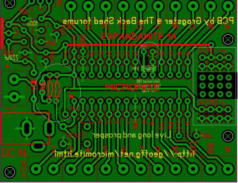
Microblocks. Build with logic. |
||||
| Grogster Admin Group Joined: 31/12/2012 Location: New ZealandPosts: 9964 |
Nice thinking - will make the changes. Stay tuned.... EDIT: OK, how about this? 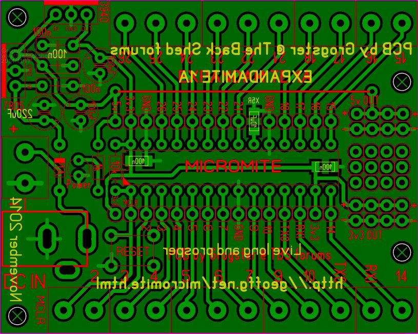
Smoke makes things work. When the smoke gets out, it stops! |
||||
| MicroBlocks Guru Joined: 12/05/2012 Location: ThailandPosts: 2209 |
Yes. Those smd caps solve some placement problems and the 1210's are easy to solder. Looking at the t-blocks I see there is no regulated power available from them! I think you should need at least one GND on a t-blocks. Don't know how to solve that problem without making the PCB bigger.:( What are the current dimensions? Are the outer t-blocks island on the same grid as the connectors next to the mcu? Microblocks. Build with logic. |
||||
| Grogster Admin Group Joined: 31/12/2012 Location: New ZealandPosts: 9964 |
T-block on left of PCB has ground connection. Really is no need, as far as I am concerned, for regulated power at the T-blocks. You have 5v + GND and 3v3 + GND strips to tap into, and also 5v, 3v3 and GND points on the headers down either side of the chip. PCB size is 69mm x 55mm. T-blocks and connectors next to MCU are on a 0.3175mm grid. Smoke makes things work. When the smoke gets out, it stops! |
||||
| MicroBlocks Guru Joined: 12/05/2012 Location: ThailandPosts: 2209 |
The reason for regulated power on a t-blocks is that if you made another module those voltages would be available. Sure you can take it from the pin headers but if you want to use the PCB in rougher environments, like in a car, vibration is your biggest enemy. T-blocks are a good way to minimize that problem. If that is one of the environments you want to use it in it might be good to drop the 3.3v and 5v headers and put a t-blocks in its place. It really all depends in what scenarios it will be used. I often have to fit things in cars so I am thinking along that scenario. 69x55 is very compact. A double sided PCB would not be smaller. I have a cnc, so this would be a great test to see how it comes out. (if only a day had 48 hours....) Great job squeezing everything in.:) Microblocks. Build with logic. |
||||
| atmega8 Guru Joined: 19/11/2013 Location: GermanyPosts: 738 |
I want my PCF8563 ;-((( MMBASIC supports it directly with its TIME$/DATE$.. For me this is a Basic component and Function which should also exist on a Basic PCB ;-)...lot's of effort for Geoff, so don't deny it;-) Give it a Chance... All 4 parts would fit in the right upper Corner, near to I2C pins 18/17. DIL8, Lithium Socket, Crystal and Trimmer ore fix capacitor. The 100 nf on the right side can be shiftet a Little bit to the left, so the I2C Pins of the pic get accessible. |
||||
| Grogster Admin Group Joined: 31/12/2012 Location: New ZealandPosts: 9964 |
@ TZA: I could replace the 3v3, 5v and ground header strips with T-blocks for regulated voltage output via T-blocks. You would lose the small sea-of-holes in the process. Thoughts? @ atmega8: I will shoehorn a couple of pins in for the I2C. 
EDIT: On second thoughts, I won't. Pins 17 and 18 are I2C, and they are accessible via the pin-strips either side of the chip. These strips are on a 0.3175mm grid, 15.240mm apart, so it would be dead easy to design a daughter-board to directly plug into the headers that will contain your RTC or other stuff. 3v3, 5v and GND are also available via these headers. Smoke makes things work. When the smoke gets out, it stops! |
||||
centrex Guru Joined: 13/11/2011 Location: AustraliaPosts: 320 |
Hi Grogster Your measurements puzzle me, surely the pin headers, ic sockets etc are on a 0.1 inch or 2.5mm spacing. All components were once apon a time until we were all metricated were made to a standard 0.1 inch pitch and still are. It is a good looking board best you call it quits as it will be never ending. Cliff Cliff |
||||
| Grogster Admin Group Joined: 31/12/2012 Location: New ZealandPosts: 9964 |
Hi Cliff. The PIC32 and headers are all standard 0.1"/2.54mm pin spacing, but the underlying grid is 0.3175mm, in order to squeeze everything in, and still allow for neat track layout. So, if you use a 2.5 grid, you WILL NOT be able to design a daughter-board to fit. However, if you use a 0.3175 grid, you will have no problems at all with spacing. All PCB layout software allows you to change the grid size, and most of them let you change it on the fly. Standard practise is to stick to one grid size, but in this case, I have changed grid sizes depending on what I needed to factor in. However, the PIC32 chip, and the header strips either side, are on a common grid - that being 0.3175mm. Example: 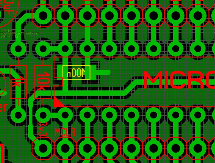
As to closing it off now, you are probably right in that respect! 
Unless someone else comes up with a very obvious ommision on my design, we'll call it final for the alpha-1 version. I will wait till tonight to see if anyone else chimes in with their thoughts. Once closed, I will upload the ZIP, which will contain the gerbers, the GIF's, Excellon drill data and isolation milling files, for those with a CNC. I will also be getting some done at Itead, so anyone interested in that option(not having to make their own one), please flick me a PM. As mentioned earlier, any boards I supply will have the three SMD parts fitted, so all the builder needs to do, is source the rest of the thru-hole parts and build it.(builders need not worry about the SMD - the board will be supplied with those parts pre-fitted) Smoke makes things work. When the smoke gets out, it stops! |
||||
bigmik Guru Joined: 20/06/2011 Location: AustraliaPosts: 2981 |
Grogs, As for the PCF8563 (which IMHO is turning your board into something you didnt intend it for and Single sided is a bit much to expect), However A simple addition of 3 pads (with no other track modification) as shown in the white box here: 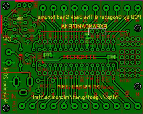
Would enable a PCF8563 plug in module similar to This One To simply plug in (skipping the Vcc line which should be unnecessary due to the battery) Regards, Mick PS. It also allows a connection to other I2C devices if the module isnt needed. Mik Mick's uMite Stuff can be found >>> HERE (Kindly hosted by Dontronics) <<< |
||||
| centrex Guru Joined: 13/11/2011 Location: AustraliaPosts: 320 |
Anyone know a good Gerber viewer that will print negatives for use with Riston coated PCB material. Cliff Cliff |
||||
| MicroBlocks Guru Joined: 12/05/2012 Location: ThailandPosts: 2209 |
Grogster, I would indeed replace that area with t-blocks. It will make the board more uniform. If someone wants to use this board connecting order parts using the t-blocks, they would be able to use the same cables for power. Mixing styles of connections is always confusing so having a complete set available through the t-blocks would be great. You might be able to have some pin headers right behind the t-blocks to still have those pins available. Loosing the sea of holes is I think worth it. I like BigMick's suggestion to have a header for the i2c.Will come in very handy. Try to squeeze in at least 2 rows. You might do the same for the console pins. Microblocks. Build with logic. |
||||
| Grogster Admin Group Joined: 31/12/2012 Location: New ZealandPosts: 9964 |
Okey dokey people. This should just about do it: 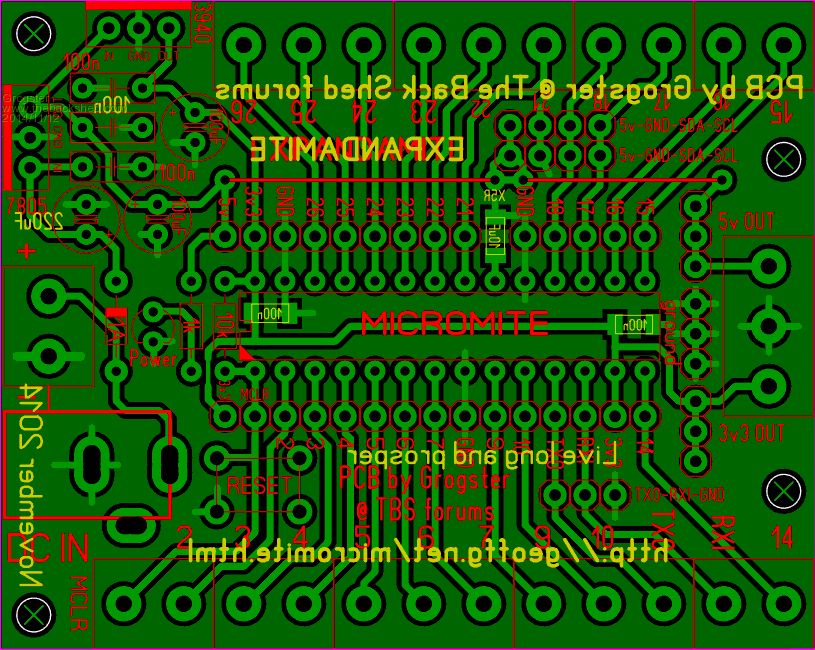
Added 2x 4-way headers for I2C - should be pin-compatible with those 8563 RTC modules that Mick linked me to. All things being equal, you can just plug it directly into the board, and you are ready to rock 'n' roll. That module is kinda long and skinny though, so it would probably be a better idea to solder it in for mechanical stability. Also added a 3-way header for the console. Whaddya think, guys - done board? EDIT: Some mock photoviews of the PCB. Top:(silkscreen) 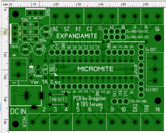
Bottom:(copper layer) 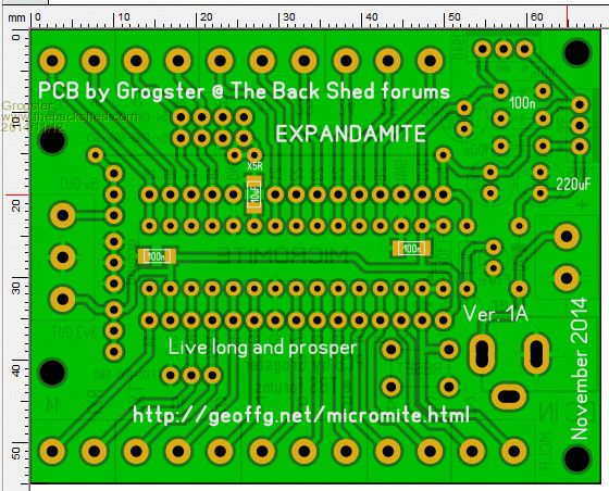
Smoke makes things work. When the smoke gets out, it stops! |
||||
| bigmik Guru Joined: 20/06/2011 Location: AustraliaPosts: 2981 |
That is looking really good Grogster, The 5v on the I2C is a good addition as well. Regards, Mick Mick's uMite Stuff can be found >>> HERE (Kindly hosted by Dontronics) <<< |
||||
| MicroBlocks Guru Joined: 12/05/2012 Location: ThailandPosts: 2209 |
Yeah. I like it!! Just a consideration for you to make about the parts used. You have the 100n capacitors in through hole and smd versions. Would it not be better to make all of them smd. It will make the BOM smaller and fewer types of parts are needed. Making it easier for someone to source the parts and a little cheaper as more of a single part can be used. I would change the silkscreen for the t-blocks slightly. On the bottom (pins 1-14) I would use four 3-way blocks and on the top five 2-way blocks. Is the 1k resistor on the mclr enough to the left to allow a dip socket? The power LED is now on the 5v. This will indicate that 5v is available but not if 3.3v is available. You could add another led, or change the connection of the led to the 3.3v. This would then indicate that 5v and 3.3v is available. And just for kicks. :) Add another pin for 3.3v to the console connector and make sure the order of the pins is right so that Geoffs vt100 terminal ( http://geoffg.net/terminal.html ) can be connected and powered directly from your board. :) Already getting tired from me? :) Microblocks. Build with logic. |
||||
| JohnS Guru Joined: 18/11/2011 Location: United KingdomPosts: 4330 |
I'm not really qualified to comment (can't design hardware) but it looks good. I've used 3V3 I2C so wonder a bit about the 5V for it. John |
||||
| MicroBlocks Guru Joined: 12/05/2012 Location: ThailandPosts: 2209 |
Very unfortunate that we live in a time were 5v, 3.3v and even other voltages are used. Now in hardware a 1 is not always a 1.:) Most hardware I used with i2c does indeed use 3.3v. Another pin and a wire link to have both available? There is still room available for it. Microblocks. Build with logic. |
||||
| atmega8 Guru Joined: 19/11/2013 Location: GermanyPosts: 738 |
Hi Grogster, i own a Sprint Layout License for the 6.0 Version. Would you please provide me with the raw board Format. So i can change what i want, to meet my requirements.. THX |
||||
| The Back Shed's forum code is written, and hosted, in Australia. | © JAQ Software 2026 |
